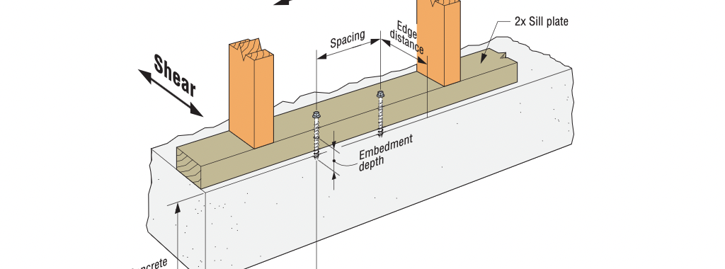
In the last few years, Simpson Strong-Tie has heard from a number of structural engineers expressing frustration with the lack of performance data for shallowly embedded, post-installed anchors (shallow anchors). Engineers of Record (EOR) have identified a common application for shallow anchors as those related to attachment of sill plates for structural and nonstructural wall-to-podium slab connections. One dilemma faced by the EORs originates in their desire to prevent damage to concrete podium slab reinforcement, especially where reinforcement is located close to the slab’s top surface to resist negative bending moments. EORs further indicate that shallow anchors are frequently needed for the following attachments: hanging MEP fixtures; attaching nonstructural components associated with tenant improvements; and anchoring light equipment.
Tag: Simpson Strong-Tie® Titen HD
Concrete Anchor Design for the International Building Code: Part 3
Specification of Concrete Anchors
The 2012 IBC and its Referenced Standard, ACI 318-11, is the first to mandate that contract documents specifically address installation, inspections and design parameters of concrete anchorage. For this reason, the specification of anchors in drawing details alone is impractical. To fully and effectively address these code mandates, concrete anchorage is more practically specified in both drawing detail(s) and the General
Structural Notes or specifications of the contract documents. The drawing detail(s) would typically call out the anchor type, material specification, diameter, and embedment depth. The General Structural Notes or specifications would include the name of the qualified anchor(s) and address the installation, inspections and design parameter requirements of ACI 318-11.
The following sections of ACI 318-11 discuss the contract document requirements for concrete anchorage:
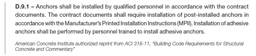
The commentary in ACI 318-11, RD.9.1 discusses the sensitivity of anchor performance to proper installation. It emphasizes the importance of qualified installers for all anchors, and compliance with the Manufacturer’s Printed Installation Instructions (MPII) for post-installed anchors. Training is required for adhesive anchor installers per ACI 318-11 D.9.1. Simpson Strong-Tie Co. Inc. provides free installer training by experienced Technical Sales Representatives for our adhesive, mechanical and specialty anchors. Contact us at 1-800-999-5099. Special inspection and proof loading are addressed in ACI 318-11 D.9.2
and D.9.2.1.
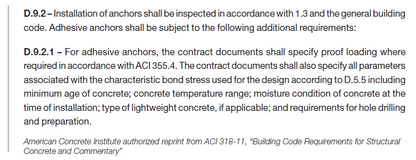
Per the section above, anchor installation requires inspection per Section D.9.2. In addition, the design parameters for adhesive anchors are required to be specified in the contract documents. An explanation of the design parameters listed in ACI 318-11 D.9.2.1 is provided below:
- Proof loading where required in accordance with ACI 355.4. Proof loading is only required for adhesive anchors loaded in tension in which the inspection level chosen for the adhesive anchor design is “Continuous” (Ref. ACI 355.4 Section 10.4.6). Selecting “Continuous Inspection” can result in a higher “Anchor Category,” which in turn results in a higher strength reduction factor, φ. Reference Section 13.3.4 of ACI 355.4 for the minimum requirements of the proof loading program, where required. The Design Professional is responsible for performing the quantity, the duration of
the applied load, and the proof load to which the anchors will be tested. These parameters will be specific to the anchor design conditions. - Minimum age of concrete at time of anchor installation. Per ACI 318 D.2.2, adhesive anchors must be installed in concrete having a minimum age of 21 days at time of anchor installation. Simpson Strong-Tie® has performed in-house testing of SET-XP®, AT-XP®, and ET-HP® adhesive anchors installed in 7-day- and 14-day-old concrete. The results of testing are published in an engineering letter (L-A-ADHGRNCON15.pdf), which can be viewed and downloaded at www.strongtie.com.
- Concrete temperature range. This is the in-service temperature of the concrete into which the adhesive anchor is installed. Temperature Ranges are categorized as 1, 2 or 3. Some manufacturers use A, B, or C as the category designations. Each Temperature Range category has a maximum short-term concrete temperature and a maximum long-term concrete temperature. Short-term concrete temperatures are those that occur over short intervals (diurnal cycling). Long-term concrete temperatures are constant temperatures over a significant time period.
- Moisture condition of concrete at time of installation. Moisture conditions, as designated by ACI 355.4, are “dry,” or “water-saturated.” Moisture condition impacts the characteristic bond stress of an adhesive.
- Type of lightweight concrete, if applicable.
- Requirements for hole drilling and preparation. These requirements are specific to the adhesive, and are described in the Manufacturer’s Printed Installation Instructions (MPII). Reference to the MPII in the contract documents is sufficient.
Adhesive anchors installed in a horizontal or upwardly inclined orientation that resist sustained tension loads require a “certified” installer.
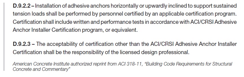
A certification program has been established by ACI/CRSI. Installers can obtain certification by successful completion of this program. Contact your local ACI or CRSI chapter for more information. Other means of certification are permitted, and are the responsibility of the licensed design professional.
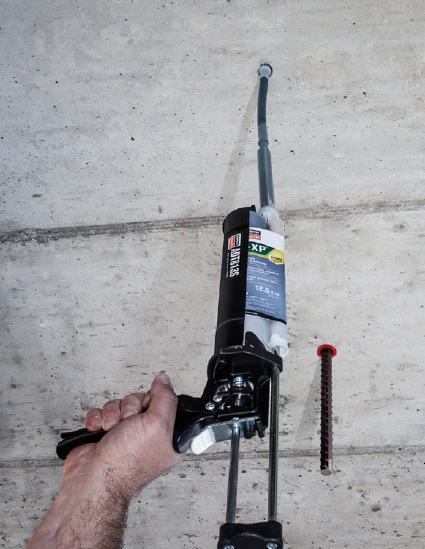
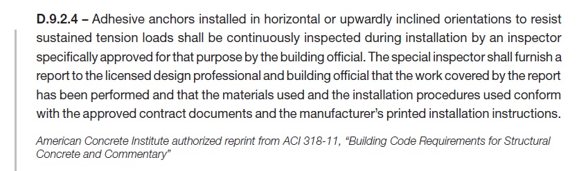
The installation of adhesive anchors in a horizontal or upwardly inclined orientation presents unique challenges to the installer. Simply put, the effects of gravity for these applications make it difficult to prevent air bubbles and voids, which can limit full adhesive coverage of the insert (threaded rod or reinforcing bar). Due to the increased installation difficulty of these anchors, they are required to be continuously inspected by a certified special inspector.
Suggested General Structural Notes or specifications for post-installed anchors can be viewed and downloaded at here, or contact a Simpson Strong-Tie® representative for help with your post-installed General Structural Notes or specifications.
Simpson Strong-Tie Suggested General Note for Anchor Products
Post-Installed Anchors into Concrete, Masonry and
Steel and Cast-in-Place Anchors into Concrete
The below products are the design basis for this project. Substitution requests for products other than those listed below may be submitted by the contractor to the Engineer-of-Record (EOR) for review. Substitutions will only be considered for products having a code Report recognizing the product for the appropriate application and project building code. Substitution requests shall include calculations that demonstrate the substituted product is capable of achieving the equivalent performance values of the
design basis product. Contractor shall contact manufacturer’s representative (800-999-5099) for product installation training and a letter shall be submitted to the EOR indicating training has taken place. Refer to the building code and/or evaluation report for special inspections and proof load requirements.
- For anchoring into cracked and uncracked concrete
a) Mechanical anchors shall have been tested in accordance with ACI 355.2 and/or ICC-ES AC193 for cracked concrete and seismic applications. Pre-approved products include:
i. Simpson Strong-Tie® Strong-Bolt® 2 (ICC-ES ESR-3037)
ii. Simpson Strong-Tie® Titen HD® (ICC-ES ESR-2713)
iii. Simpson Strong-Tie® Torq-Cut® (ICC-ES ESR-2705)
iv. Simpson Strong-Tie® Titen HD® Rod Hanger (ICC-ES ESR-2713)
v. Simpson Strong-Tie® Blue Banger Hanger® (ICC-ES ESR-3707, except roof deck insert)
b) Adhesive anchors shall have been tested in accordance with ACI 355.4 and/or ICC-ES
AC308 for cracked concrete and seismic applications. Adhesive anchors shall be installed
by a certified adhesive anchor installer where designated on the contract documents.
Pre-approved products include:
i. Simpson Strong-Tie® AT-XP® (IAPMO-UES ER-263)
ii. Simpson Strong-Tie® SET-XP® (ICC-ES ESR-2508)
III. Simpson Strong-Tie® ET-HP® (ICC-ES ESR-3372)
Concrete Anchor Design for the International Building Code: Part 2
Designing “Alternative Materials”
Concrete anchor types whose designs are not addressed in the IBC or its Referenced Standards, or are specifically excluded from the scope of the Referenced Standard (ACI 318-11), may be recognized as Alternative Materials. Section 1909 of the 2012 IBC requires that “The strength design of anchors that are not within the scope of Appendix D of ACI 318, shall be in accordance with an approved procedure.” Section D.2.2 of ACI 318-11 lists some concrete anchor types that are considered “Alternative Materials” and specifically excludes these anchors from its scope. The list of “Alternative Material” anchors provided in this section is not, however, a comprehensive list.
Section 104.11 of the 2012 IBC describes how the design professional must approach the design of Alternative Materials.
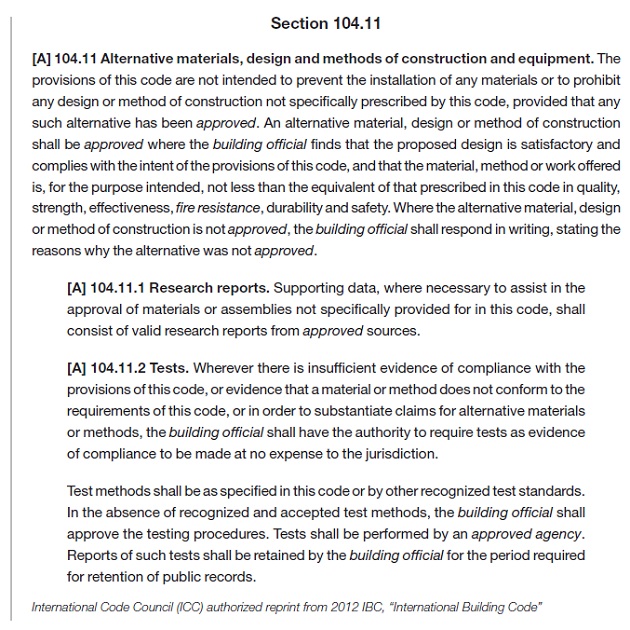
Section 104.11 provides the design professional with two options for the substantiation of the acceptable performance of an Alternative Material:
a. Research Reports. As described in the previous section (Design of Code Anchors), Research Reports are referenced as the primary source for the design and qualification of Alternative Materials. Research Reports for anchors are published by IAPMO UES or ICC-ES, both ANSI ISO 17065 accredited agencies. Publicly developed, majority-approved acceptance criteria are used to establish the test program and minimum performance requirements for an anchor type. Some Alternative Material anchor types have established acceptance criteria to which a product can be evaluated:
- Screw Anchors in Concrete (such as Simpson Strong-Tie® Titen HD®): ICC-ES AC193
- Headed Cast-in Specialty Inserts (such as Simpson Strong-Tie® Blue Banger Hanger®): ICC-ES AC446
- Powder- or Gas-Actuated Fasteners (such as Simpson Strong-Tie® PDPA and GDP): ICC-ES AC70
If Research Reports are used to substantiate an anchor’s performance, the design professional is bound by the design methodology and product limitations described in the Research Report.
b. Tests. If a Research Report is not available, and no acceptance criteria exists for a given anchor type, IBC Section 104.11 permits the use of tests performed in accordance with “recognized and accepted test methods” by an “approved agency” to substantiate performance. One example of an anchor type for which no acceptance criteria exists is:
- Helical Wall Ties (such as Simpson Strong-Tie® Heli-Tie™)
Cracked Concrete Determination
One of the many design considerations that the design professional must determine when designing either “Code Anchors” or anchors qualified as “Alternative Materials” is whether to consider the state of the concrete “cracked” or “uncracked.” The concrete state can significantly influence the anchor’s capacity. Neither the IBC nor ACI 318, Appendix D explicitly defines which applications should be categorized as “cracked” or “uncracked” concrete. The design professional must determine by analysis whether cracking will occur in the region of the concrete member where the anchors are installed. Absent an analysis to determine whether cracking will occur, the design professional may conservatively assume that the concrete state is “cracked.” With that said, there are two circumstances that require the design professional to design for “cracked” concrete:
a) Anchors in structures assigned to Seismic Design Categories C, D, E, or F (per 2012 IBC, Chapter 16) are required to be designed for “cracked” concrete unless the design professional can demonstrate that cracking does not occur at the anchor locations. The prequalification requirements of ACI 355.2 for mechanical anchors and ACI 355.4 for adhesive anchors include a test program that evaluates the performance of anchors in cracked concrete. Only anchors that have been tested and have passed the cracked concrete test program qualify for use in “cracked” concrete. The Research Report for a post-installed anchor (mechanical or adhesive) will clearly indicate whether it qualifies for use in “cracked concrete.”
b) Anchors located in a region of the concrete element where analysis indicates cracking at service level loading must be designed for “cracked” concrete (e.g. fr ≥ 7.5λ√f’c, ACI 318-11 eq. 9-10).
The design professional must consider additional factors that have the potential to result in concrete cracking in the region of anchorage. These factors include restrained shrinkage, temperature changes, soil pressure, and differential settlement. If no cracking is assumed in the region of the anchorage, the design professional should be able to justify that assumption.
Design Calculations
The design methodology in ACI 318 Appendix D is cumbersome. Calculations can be performed by hand using the design equations in Appendix D, inserting the substantiated data from an anchor manufacturer’s data tables or Research Reports to design with post-installed anchors. Designing with cast-in-place “Code Anchors” does not require additional data beyond what is included in ACI 318, Appendix D since these are “standard” anchors with standard design characteristics.
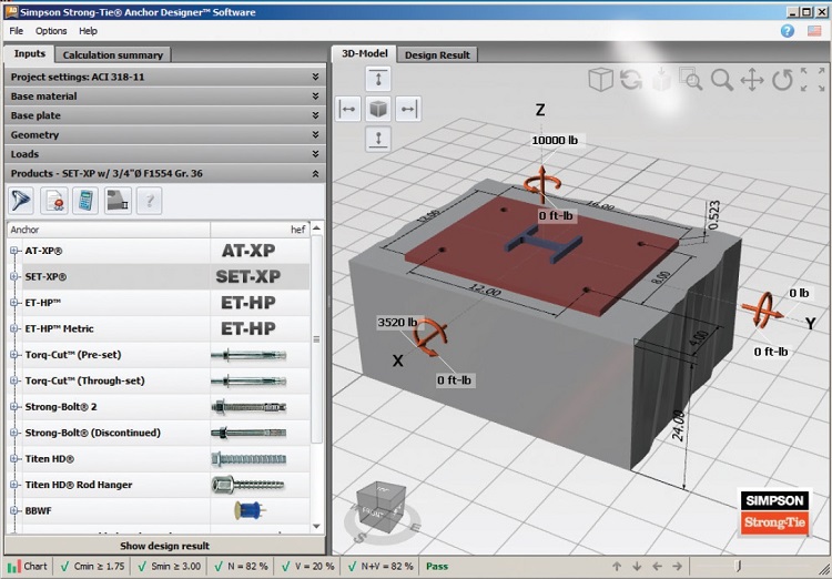
Performing hand calculations can be time-consuming, and for most design professionals is impractical due to the complexity of the design equations associated with multiple failure modes required to be considered. Design software, such as Simpson Strong-Tie® Anchor Designer™ Software for ACI 318, ETAG and CSA provides a fast, reliable method of calculating anchor performance for both cast-in-place and post-installed anchors. This software designs both “Code Anchors” and “Alternative Materials” for which an acceptance criteria exists.
Simpson Strong-Tie® Anchor Designer™ Software for ACI 318, ETAG and CSA is free and can be downloaded here.