Designing “Alternative Materials”
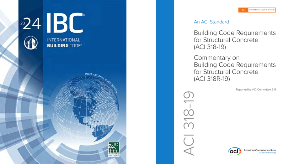
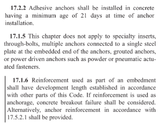
Concrete anchor types whose designs are not addressed in the IBC or its referenced standards, or are specifically excluded from the scope of the referenced standard (ACI 318-19 Chapter 17), may be recognized as Alternative Materials. Section 1901.3 of the 2024 IBC requires anchoring to concrete to be designed in accordance with ACI 318-19 Chapter 17, as supplemented by Section 1905, for anchor types that fall within its scope.
Anchor types that are excluded from the scope of ACI 318-19 Chapter 17 are therefore not considered code-prescribed anchors and must be evaluated as alternative materials, designs, or methods of construction. While ACI 318-19 Chapter 17 identifies certain anchor types that are excluded from its scope, the list of excluded anchor types is not intended to be comprehensive.
Section 104.2.3 of the 2024 IBC describes how the design professional must approach the design and approval of Alternative Materials, including demonstrating that the proposed system is equivalent to that prescribed by the code in terms of quality, strength, effectiveness, durability, and safety, subject to approval by the building official.
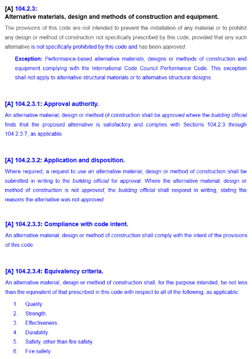
Section 104.2.3 of the 2024 IBC provides the design professional with two options for the substantiation of the acceptable performance of an Alternative Material:
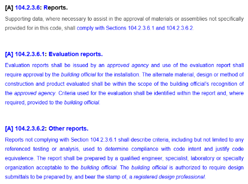
a. Evaluation Reports. As described in the previous section (Design of Code Anchors), Evaluation Reports are referenced as the primary source for the design and qualification of Alternative Materials. In accordance with IBC Section 104.2.3.6, supporting data submitted to assist in the approval of materials or assemblies not specifically provided for in the code shall comply with Sections 104.2.3.6.1 and 104.2.3.6.2. Evaluation reports, as addressed in Section 104.2.3.6.1, are issued by an approved agency and require approval by the building official for the installation. Evaluation Reports for anchors are published by IAPMO UES or ICC-ES, both ANSI ISO 17065 accredited agencies. Publicly developed, majority-approved acceptance criteria are used to establish the test program and minimum performance requirements for an anchor type. Some anchor types historically evaluated as Alternative Materials have established acceptance criteria. However, under the 2024 IBC, screw anchors in concrete are recognized as code anchors when designed in accordance with ACI 318-19 Chapter 17 and therefore are no longer considered Alternative Materials. Examples of anchor types for which acceptance criteria have been developed include:
- Headed Cast-in Specialty Inserts: ICC-ES AC446
- Powder- or Gas-Actuated Fasteners (such as Simpson Strong-Tie® PDPA and GDP): ICC-ES AC70
If Evaluation Reports are used to substantiate an anchor’s performance, the design professional is bound by the design methodology and product limitations described in the Evaluation Report.
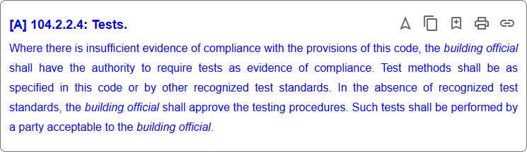
b. Tests
If an evaluation report is not available and no acceptance criteria exist for a given anchor type, IBC Section 104.2.2.4 permits the use of tests to demonstrate compliance where there is insufficient evidence of code conformity. Tests must be performed using recognized test standards, or other testing procedures approved by the building official, and conducted by a party acceptable to the building official. One example of an anchor type for which no published acceptance criteria currently exist is:
- Helical Wall Ties (such as Simpson Strong-Tie® Heli-Tie™)
Cracked Concrete Determination
One of the many design considerations that the design professional must determine when designing either “Code Anchors” or anchors qualified as “Alternative Materials” is whether to consider the state of the concrete “cracked” or “uncracked.” The concrete state can significantly influence the anchor’s capacity. Neither the 2024 IBC nor ACI 318-19 Chapter 17 explicitly defines which applications should be categorized as “cracked” or “uncracked” concrete. The design professional must determine by analysis whether cracking will occur in the region of the concrete member where the anchors are installed. Absent an analysis to determine whether cracking will occur, the design professional may conservatively assume that the concrete state is “cracked.” With that said, there are two circumstances that require the design professional to design for “cracked” concrete:
a) Anchors in structures assigned to Seismic Design Categories C, D, E, or F (per 2024 IBC Chapter 16, referencing ASCE/SEI 7) are required to be designed for “cracked” concrete unless the design professional can demonstrate that cracking does not occur at the anchor locations. The prequalification requirements of ACI 355.2 for mechanical anchors and ACI 355.4 for adhesive anchors include a test program that evaluates the performance of anchors in cracked concrete. Only anchors that have been tested and have passed the cracked concrete test program qualify for use in “cracked” concrete. The Evaluation or Research Report for a post-installed anchor (mechanical or adhesive) will clearly indicate whether it qualifies for use in “cracked concrete.”
b) Anchors located in a region of the concrete element where analysis indicates cracking at service level loading must be designed for “cracked” concrete (ACI 318-19 Eq. (19.2.3.1)).
![]()
The design professional must consider additional factors that have the potential to result in concrete cracking in the region of anchorage. These factors include restrained shrinkage, temperature changes, soil pressure, and differential settlement. If no cracking is assumed in the region of the anchorage, the design professional should be able to justify that assumption.
Design Calculations
The design methodology in ACI 318-19 Chapter 17 is detailed and can be cumbersome. Calculations can be performed by hand using the design equations in Chapter 17, inserting the substantiated data from an anchor manufacturer’s data tables or applicable evaluation or research reports to design with post-installed anchors. Designing with cast-in-place “Code Anchors” does not require additional data beyond what is included in ACI 318-19 Chapter 17 since these are “standard” anchors with standard design characteristics.
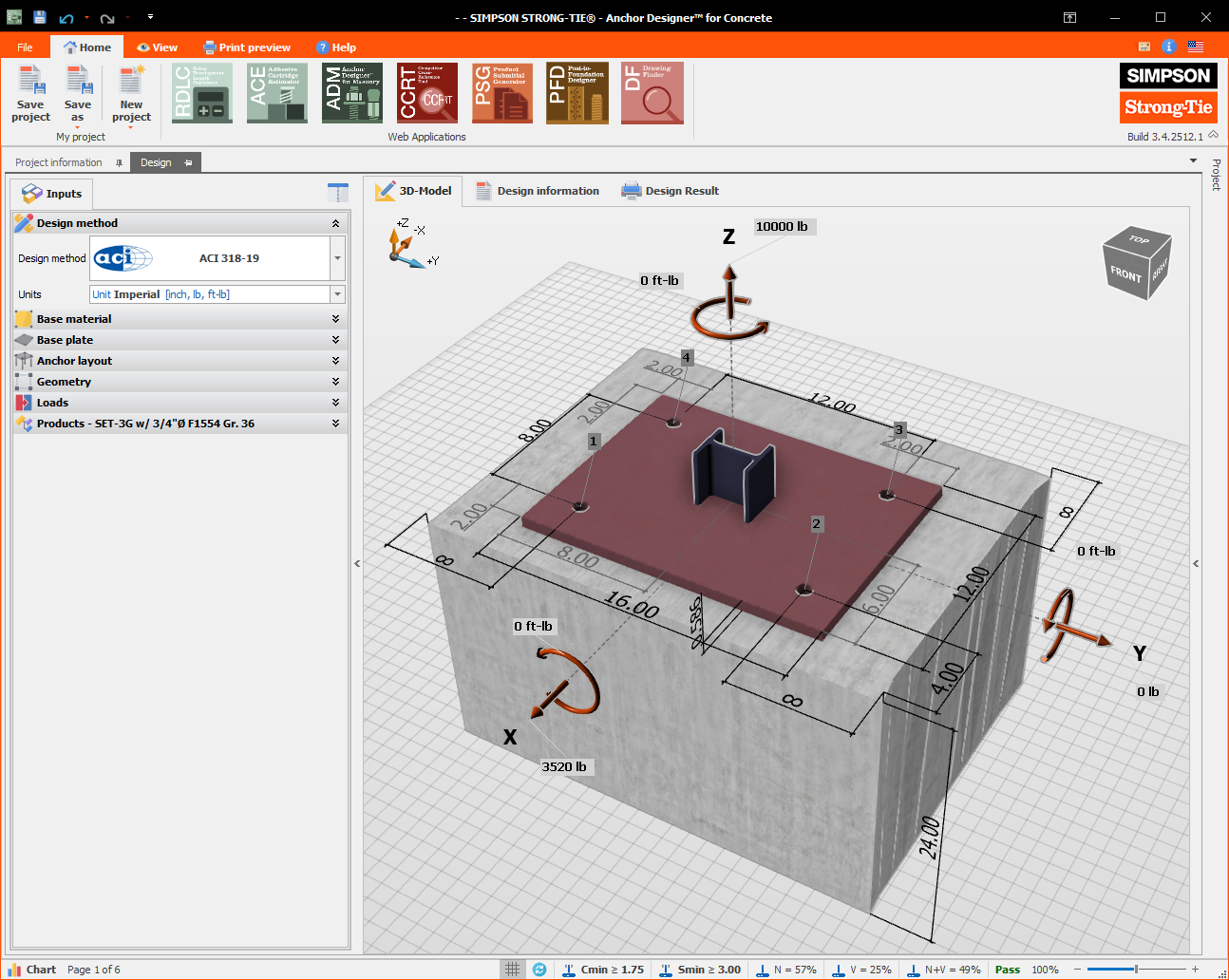
Performing hand calculations can be time-consuming, and for most design professionals is impractical due to the complexity of the design equations associated with multiple failure modes required to be considered. Design software, such as Simpson Strong-Tie® Anchor Designer™ Software for ACI 318, ETAG and CSA provides a fast, reliable method of calculating anchor performance for both cast-in-place and post-installed anchors. This software designs both “Code Anchors” and “Alternative Materials” for which an acceptance criteria exists.
Simpson Strong-Tie® Anchor Designer™ Software for ACI 318, ETAG and CSA is free and can be downloaded here.