Can Decorative Hardware Add Structural Strength?

At Simpson Strong-Tie, we really try to listen to our customers. Our products are developed with your needs in mind.

Last year, at my daughter’s college orientation, I found myself in an interesting conversation with one of the other parents. It turned out that he owns a deck-building company. When he found out that I’m an engineer at Simpson Strong-Tie, his first question was “why don’t you guys make some nice-looking connections that I can use on my decks?”
Ugly Connector
Ugly Connector

I had to choke back a laugh because that’s exactly what I was working on at the time. What he didn’t mention (but we knew he also needed) were connectors that are fast to install, suitable for outdoor use and structurally rated for engineered designs. We also knew code approval was critical to help building departments approve the designs.

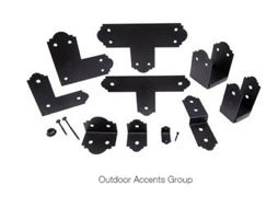
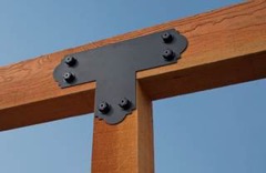
The Outdoor Accents® connectors we designed include some basic T’s, L’s, angles and post bases with a nice architectural feature of decorative edges from our Mission Collection®. The steel has our ZMAX® (G185) galvanizing (which is twice as heavy as our standard G90) to resist corrosion and a black powder-coat finish for aesthetics.

outdoor-accents-group outdoor-accents-strap

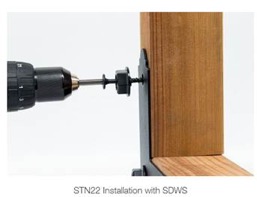
But the real innovation is in the fastener. Architectural connectors and big bolts go hand in hand, but big bolts are expensive, time consuming and often structurally unnecessary. To solve the installation issue, we designed a decorative washer that looks like a washer and nut and perfectly fits our SDWS22DBB Structural Wood screw.

stn22-installation-with-sdws

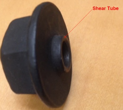
We named it the shear tube nut (STN) because the extended tube increases the shear area in contact with the connector.

shear-tube

Together with the SDWS22DBB screw, this solution looks like a bolted connection but installs with the speed and ease of a self-tapping screw. Structurally as well, the hardware is comparable to a bolted connection with a shear capacity of 470 lb. per fastener when used with metal side plates, i.e., connectors.1  The solution has also been tested and load rated for use directly on wood, so it can be used for a variety of other connections such as joining multi-ply beams, knee braces, etc.

In order to be code approved, the SDWS22DBB screws were tested with and without the STN in both wood-to-wood and metal-to-wood per AC233 Acceptance Criteria for Alternate Dowel-Type Threaded Fasteners. The connectors and fasteners, including STN, were tested as assemblies per ASTM D7147. Code agency reviewers quickly saw the benefits of the design and issued evaluation reports verifying the loads. The Outdoor Accents® connectors and SDWS22DBB screws are recognized under IAPMO UES ER-280 and ER-192, respectively. The smaller APA21 angle uses our new SD10112DBB screw, which is listed in ICC-ES ESR-3046.

My deck-builder friend will be pleased to see the new connectors are now available at select Home Depot stores.

outdoor-accents-project

I can’t wait to see what he thinks of them and to get his ideas for the next big project. How about you?  What would you build with these new architectural products?  Let us know in the comments below.

  1. Ref. IAPMO UES ER-192 Table 6A steel side member DF = 470 lb.; 2015 NDS Table 12B 3 1/2″ main member, 1/2″ bolt, DF perpendicular-to-grain = 510.

Outdoor Accents®

Add Beauty and Strength to Your Custom Outdoor Living Structures.


Deck Guardrail Update

This post is an update to David Finkenbinder’s post on Guard Post Resources from August 13.

As David explained, the requirements in the IRC and IBC for guards are intended to prevent people from falling off of raised surfaces. The failure of this guard is a common source of injuries caused by failures of deck components.

Section R312.1.1 of the 2012 International Residential Code (IRC) states that “Guards shall be located along open-sided walking surfaces, including stairs, ramps and landings, that are located more than 30 inches measured vertically to the floor or grade below at any point within 36 inches horizontally to the edge of the open side.”

Table 301.5 of the 2012 IRC requires that guards and handrails be designed for “[a] single concentrated load” of 200 pounds “applied in any direction at any point along the top.”

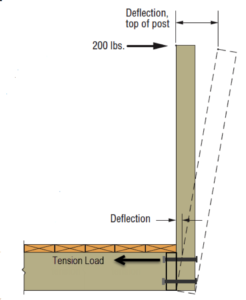
David mentioned the article Tested Guardrail Post Connections for Residential Decks, which described a testing program at Virginia Tech that examined the ability of various assemblies to resist this concentrated load at the top of the guard post. But rather than test in any direction, the researchers decided to test in what they considered the most critical direction: outward away from the deck.

Deck guardrail deflection

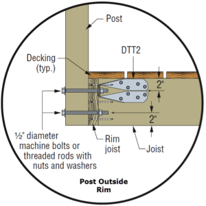
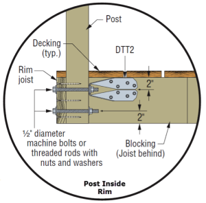
Simpson Strong-Tie subsequently developed a new tension tie, the DTT2Z, to make an economical connection from the top bolt in a deck post back into the framing of the deck to resist the high tension forces that develop in the top bolt when the top of the post is pushed outward. Several details were developed to try to address the various orientations of the post and deck framing.

SE Blog 2 

To allow evaluation of assemblies used to resist this deck guardrail force, ICC-ES developed AC273, Acceptance Criteria for Handrails and Guards. AC273 is available for purchase through the ICC bookstore.

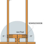
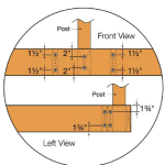
Even with the connectors being readily available, deck builders have asked for guard post connection details that do not involve the use of connection hardware. So Simpson Strong-Tie again tested several framing configurations according to the AC273 criteria, using our Strong-Drive® SDWS TIMBER screws and additional blocking to try to prevent the post from rotating. These details are shown in the engineering letter L-F-SDWSGRD15.

SE Blog 4SE Blog 5SE Blog 6

That brings us to the update part.

A committee made up of building officials, manufacturers, deck builders, designers and other interested parties is currently developing a set of code proposals on deck construction for inclusion in the 2018 International Residential Code (IRC). Even though more and more deck information has been incorporated into the last few editions of the IRC, there is still insufficient information in the code to be able to completely build a deck prescriptively. One area of interest is this guard connection. There is a desire to develop prescriptive details for both connection of a 4×4 post to deck framing with blocking and fasteners and for connecting the deck band joist back to the deck framing so that pre-manufactured guard rails can simply be fastened to the deck band with the knowledge that the connection is secure.

The problem is that, with the current requirement, the guard must resist the 200-pound load in ANY direction. All current testing, including AC273, only uses testing in the outward direction away from the floor of the deck. If the post were really required to resist a 200 pound load in the inward direction as well, then two hardware connectors would be required, one on each bolt. However, the belief of the committee is that resistance of 200 pounds in the outward and downward direction is primarily what is needed to ensure the safety of the occupants of the deck.

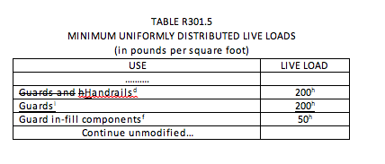
So they are working on a code proposal to change Table R301.5 of the IRC to require that the guard only resist the 200 pounds in the outward and downward direction and reduce the load to 50 pounds in the inward and upward direction.

The committee recognizes that while this is not necessarily a departure from current practice, it is a departure from current loading requirements in the IRC, IBC, and ASCE 7. So representatives of Simpson Strong-Tie met on September 30 with the NCSEA Code Advisory Committee – General Requirements Subcommittee to get the opinions of this group of active structural engineers. They provided valuable input, including the consideration that at some locations near landings and other changes in elevation, resistance to 200 pounds in the inward direction could be important.

Prior to incorporation of NCSEA’s input, the committee thought the code change might look as shown below.

We are interested in getting additional comments on this code proposal. What do you think? Let us know in the comments below.

Screen Shot 2015-10-15 at 5.23.23 PM


d) A single concentrated load applied in any direction at any point along the top, in pounds.

f) Guard in-fill components (all those except the handrail), balusters and panel fillers shall be designed to withstand a horizontally applied normal load of 50 pounds on an area equal to 1 square foot. This load need not be assumed to act concurrently with any other live load requirement.

h) Glazing used in handrail assemblies and guards shall be designed with a safety factor of 4. The safety factor shall be applied to each of the concentrated loads applied to the top of the rail, and to the load on the in-fill components. These loads shall be determined independent of one another, and loads are assumed not to occur with any other live load.

j) A single concentrated load applied at any point along the top, in pounds. The 200-pound load is required to be applied in either the outward or downward direction, and it is permitted to be reduced to 50 pounds in either the inward or upward direction. The guard is not required to resist these loads applied concurrently with each other.

Wood-framed Deck Guard Post Resources and Residential Details

A deck and porch study reported that 33% of deck failure-related injuries over the 5-year study period were attributed to guard or railing failures. While the importance of a deck guard is widely known, there was a significant omission from my May 2014 post on Wood-framed Deck Design Resources for Engineers regarding the design of deck guards.

A good starting point for information about wood-framed guard posts is a two-part article published in the October 2014 and January 2015 issues of Civil + Structural Engineer magazine. “Building Strong Guards, Part 1” provides an overview of typical wood-framed decks, the related code requirements and several examples that aim to demonstrate code-compliance through an analysis approach. The article discusses the difficulties in making an adequate connection at the bottom of a guard post, which involve countering the moment generated by the live load being applied at the top of the post. Other connections in a typical guard are not as difficult to design through analysis. This is due to common component geometries resulting in the rails and balusters/in-fill being simple-supported rather than cantilevered. “Building Strong Guards, Part 2” provides information on the testing approach to demonstrate code-compliance. Information about code requirements and testing criteria are included in the article as well.

Research and commentary from Virginia Tech on the performance of several tested guard post details for residential applications (36” guard height above decking) is featured in an article titled “Tested Guardrail Post Connections for Residential Decks” in the July 2007 issue of Structure magazine. Research showed that the common construction practice of attaching a 4×4 guard post to a 2x band joist with either ½” diameter lag screws or bolts, fell significantly below the 500 pound horizontal load target due to inadequate load transfer from the band joist into the surrounding deck floor framing. Ultimately, the research found that anchoring the post with a holdown installed horizontally provided enough leverage to meet the target load. The article also discussed the importance of testing to 500 pounds (which provides a safety factor of 2.5 over the 200-pound code live load), and the testing with a horizontal outward load to represent the worst-case safety scenario of a person falling away from the deck surface.

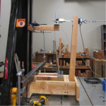
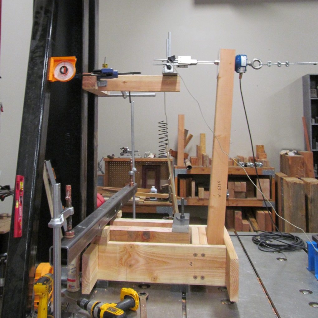
Simpson Strong-Tie has tested several connection options for a guard post at the typical 36” height, subjected to a horizontal outward load. Holdown solutions are included in our T-GRDRLPST10 technical bulletin. In response to recent industry interest, guard post details utilizing blocking and Strong-Drive® SDWS TIMBER screws have been developed (see picture below for a test view) and recently released in the engineering letter L-F-SDWSGRD15. The number of screws and the blocking shown are a reflection of the issue previously identified by the Virginia Tech researchers – an adequate load path must be provided to have sufficient support.

SDWS Detail C: Interior Post on Rim Joist between Joists, at 500-Pound Horizontal Test Target Load

Have you found any other resources that have been helpful in your guard post designs? Let us know by posting a comment.