


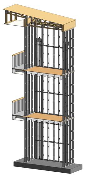
The number of midrise structures constructed using light-frame cold-formed steel (CFS) certainly seems to be increasing each year. As with any material, there are benefits and challenges, especially in areas of moderate to high seismic risk. This post will discuss these as well as potential solutions.
Light-frame CFS midrise construction often uses ledger floor framing primarily to facilitate the load transfer detailing at the floor, tension anchorage (tie-downs or hold-downs) and compression chord studs or posts designed to resist the amplified seismic overturning loads. CFS framing is typically thin and singly symmetric.

Amplified Seismic Load
The AISI Lateral Design standard (AISI S213-07/S1-09) Section C5.1.2 requires that the nominal strength of uplift (tension) anchorage and the compression chord studs for shear walls resist the lesser of (1) the amplified seismic load or (2) the maximum load the system can deliver when the response modification coefficient, R, greater than 3. The amplified seismic load is defined as the load determined using the ASCE 7 seismic load combinations with the overstrength factor, Wo, which may be taken as 2.5 for CFS framed shear wall systems with flexible diaphragms.
Typically, the maximum the system can deliver to the uplift anchorage or chord studs is taken as the forces determined using the nominal shear strength of the shear wall assembly tabulated in the seismic shear wall table in S213 multiplied by 1.3. The S213 commentary accounts for the tabulated loads being based on Sequential Phased Displacement (SPD) rather than CUREE cyclic protocol and the degraded backbone curve. See the Structure magazine article that discusses the design of CFS framed lateral force-resisting systems.
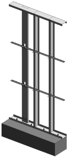
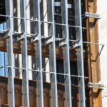
Continuous Rod Tie-Down Systems
Light-framed CFS over three stories often use continuous rod tie-down systems rather than cold-formed steel hold-downs to resist shear wall overturning forces as they offer increased load capacity. Neglecting the dead load contribution, the amplified seismic load requirement for CFS shear walls using an R greater than 3 results in an 80% increase in the load used to size the continuous rod tie-down system compared to design level loads. For shear walls using an R greater than 3, it is important to note on the design drawings whether the uplift loads shown are ASD, LRFD, amplified ASD or amplified LRFD so the appropriate tie-down system may be designed.
Continuous rod tie-down systems are designed not only for strength, but also checked to ensure they do not deflect too much to cause the top of shear wall drift to exceed the code limit or to exceed the 0.20” vertical story deflection limit required by some jurisdictions and ICC-ES AC316. Take-up devices are used in CFS framed structures to take-up construction and settlement gaps that may occur. AISI S200 Section C3.4.4 states that a gap of up to 1/8” might occur between the end of wall framing and the track. The vertical elongation of the continuous rod tie-down system includes rod elongation (PL/AE) and the take-up device deflection due to the seating increment and the deflection under load.
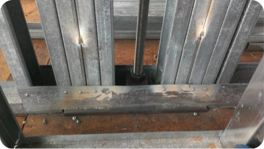
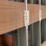
In addition, coordination is important in using continuous rod tie-down systems in CFS structures because the walls are often prefabricated offsite. An example is the consideration of the appropriate detail for the steel bearing plate installed at the floor sheathing in the story above to resist the uplift (tension) force from the story below.
One possible detail is to install the bearing plate in the bottom CFS track under all the CFS chord studs, but it’s important to ensure the bottom track flanges are deep enough to screw them to the stud flanges as the bearing plate can have a thickness of 1 ½” or more and typical tracks use 1 ¼” flanges. It is also important to ensure that the bearing plate width fits in the track. Another possible detail is to install the bearing plate under the CFS track under all the CFS chord studs. However, then it must be cut into the floor sheathing and may cause the bottom track to be raised at the bearing plate. For this detail, the floor shear transfer must be detailed through the ledger into the CFS framing.
Concrete Tension Anchorage
The concrete tension anchorage is designed according to ACI 318 Appendix D using the continuous steel rod material and size in accordance with S213 to have the nominal strength to resist the lesser of the amplified seismic force or the maximum load the system can deliver. ACI 318-11 Section D.3.3.4.3 offers four force limits for design of concrete tension anchorage design in Seismic Design Category C through F:
(1) The concrete nominal tension anchorage strength shall be greater than 1.2 times the ductile steel rod nominal tension anchorage strength
(2) The anchorage design strength shall be greater than the maximum tension force that can be delivered by a yielding attachment;
(3) The anchorage design strength shall be greater than the maximum tension force that can be delivered by a non-yielding attachment; and
(4) The anchorage design strength shall be greater than the amplified seismic force.
Typically either option (1) or (4) is used where (1) would lead to less concrete required than (4) if the bolt is efficiently sized while (4) would be required for such conditions as a vertical irregularity. See the concrete anchorage and podium anchorage SE Blog posts for more details.

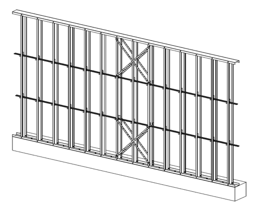
CFS Wall Stud Bracing
CFS studs are typically thin and singly symmetric and thus require bracing. AISI S211 (Wall Stud Design Standard) permits two types of bracing design that cannot be combined; sheathing based or steel based. There are limits on the stud axial strength when using sheathing braced design. It’s important to identify on the drawings that the sheathing braces the studs and another load combination must be used for the stud design.
2012 IBC Section 2211.4 requires stud bracing to be designed using either AISI S100 (North American Specification) or S211 (Wall Stud Design Standard). S100-07 Section D3.3 required nominal brace strength is to be 1% of the stud’s nominal compressive axial strength, but S100-12 Section D3.3 changes this to the required brace strength is to be 1% of the stud’s required compressive axial strength (demand load). In addition, D3.3 requires a certain stiffness for each brace. AISI S211 required brace strength is to be 2% of each stud’s required compressive axial strength for axially loaded studs and, for combined bending and axial loads, be designed for the combined brace force per S100 Section D3.2.2 and 2% of the stud’s required compressive axial strength.
There are two primary types of steel stud bracing systems: bridging and strap bracing. U-channel bridging extends through the stud punchouts and is attached to the stud with a clip, of which there are various solutions such as this post on Wall Stud Bridging. Bridging bracing requires coordination with the building elements in the stud bay. It installs on one side of the wall, and does not bump out the wall sheathing. It also requires periodic anchorage to distribute the cumulative bracing loads to the structure for axially loaded studs often using strongback studs and does not require periodic anchorage for laterally loaded studs since the system is in equilibrium as the torsion in the stud is resisted by the U-channel bending.
Flat strap bracing is installed on either side of the wall and at locations other than the stud punchout. It bumps out the sheathing and requires periodic anchorage to distribute the cumulative bracing loads to the structure for axially and laterally loaded studs.
![]()

![]()
Light-frame cold-formed steel construction has been used successfully for many projects, but there are challenges that must be addressed to ensure code compliance and desired performance. Some beneficial resources for designing CFS structures are the SEAOC 2012 IBC Structural/Seismic Design Manual Volumes 1 and 2 and the Cold-Formed Steel Engineers Institute’s (CFSEI) website where you can find technical notes and design guides.
What have been some of your observations or challenges in designing cold-formed steel midrise structures?


How the seismic force is distributed to different wall panels using diagonal strap bracings? Can anyone give me procedure?