

This post is the second of a two-part series on the results of research on anchorage in reinforced brick. The research was done to shed light on what tensile values can be expected for adhesive anchors. In last week’s post, we covered the test set-up. This week, we’re taking a look at our results and findings.
To briefly recap the test set up, it was conducted in September 2014, at an office building in Burbank, Calif. Slated for demolition, this building provided an opportunity for Simpson Strong-Tie to install and test 1/2-inch diameter anchors using Simpson Strong-Tie® SET-XP® anchoring adhesive in both the face and end of the 8-1/2 inch wide reinforced brick wall. A 12-ton rated pull rig at the face and end of the wall was used to pull test the anchors to failure.
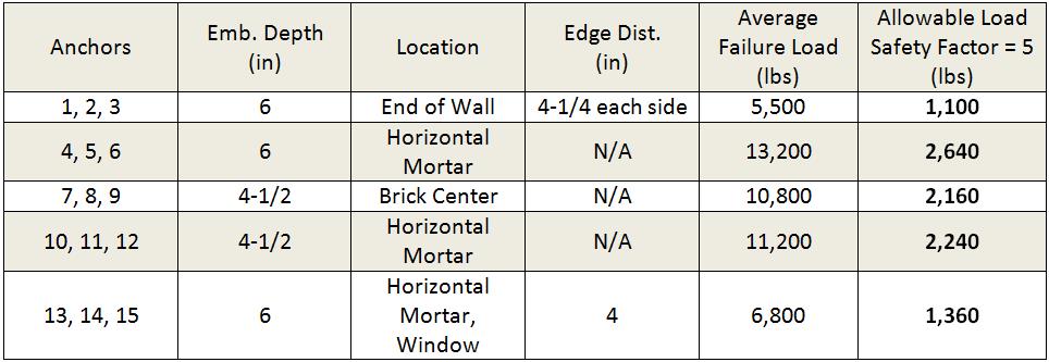
Table 1 shows the results for both face and end of wall anchors. Each data set was limited to testing three anchors of the same diameter and embedment depth. The coefficient of variation (COV) showed that the spread of the data was fairly narrow (11% maximum) for the face of wall anchors, but much higher for the end of wall anchors (24%). There are a couple of things worth noting here.
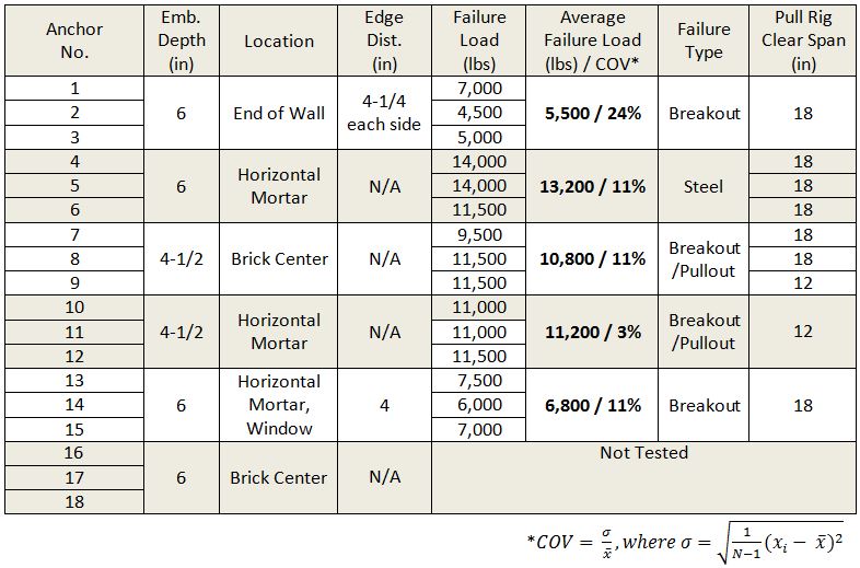
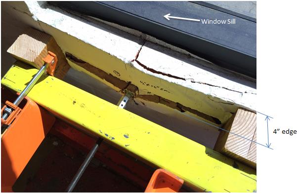
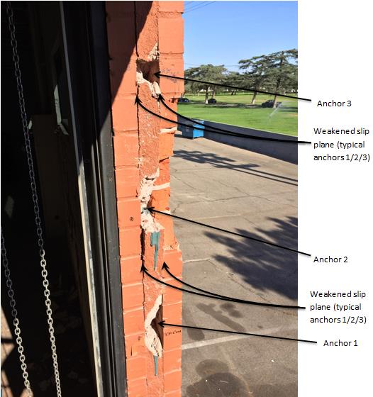
Anchors 4, 5 and 6 showed that reinforced brick is capable of achieving significant capacity for anchors embedded past the grouted portion of the wall to a depth of six inches. The threaded rods were a mix of F1554 Gr. 36 (newer specification) and A307 Gr. C (older specification – likely the anchors that failed at 14,000 lbs.), which might explain the observed variation in capacity for anchors 4, 5 and 6. At what point breakout would have been achieved if higher tensile strength steel had been used is unknown but it can be estimated. What is clear is a significant reduction – probably around 60% (relative to an estimated breakout capacity of around 17,000 lbs. for an anchor embedded six inches deep far away from an edge) – can be expected for near-edge conditions, despite the presence of two #4 bars running along the edge of the wall at the window. A near-edge failure is shown in Figure 6.
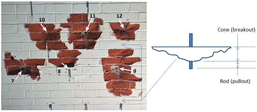
At a reduced embedment depth of 4-1/2 inches, Table 1 showed that anchor location (anchors 7 through 12) had little effect on performance whether anchors were installed in the middle of the brick or in the head joint mortar. The failure modes were largely a combination of breakout and pullout as shown in Figure 7 and 8.
The end of wall anchor results shown in Table 1 revealed a significant reduction in adhesive tensile capacity and greater variation (COV) relative to face of wall results. Two possible contributing factors for such a high COV could be:
1) The bond strength between the grout and surrounding brick wythes is variable, and
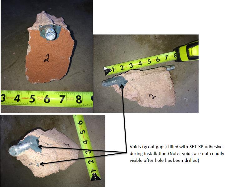
2) The size and quantity of the voids present in the grout is probably inconsistent along the height of the wall – some areas are better than others – leading to further variation of the test results.
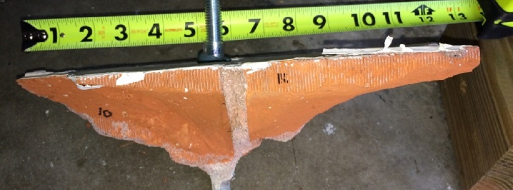
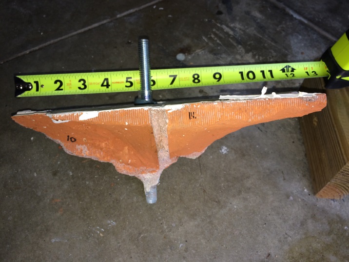
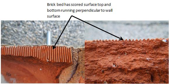
Figure 9 shows evidence of a slip plane failure for anchors 1, 2 and 3. Looking at the brick top and bottom surface, referred to as the bed, a scored surface can be seen running perpendicular to the length of the brick (and hence the wall surface) as shown in Figure 10. Perhaps the intent of scores is to help improve the bond strength between the brick and mortar. But this assumed benefit is limited to the bed line. The face and side of the brick are smooth. Consequently, the bond strength between the grout and brick is low enough, combined with lack of grout confinement between the two wythes, to have an appreciable effect on the anchor ultimate tensile capacity.
To summarize, this test program discovered that the tensile performance of 1/2-inch adhesive anchors in the face of the wall can be substantial for cases where anchors are located far enough away from a free edge. Performance is similar for anchors placed in the center of the brick or in the mortar joint, suggesting it doesn’t matter where the anchors are placed on the wall (obviously this isn’t true for anchors near a free edge). Special precautions should be taken especially for anchors located near an edge where small intermittent voids may exist in the grout. Anchor installation should ensure that sufficient quantity of adhesive has been injected into the hole. Figure 11 proves that this is possible. However, screen tubes should be considered if large voids are present, although large voids are expected to be rare in reinforced brick. End of wall anchorage applications should be designed carefully especially if significant tensile capacity is a design requirement.
Determining what the allowable load should be can be a little tricky. ICC-ES AC 58, the criteria used for adhesive anchors in masonry base material, lists several safety factors depending on whether creep and/or seismic tests have been performed. Conducting creep and seismic tests on an outdated building material like reinforced brick would be difficult because replicating 60- year-old construction accurately in the laboratory will probably be difficult. Reinforced brick has been largely replaced by grout-filled CMU as the preferred masonry building material — at least in Southern California. What safety factor should be used that would permit seismic loading of anchors in a relatively antiquated building material like reinforced brick is debatable. Perhaps AC 60, the criteria used for assessing adhesive anchor performance in unreinforced masonry elements (URM), would serve as the best guide. It requires a minimum safety factor of five against failure and limits adhesive anchors to resisting earthquake loads only. But AC 60 also requires that the average ultimate load used not exceed an axial displacement of 1/8″ and limits the allowable load to no more than 1,200 lbs.
Despite the obvious structural dissimilarity between URM and reinforced brick and additional AC 60 requirements, Table 2 shows what the allowable loads would look like for the results of this test program if a safety factor of five was chosen. These loads are based on a wall of unknown material properties (compressive strength, tensile strength and bond, etc.) for a specific building, and may not apply to other reinforced brick buildings.
Many factors were not investigated in this test program, such as shear, creep, the simulated seismic test, just to name a few. While the evidence so far suggests that an adhesive anchor in reinforced brick performs similarly to grout-filled CMU, more testing would be necessary to substantiate this claim fully. What is very clear is the tensile tests performed on the 60-year-old Burbank office building showed that reinforced brick is a material capable of resisting appreciable anchorage forces. Of course, while a major effort is made by manufacturers to provide engineers with lab tested “code values” for design use, it can’t be ignored that the material properties of any structural element can be variable. Additional factors such as material deterioration, workmanship, etc., can all have an effect on anchorage capacity. This means that it’s never a bad idea to assess anchor performance through site-specific pull tests if gauging strength accurately is important to the anchor system design.
What have your experiences been with reinforced brick? Have you called for pull tests in this material? What were the results? Please feel free to share your experiences in the comments below.

Related Posts
 Part I: Tensile Performance of Simpson Strong-Tie® SET-XP Adhesive in Reinforced Brick: Test Set Up
 Dry, Soaked, or Submerged Concrete — SET-3G Adhesive Allows Anchoring in Any Condition
 90 Years Later — How the Long Beach Earthquake Changed California’s Approach to School Construction
 Simpson Strong-Tie® SET-3G™ Adhesive Offers a Ductile Solution for Post-Installed Anchorage near a Concrete Edge