


This week’s blog post is written by Jason Oakley. Jason is a California registered professional engineer who graduated from UCSD in 1997 with a degree in Structural Engineering and earned his MBA from Cal State Fullerton in 2013. He is a field engineer for Simpson Strong-Tie who has specialized in anchor systems for more than 12 years. He also covers concrete repair and Fiber-Reinforced Polymer (FRP) systems. His territory includes Southern California, Hawaii and Guam.
This post is Part I of a two-part series. In this post, we’ll cover the test set-up and next week in Part II, we’ll take a look at our results and findings.
More than half a century ago, reinforced brick was a fairly common construction material used in buildings located in Southern California and probably elsewhere in the U.S. Reinforced brick can be found in schools, universities, and office buildings that still stand today. This material should not be confused with unreinforced brick masonry (URM) that is also composed of bricks but is structurally inferior to reinforced brick. Engineers are often called to look at existing reinforced brick structures to recommend retrofit schemes that, for example, might strengthen the out-of-plane wall anchorage between the roof (or floor) and wall to improve building performance during an earthquake. Yet, limited or no information exists on the performance of adhesive anchors in this base material. This series of posts shares the results of research on anchorage in reinforced brick in hopes of shedding light on what tensile values can be expected for adhesive anchors, including any important findings encountered during installation and testing.
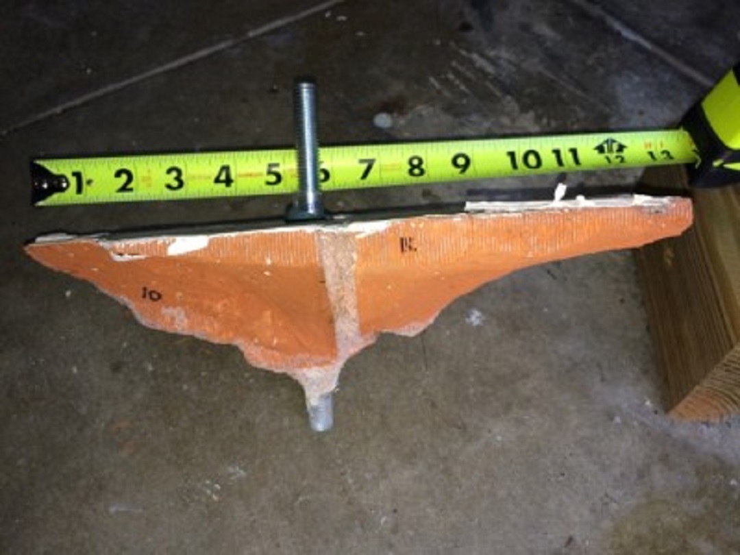
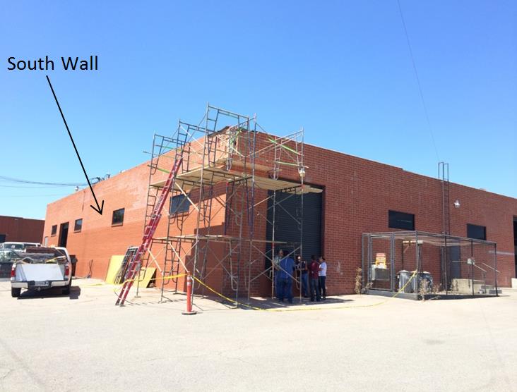
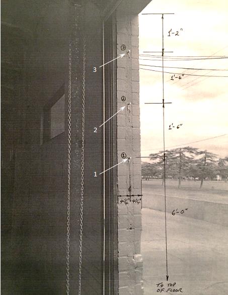
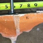
In September 2014, one wall of an office building in Burbank, CA, was slated for demolition. This presented an opportunity for Simpson Strong-Tie to install and test 1/2-inch diameter anchors using Simpson Strong-Tie® SET-XP® anchoring adhesive in both the face and end of the 8-1/2 inch wide reinforced brick wall. The building is shown in Figure 1 and the wall cross section is shown in Figure 2. The bricks measured 3 inches wide by 3-1/2 inches tall by 11-1/2 inches long and the drawings required that the bricks conform to ASTM C62-50, a standard that still exists today. According to the drawings, the walls were reinforced with #4 vertical bars spaced 24 inches on center. Mortar was specified as “1 part plastic cement and 3 parts sand.” The grout used to fill the 2-1/2 inch gap between the two brick wythes is identical to the mortar except “add sufficient water to pour.” The engineer’s drawings specified two #4 bars running parallel to the edge at all wall openings including windows. Although the actual material properties of the mortar, grout, brick, and bond between these components are unknown, the results and findings of this research should serve as a reasonable but rough indicator as to the material quality and workmanship of the wall. Anchor identification numbers and locations are shown in Figures 3 and 4.


While the brick base material was mostly solid, in some cases it was necessary to inject more adhesive in the hole due to the presence of small intermittent voids in the grout that were doubtlessly air pockets trapped during the grouting process. To resolve this problem, enough adhesive was injected such that excess adhesive could be observed coming out of the hole during insertion of the ½ inch diameter all-thread rod. This condition was limited to anchors located near the window edge (anchors 13, 14 and 15) and the end of wall (anchors 1, 2 and 3). The base material was solid at all other locations. No screen tubes were used for any holes.
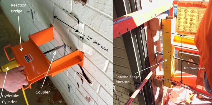
Figure 5 shows a 12-ton rated pull rig at the face and end of the wall used to pull test the anchors to failure. The pull rig reaction bridge has a clearance of 12 inches between supports to allow breakout as a possible failure mode. Using a reaction bridge extension increases the clear span to 18 inches. ASTM 488 requires a free span clearance of four times the embedment depth. This standard was not followed because exceeding the flexural bending capacity of the wall was a concern. In most cases a minimum clear span of at least three times the anchor embedment depth was met.
With the testing parameters in place, next week I’ll share the results of the tests.

Related Posts
 Part II: Tensile Performance of Simpson Strong-Tie® SET-XP® Adhesive in Reinforced Brick – Test Results
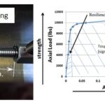 Understanding and Meeting the ACI 318 – 11 App. D Ductility Requirements – A Design Example
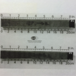 Changes Made to ACI 318 With Respect to Adhesives Anchors in Concrete: What Engineers Need to Know
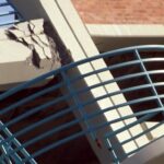 30 Years After Northridge: Lessons, Progress, and Community Resilience
I hate cliff-hangers… Looking forward to reading next week’s results!