

Hurricane season is in full swing, and we’ve had a record number of named storms to date. With each one, Mother Nature has taken the opportunity to remind us of her awesome power and teach us how we can improve our built environment in preparation for the next. One of the lessons we’re regularly reminded of is the importance of a successfully implemented continuous load path and its role in keeping a structure intact.
Much like my colleague Doug Allen, who recently recalled his experience doing damage assessments in the Bahamas after Hurricane Dorian last year, working for Simpson Strong-Tie has provided me with opportunities to witness first-hand the aftermath of several significant high-wind events. I’ve participated in a few post-event damage surveys, most recently in collaboration with the Structural Extreme Events Reconnaissance (StEER) Network after the Nashville area tornado in March of this year; and prior to that, in the Florida panhandle following Hurricane Michael. In this post, we’ll take a closer look at some examples of failed load path connections that I’ve observed, and review how we can best learn from Mother Nature’s lessons.
Defining a Continuous Load Path
Here at Simpson Strong-Tie, we’ve long emphasized the importance of providing a continuous load path and have many resources on this topic available to designers, contractors, and homeowners alike. Our High Wind Solutions site offers a wide variety of information ranging from software and drawings on the designers page to more homeowner-focused resources such as this infographic and Build Strong blog post that give a more general overview of what continuous load path means. This system of wood, metal connectors, fasteners and shearwalls that ties the entire frame together at critical points helps ensure that a home is capable of resisting seismic or wind loads. Our company mission is to help people build safer, stronger structures — and that starts with incorporating a continuous load path. It’s important to note, though, that this concept is not one invented by Simpson Strong-Tie, but rather a requirement taken directly from the International Building Code (IBC) and International Residential Code (IRC).
Be Direct
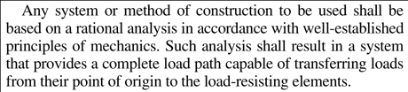
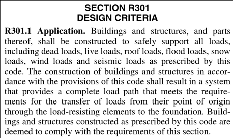
As we’ve seen, both the IBC and IRC require a continuous load path from a load’s point of origin through load-resisting elements all the way to the foundation. In the case of wind uplift, the load generally originates at the roof level, either from the overhang or through suction on the roofing and decking, then goes through the truss or rafter and into the top plate. This is fairly obvious and straightforward, but we must be careful to avoid becoming complacent when considering this simple concept and not underestimate the significance of these connections.
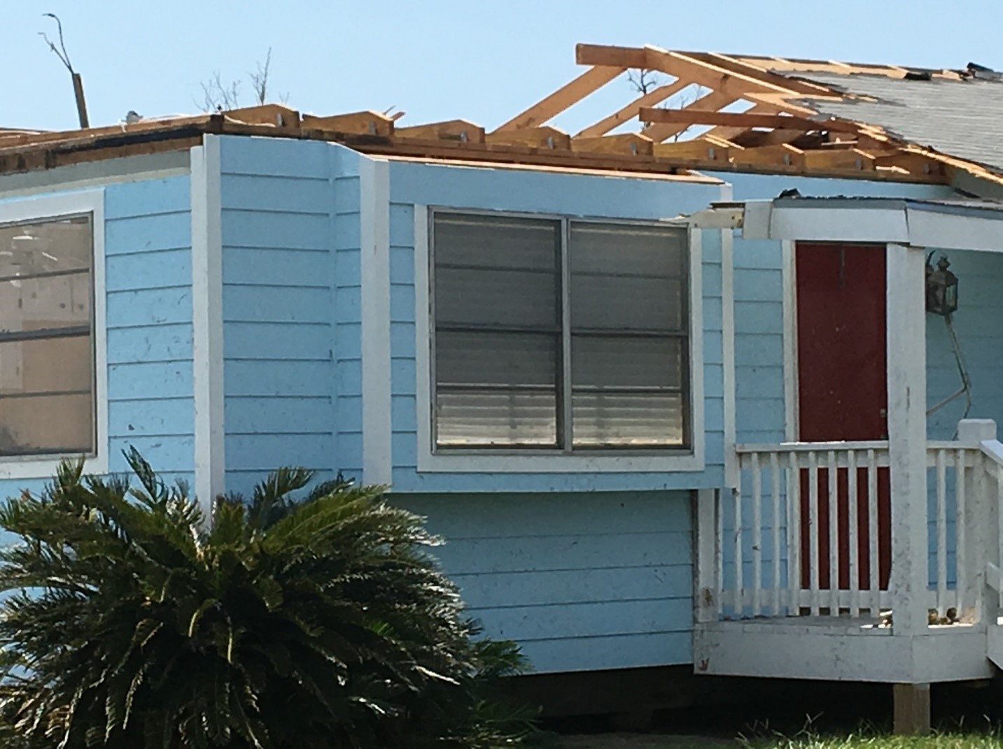
If we look closely at the roofline in the photo below, we can see hurricane ties attached to the ceiling joists, not the rafters. For homes built per the IRC, the heel joint connection between the roof rafters and ceiling joists is intended for resisting gravity loads, not uplift, and IRC Table R802.11 provides fastening requirements for the roof rafter to top plates, not ceiling joist to top plates. In the case of this home, this would have meant attaching the hurricane ties to the roof rafters, thereby excluding the ceiling joists from the load path altogether and creating a simpler, more direct load path.
Follow Published Installation Instructions
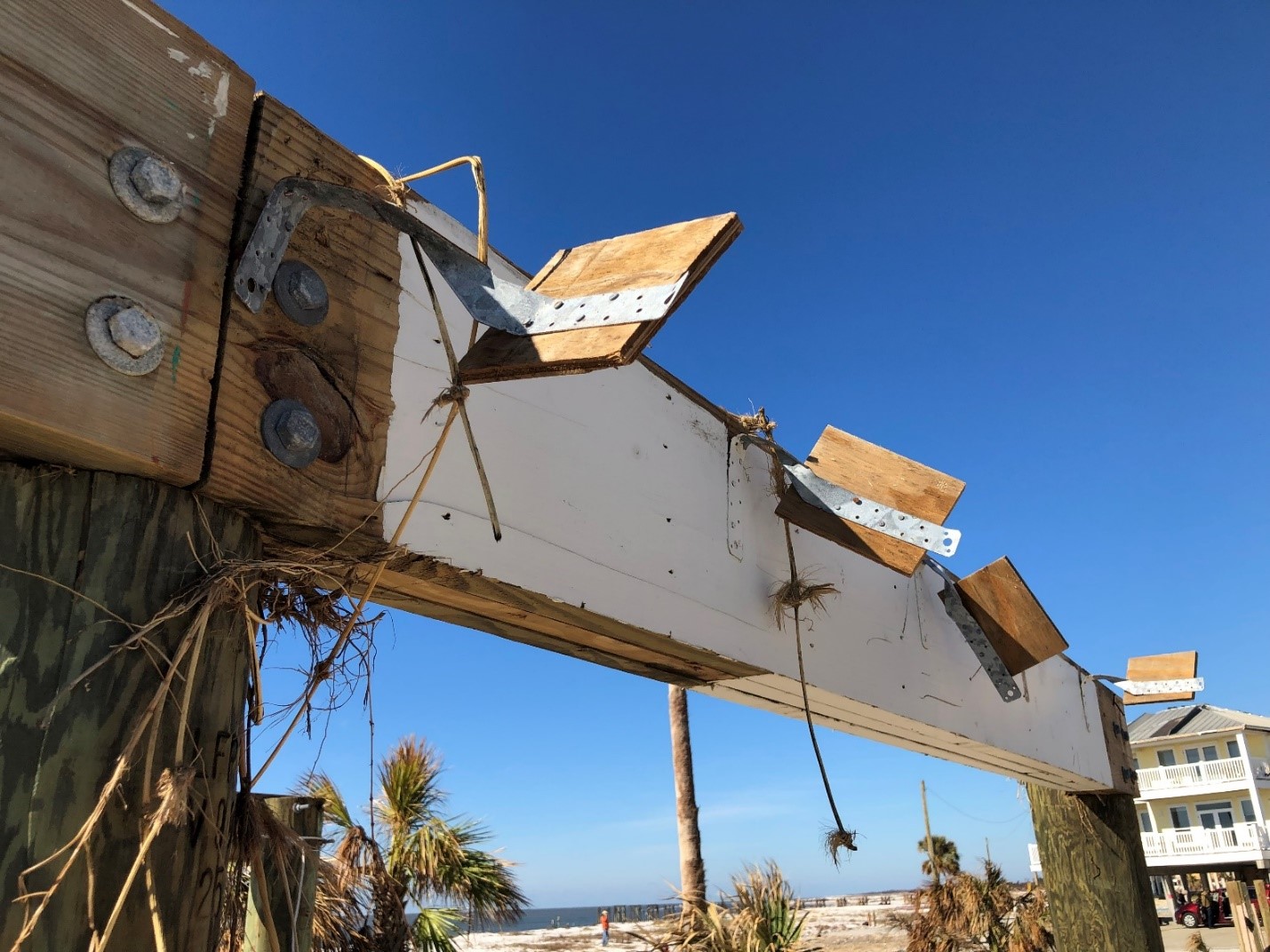
Much like a fully detailed and dimensioned bolted connection, manufactured products such as Simpson Strong-Tie connectors have installation requirements that must be met in order to achieve the published loads. One fairly common example of such a requirement is fastening of multiple plies or shims. When using shims between a member and connector, it’s required that the shim be fastened to the member independently of the connector fasteners (see Note m on p. 17 of our Wood Construction Connectors catalog).
Below is an example from an elevated coastal home where plywood shims were used between the twist straps and floor framing, and only the nails into the connector were installed. Since the plywood and floor framing weren’t fastened together independently, and only 1 1/2″-long nails were used, there was very little effective penetration into the primary floor framing. It’s no surprise then to see only the plywood remaining attached to the straps.
Don’t Stumble at the Finish Line
Any single connection within a continuous load path is just as important as the next. After all, a chain is only as strong as its weakest link. It’s interesting then how much more focus is given to the roof-to-wall connection. Why would that be? Structures sustaining wind damage tend to fail early on in the load path —close to where the load originates — which is most often the roof level. For this reason, roof-to-wall connection failures are much more frequently documented than other connection failures during damage assessments.
While the roof-to-wall connection is certainly important, don’t forget to follow the load path down the wall and take it to the finish line. This means properly tying top plates to studs and studs to the sill plate, installing adequate sill plate anchorage, and — depending on your foundation type — using reinforcing bars to take the load down to the footing.
In the photo below, you can see that only end nails were used to fasten studs to the sill plate, yet the presence of bearing plates and a reduced anchor bolt spacing indicate the designer was likely expecting some significant uplift forces.

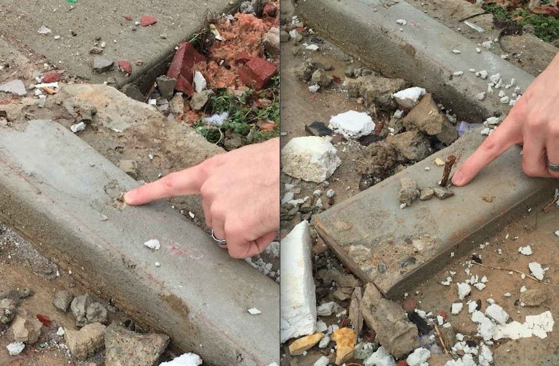
The IBC and IRC both require that a wood frame structure’s sill plate be anchored to the foundation using 1/2″-diameter bolts, with 5/8″ bolts required in some cases, at an embedment of at least 7″. Although both codes allow for alternative fastening methods, not all methods are adequate for use in a continuous load path. The following two photos demonstrate the result of improper anchorage of the sill plate to foundation. While cut nails and shot pins may be acceptable in some jurisdictions for anchoring interior, non-load-bearing walls or for temporary fastening of exterior walls, they are simply inadequate otherwise. The photo on the left shows a small divot in the curb, highlighting the poor penetration these methods provide. The photo on the right shows a cut nail still sticking straight up from the curb, which means the sill plate likely just lifted straight up over it, along with the rest of the wall framing above. Refer to the technical bulletin T-A-SILPLANCH for additional information on proper sill plate anchorage and some acceptable alternatives to the code-specified 1/2″-diameter anchor bolts.
Homes constructed with raised floors add another link to the load chain that will need to be accounted for in an adequate structural design. The following photos depict one such home that had a lack of rebar and grout within the cells of the CMU to transfer the load through the stem wall and into the footing. While the sill plate was anchored to the top course — you can actually see the CMU blocks that had anchor bolts in grouted cells still hanging on in the right-hand photo —there was no continuity to the foundation below.

It’s Not Always About Uplift
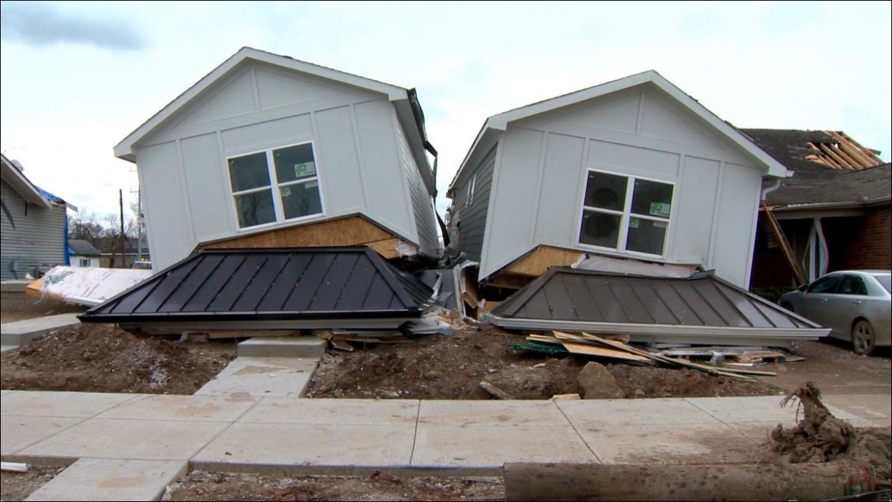
When designing for wind, our minds often go directly to uplift, but that’s not the only direction we should be thinking about. Remember — wind blows horizontally. If the structure is not adequately braced to resist lateral forces, what’s the point of designing for uplift? As design trends push for more windows and larger open spaces, solid walls become scarcer. These trends may be a good way of letting in lots of natural light, but they’re not necessarily good for resisting lateral wind pressures.
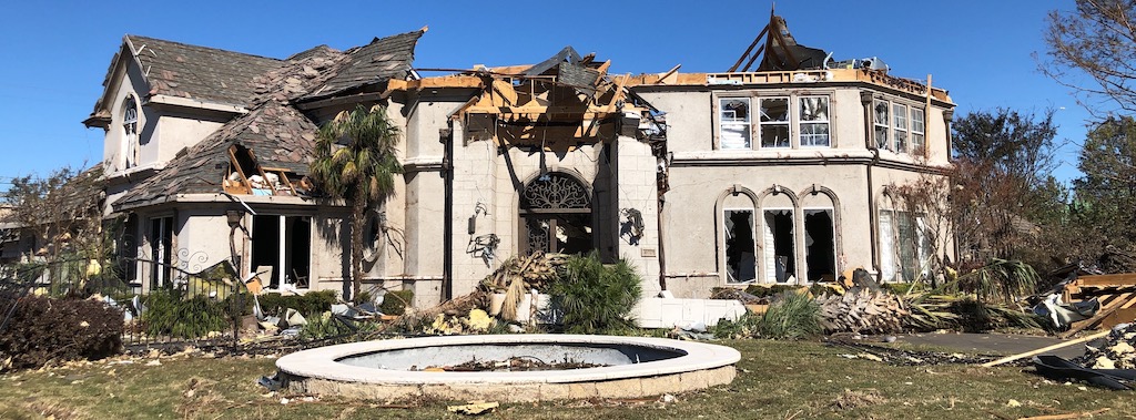
The homes shown in the photo below both had a very narrow footprint side-to-side with a large window and door on the lower level, which limited the amount of lateral bracing that could be provided. The structure had a soft-story type of failure where the lower level collapsed and the upper level remained relatively intact.
Follow the Load Path
Although the presence of connectors or anchors on a home typically correlates with an improvement in performance during a high-wind event, the photos shown here illustrate that simply installing them does not guarantee a structure’s survival. Care still needs to be taken in the detailing and installation of all connections making up the continuous load path because, as the saying goes, “A chain is only as strong as its weakest link.” When designing for a continuous load path, make sure to start at the top and follow the load path, looking for as direct a route as possible. Don’t forget to track the load through the load-resisting elements and ensure it goes all the way into the foundation. When using any proprietary products in your connections, follow the manufacturer’s installation instructions to ensure a sound connection capable of achieving the published load. And lastly, remember that a structure needs to be capable of resisting both uplift and lateral loads during a significant wind event. While this is by no means a solution to every lesson Mother Nature has to teach us, it’s a huge step in the right direction. By continually learning from past experiences and applying conscious effort to improve the way we design and build, we’ll make sure we’re better prepared for the next high-wind event.
If you’d like more information on this topic, we have a webinar titled “Choosing the Right Connections for Wind-Resistant Design,” which provides an overview of our new High Wind Guide, details a design example using the guide to select proper connections, and reviews the right connectors for use with other construction materials as well as for special connections. The recording is available here. Please also be sure to check out our High Wind Solutions page to find additional resources for building in high wind.
