IBC Section 1604.9 requires structural members, systems, components and cladding be designed to resist forces due to earthquakes and wind, with consideration of overturning, sliding and uplift. It also states that a continuous load path be provided for transmitting these forces to the foundation. Seems obvious to engineers that a continuous load path is needed, but it’s still nice to have the code say so.
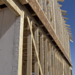 But what happens if your structure’s upper and lower story walls do not stack? How do you create the required continuous load path? As engineers, we try to steer the architect towards eliminating the offset, making things line up, and keeping construction simple. But architectural requirements cannot always accommodate simple, and non-stacking walls occur all the time.
Specifically, let’s consider an exterior wall where these offsets are usually due to architectural set-backs or cantilever conditions. Small offsets occur quite often in residential construction in areas that use a brick façade at the lower level, and siding or stucco is used at the upper level. Even this small – typically 5 ½” – offset can create havoc in shear and uplift load path connections. See below.
For a stacked wall condition, the uplift load path connection from the upper level to the lower may be as simple as a single strap connecting stud to stud. Add in a small cantilever, and the uplift load path requires four to five different connections to create to transfer the same uplift load. A longer cantilever of several feet would require a joist design considering both bending and shear induced into your floor system from the uplift as well.
Shear load will obviously need to be transferred from floor to floor as well, and again more steps are required to create this load path in a cantilevered floor system. See below for an example of shear and uplift load path connections with a cantilevered i-joist floor system.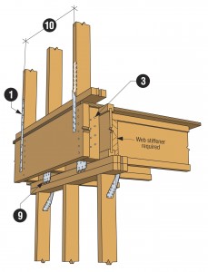
 The detailing of this load path also changes based on what type of floor system you have (floor truss, I-joists, solid-sawn joists). Check out the Simpson Strong-Tie Connection Solutions for Cantilevered Floors technical bulletin for more information on connection solutions for cantilevered floor conditions.
How have you handled these load path questions in your structural design? Please share a comment and let me know!
– Paul
What are your thoughts? Visit the blog and leave a comment!

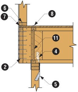



I used to have a good size beam or a min of 1.75″x LVL under the upper wall for the whole length of the upper wall if possible to receive multiple shear wall overturning loads. This beam is attached to the ends of cantilevered fl jsts with upside down hangers, which becomes a rim jst for the cantilevered jsts. Then I have one beam in the floor at each end of this beam to support this beam for overturning loads and transfer it to the foundation as you show in your sketch. It’s a time consuming effort, because I always check it for Em requirements. I call this beam an elevated foundation. You just imagine this beam is supported at two ends only with uniform and multiple shear wall overturning loads on it, and make sure it’s stiff enough not to have a big deflection under all loading combinations