

This year the NASCC (North American Steel Construction Conference) will be in Baltimore, Maryland. The conference is the annual educational and networking event for the structural steel industry, which attracts attendees and exhibitors from all over the world. With more than 130 sessions this year, the conference will provide attendees the opportunity to learn the latest in research, design, technology and best practice in the steel industry.
Continue Reading
Author: Damon Ho
Damon is the Segment Market Manager for Prefabricated Lateral Systems. He received his B.S. in Architectural Engineering and MBA from Cal Poly, San Luis Obispo. After practicing Structural Engineering, he went on to obtain his Masters in Civil Engineering from University of Canterbury, New Zealand. Before joining Simpson Strong-Tie, Damon was a member of the Cal Poly, Architectural Engineering faculty from 2001 until 2007. He is a registered Professional Engineer in the state of California. When not at work, Damon enjoys cooking and camping with his family.
Changes in IBC from 2009 to 2012: Seismic Design
The transition from one building code to the next always begs the question, “how is the newer code different?” There are several changes between the 2009 IBC and 2012 IBC that will change the way designers approach seismic design. This blog post is a broad overview of some of the changes. Since it’s not practical to cover all the changes between the previous and new codes in detail in one post, the discussion will be mainly on 2012 IBC and the corresponding ASCE7-10 reference standard.
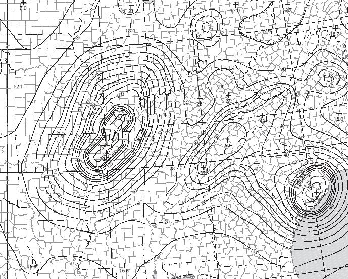
The seismic ground motion maps have been updated to match ASCE7-10. The titles of the maps in IBC were revised from “Maximum Considered Earthquake Ground Motion” to “Risk-Targeted Maximum Considered Earthquake (MCER) Ground Motion Response Accelerations” in order to reflect the titles in 2009 NEHRP and ASCE 7-10. As in previous editions, some areas will prove difficult to read due to the contour lines, so the USGS site and GPS coordinates are recommended (http://earthquake.usgs.gov). Additional information about changes made for 2009 NEHRP is available at www.nibs.org or www.bssconline.org.
The term “occupancy category” was replaced with “risk category” in the 2012 IBC for consistency with the term used in ASCE 7-10. This change was made because it was decided that the use of the word “occupancy” implied the category was directly tied to occupancy classifications in the code, while the word “risk” more accurately communicates that the category is based on acceptable risk of failure.
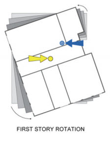
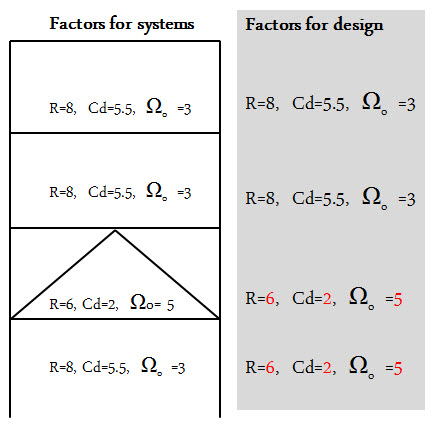 ASCE7-10 revised the way designers use the corresponding Drift amplification, Cd, and Overstrength factor, Ωo, of the Response modification factor, R. In ASCE7-05, when there is a vertical combination of different R-values, the Cd, and Ωo cannot decrease as you go down each level of a building. In ASCE7-10 (12.2.3.1), the Cd and Ωo always correspond to the R-Value as you go down. The adjacent figure illustrates the new provision to use the corresponding Cd, and Ωo with the R-value at each level.
ASCE7-10 (12.3.4.1) added a clarification for out-of-plane anchorage forces where the redundancy factor, p = 1.0. The intent of the redundancy factor was to ensure the vertical seismic-resisting system with insufficient redundancy had adequate strength. The design forces for out-of-plane wall loading are not redundancy requirements. ASCE7-10 (12.11.12) revised the out-of-plane wall anchorage force equation where the anchorage forces are reduced for shorter diaphragm spans.
 Light-frame construction structures are no longer exempt from amplification of accidental torsion in ASCE7-10 (12.8.4.3). There are many structures vulnerable to torsional effects including some “tuck under” parking buildings that are often light-frame structures. See posts titled Soft-Story Retrofits and City of San Francisco Implements Soft-Story Retrofit Ordinance for more discussion of soft-story, light-frame buildings.
This is just a brief summary of changes related to seismic design found in the 2012 IBC. What are other changes that will modify your approach to seismic design?

Use of Holdowns During Shearwall Assembly
When designing a shearwall according to the International Building Code (IBC), a holdown connector is used to resist the overturning moment due to lateral loading. From a structural statics point of view, a shearwall without dead load or holdowns would have zero lateral-resisting capacity without any restraint to resist the overturning moment. Since the wall assembly still has the sill plate anchorage providing resistance to overturning, testing can measure the capacity of a wall assembly without holdowns.