Plated Wood Truss Hip End Styles

For many, the first day of summer means it is time to cinch up your favorite hip-hugging bathing suit and enjoy the warm weather. For the truss industry, it’s time to keep those hip-hugging bathing suits in the closet and take advantage of the favorable weather months by bidding and building as many jobs as possible. During the bid and build frenzy, there will be several hip end jobs leaving truss yards across the country, but what exactly is a hip end and what are the different styles?

Truss hip ends drawing
Roof with Multiple Hip Ends (blue), Plan View

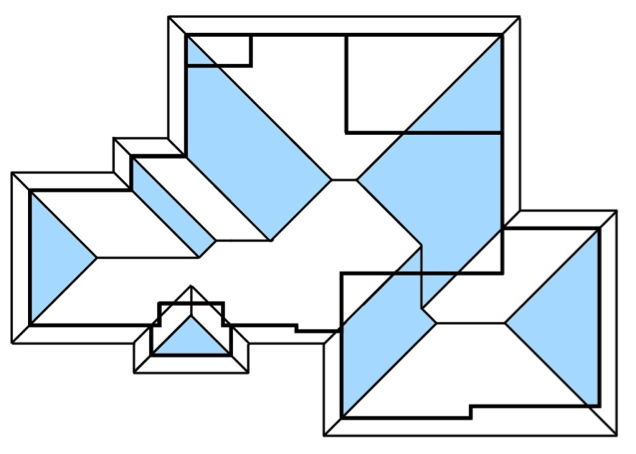
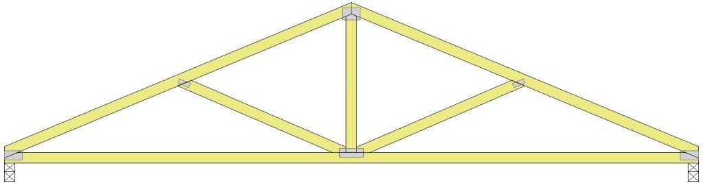
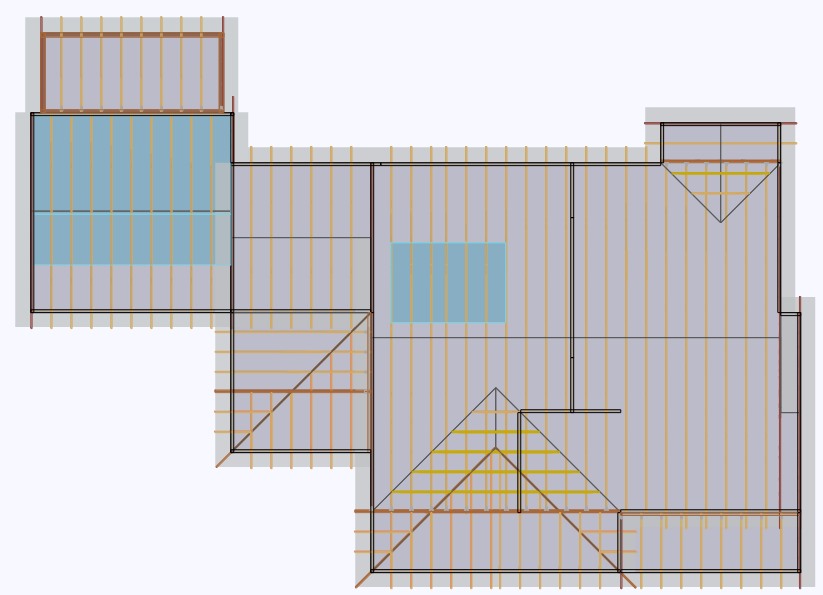
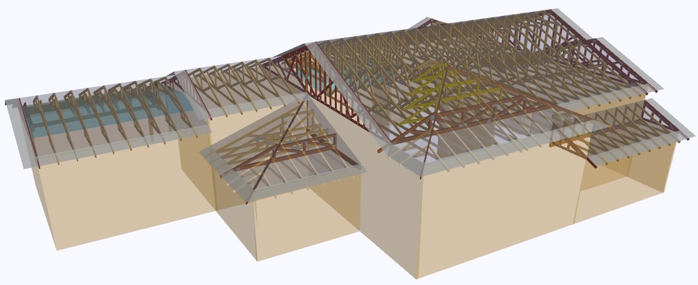
The Structural Building Components Association website (SBCA) defines a hip roof as a “Roof system in which the slope of the roof at the end walls of the building is perpendicular to the slope of the roof along the sides of the building.” While framing terms differ by region, most trussed hip end systems will include hip trusses, jack trusses (end and side) and a rafter or corner girder truss. Hip end style and setback (distance from side or end walls to the hip girder truss) may also vary by building design and region.

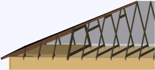
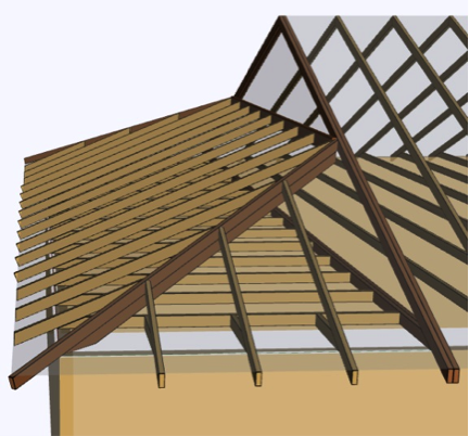
In the western part of the country, a California Hip system is typically seen in many trussed structures. In this hip system, the hip truss flat top chord is dropped by the plumb cut of the jack top chord at the roof pitch. By doing this, the top chords of the end jack trusses can pass over and bear on the dropped flat top chords. As the height of the hip end roof plane increases, the height of the flat top chord also increases, though the interval at which the flat top chord height increases may vary by building design and region.

Truss Design: California Hip System
California Hip System, Plan View
Truss Design: California Hip Rendering
California Hip System, Rendering

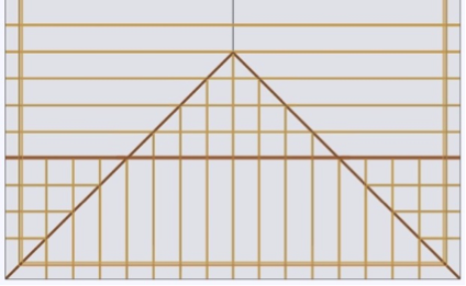
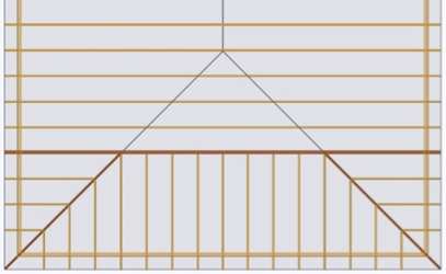
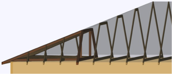
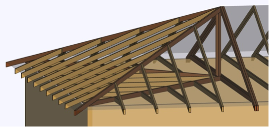
East of the Rocky Mountains, the California Hip is rare and a Step-Down Hip system is more popular. Differing from the California Hip, a Step-Down Hip system is one where every truss under the hip end plane decreases in height, or “steps down” from the apex until it reaches the hip girder, which is placed at a pre-determined setback.

Step Down Hip System, Plan View
Step Down Hip System, Rendering

Less regional and more situational depending on the building design, are the Lay-In Gable, Dutch and Terminal Hip systems. The Lay-In Gable Hip system is one with many regional names and shares similarities with the California and Step Hip systems. Like the Step Hip, every truss steps down moving from the apex to the setback. Like the California, every truss flat top chord has a drop. However, the flat top chord is dropped by the plumb cut of a 1.5” member at the roof pitch, as the gable frame lays flat.

Roof System: Lay-In Gable Hip System, Plan View
Lay-In Gable Hip System, Plan View (Gable Frame shown in green for clarity)


Lay-In Gable Hip System, Rendering

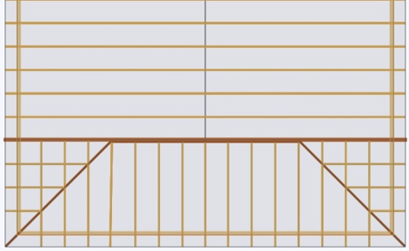
In a Dutch Hip system, the hip end roof plane does not converge with the side planes to form an apex. Instead, the hip end plane pitches directly into the girder truss that is placed at a predetermined setback. Jack trusses then connect to the hip girder truss or to a ledger attached to the hip girder truss.  This hip system is also referred to as a Dutch Gable.

Dutch Hip System, Plan View
Dutch Hip System, Rendering

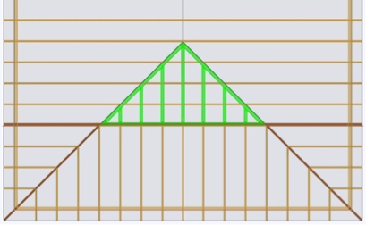
Assuming like roof pitches and heel heights, a Terminal Hip system is one where the hip girder truss setback is half of the main truss span or building width. If pitches and heel heights vary, the girder truss is placed at the apex of the three converging roof planes, which could be more or less than half of the main truss span or building width.

Terminal Hip System, Plan View
Terminal Hip System, Plan Rendering
Terminal Hip System, Plan Rendering 

While these are some common hip end styles in the truss industry, there are definitely others. Each style has its own advantages and disadvantages, and a discussion of those will be the topic of a future post.

What other types of hip end styles are you familiar with? Let us know in the comment section below.

Plated Wood Truss Design Responsibilities

When the opportunity presents itself, glance up at the ceiling. Do you ever wonder who the responsible parties were for the design and construction of the roof above? If you’re involved in the truss industry, there is no doubt you have. If not, it never hurts to be in the know. Since we spend a significant portion of our life under a roof, it helps to know a few facts about what’s over our heads.

Truss drawing
Truss drawing

Roofs built from prefabricated wood trusses used in light-frame and residential construction will be the focus of this blog post.

The current national design standard for metal plate connected wood truss construction is ANSI/TPI 1-2007, which is the referenced standard in the 2009 and 2012 IBC and IRC. So what are design responsibilities for wood trusses and why are they important? They are a series of responsibilities required by key parties for applications of trusses in the construction of a building. These key parties (Owner, Building Designer, Registered Design Professional, etc.) are important because each is required to produce pertinent information about the truss and truss system from its inception to erection and long in-service life.

Plan
Plan
Rendering of Trusses

As wood trusses have evolved, so have publications about their construction, quality and use.  The first standard was published in 1960, with subsequent standards published periodically.

In 1995, the Truss Plate Institute (TPI) published ANSI/TPI 1-1995, which served as the first ANSI consensus-based national design standard for metal-plate connected wood truss construction. One of many new chapters established in ANSI/TPI 1-1995 was chapter 2, identifying design responsibilities. While early versions of ANSI/TPI 1 introduced design responsibilities, chapter 2 of ANSI/TPI -2007 has clarified and added areas of responsibility that are vital for today’s component industry. In addition, the 2007 edition defined responsibilities regarding temporary and permanent restraint and bracing, and special inspection requirements to long span trusses (any truss with a span of 60 feet or greater). These are just a few, yet critical additions to the standard.

Without clear definitions of responsibility, how would the industry know who specifies truss connections, or who provides bracing locations necessary to a roof assembly and its duration of service? Additionally, who determines if a project requires a truss submittal package, or the type of information it must provide? While these questions and more are answered in ANSI/TPI 1-2007, any provisions of the TPI 1 Design Responsibilities can be changed in the contract documents for a given project, so long as all parties are made aware of and agree to the revisions.

Ensuring all parties’ know and follow the design standard can help ensure a properly designed, manufactured and erected truss that will lead to a safe roof system. If you’re a component manufacturer, knowing what you’re responsible for and required to produce can get you out of a jam or better yet, help you avoid one altogether. Communication is key to the industry. The Commentary and Appendices of ANSI/TPI 1-2007 is available for web review: http://www.tpinst.org/technical-downloads

ANSI TPI 1
ANSI TPI 1

Do you know or want to know the answers to the above questions? Or perhaps think there are responsibilities that need to be clarified or added to future publications of ANSI/TPI 1? Let us know in the comment section below.