

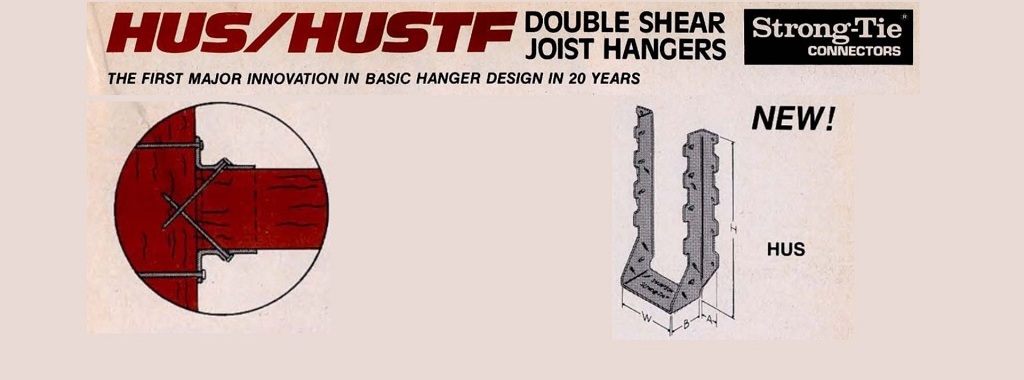
The first double shear hanger was the HUS, which appeared on the cover of the 1984 connector catalog. (Sorry that the image is a little dark. Thankfully, our photography and art design have improved over the last several decades.)
Tag: truss
Snow Loading for Trusses: Why Specifying a Roof Snow Load Isn’t Enough
 You might wonder what a quote about winning basketball games could possibly have to do with snow loading on trusses. As with basketball, the importance of close teamwork also applies to a project involving metal-plate-connected wood trusses – for the best outcome, the whole team needs to be on the same page. For purposes of this blog post, the team includes the Building Designer, the Truss Designer and the Building Official, and the desired outcome is not a win per se, but rather properly loaded trusses. Snow loading on trusses is one area where things may not always go according to the game plan when everyone isn’t in accord. This post will explain how to avoid some common miscommunications about truss loading.
Roof Framing: Building Strong Stick-Frame Roofs
Although truss-designed roofs are predominant throughout most of the residential construction industry, there are regions where building with stick-frame roofs is still common. In this post, Randy Shackelford discusses some design choices available to stick-frame builders, the challenges they pose, and the solutions offered by the Simpson Strong-Tie® connector system for stick-frame roofing. The post will also discuss some changes in the 2021 IRC that affect construction of stick-frame roofs.

What Building Professionals Need to Know About Construction Loading
Understanding construction loading is important as it relates to the acceptable practices in terms of staging and storing construction materials prior to installation. What does “construction loading” mean? This term describes materials and people that are present during the course of construction. It refers to any construction material that is stacked and/or staged on the trusses for any length of time prior to the installation of said materials. This also includes those individuals that are working or walking on the trusses during the course of construction.

How to Pick a Connector Series – Truss Hangers
In our second blog in the “How to Pick a Connector Series,” Randy Shackelford discussed the various considerations involved in selecting a joist hanger. So why is this blog post about truss hangers? A hanger is a hanger, right? Before I moved into the Engineering Department at Simpson Strong-Tie, I was the product manager for our Plated Truss product line. I can assure you that there is a bit more that goes into the selection (and design) of a truss hanger than does into selecting a joist hanger!
Of course, all of the considerations that were covered in the joist hanger blog apply to truss hangers as well. This blog post is going to discuss some additional considerations that come into play in selecting a hanger for a truss rather than a joist, and how some hangers have features designed especially for trusses.
The first (and most obvious) truss-specific consideration is the presence of webs. Because of truss webs, top-flange hangers are not as conducive to truss applications as they are to joist applications. A better alternative for trusses is an adjustable-strap hanger that can be installed as a top-flange hanger or face-mount hanger. Take the THA29, for example, Simpson’s first hanger developed specifically for the truss industry (circa 1984). It can accommodate different girder bottom chord depths, which eliminates the need for multiple SKUs, and the straps can be field-formed over the top of the girder bottom chord to reduce the number of fasteners (just like top-flange hangers). When a web member is in the way of the top-flange installation method, the straps can be attached vertically to the web in a face-mount installation instead.
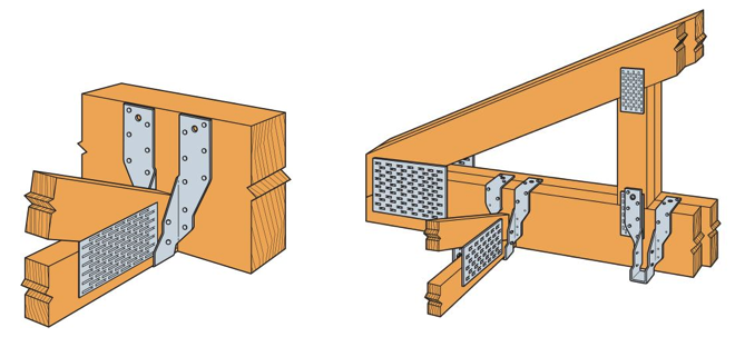
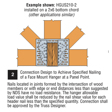
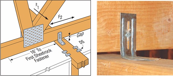
What if the web at that location isn’t vertical? You can still install the strap onto the web, but if any nails land in the joint lines formed by the intersection of the wood members, they cannot be considered effective. Therefore, the hanger allowable load may need to be reduced to account for ineffective header nails. This alternative installation is acceptable for any face-mount hanger located at a panel point as shown in our catalog (see detail below).
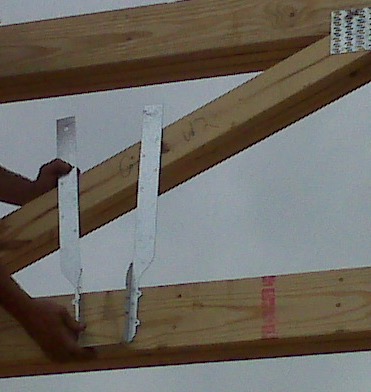
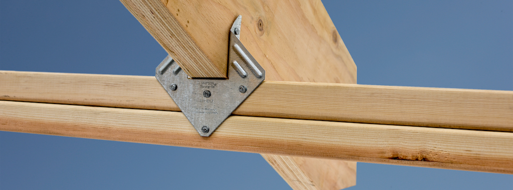
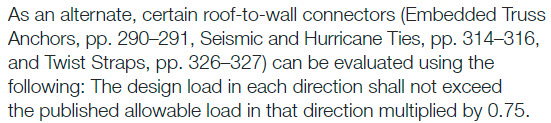
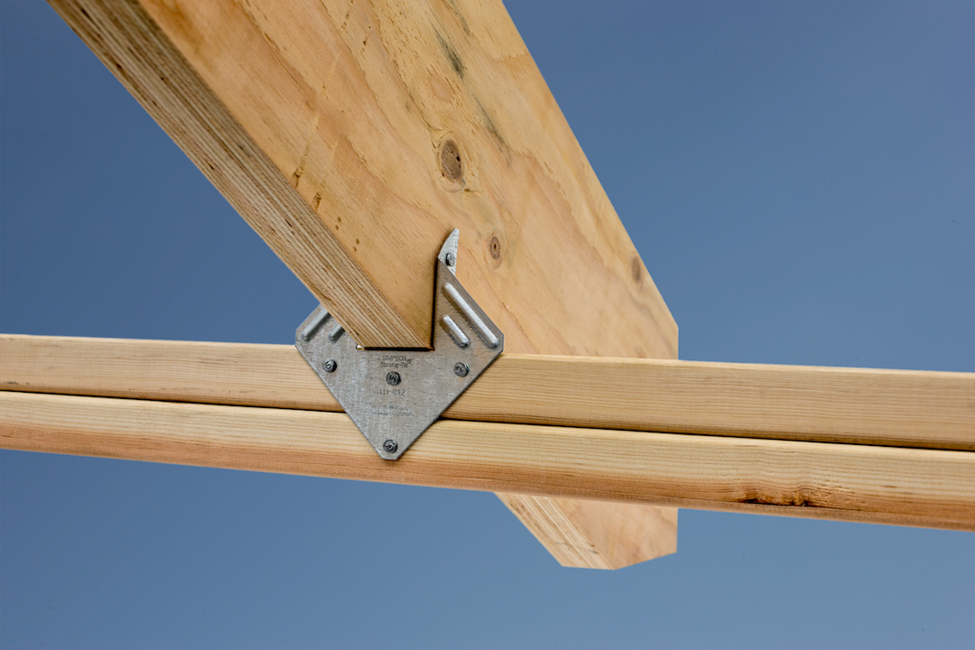
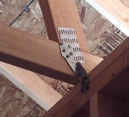
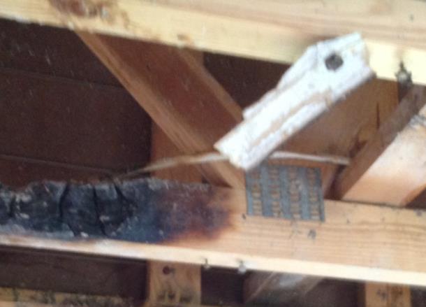
Although very versatile, not all adjustable-strap hangers can be installed on all sizes of bottom chords. Our catalog specifies a C-dimension for these hangers, which corresponds to the height of the side-nailing flanges. If that dimension exceeds the height of the bottom chord, then the straps cannot be field-formed as needed for the top-flange installation. And if the hanger isn’t located at a panel point, nailing the straps to any diagonal web that the straps can reach (see photo below) is not an acceptable option!
Another unique consideration that goes into the selection of a truss hanger is the heel height of the carried truss. A truss with a short heel height installed into a tall hanger will likely leave air (or “daylight,” as I call it) behind a lot of the nail holes running up the side flanges. When nail holes in a hanger have air behind them instead of wood, this equates to a reduction in hanger capacity. So when the carried truss has a heel height that is much less than the depth of the carrying member (and the hanger), it is important to use the appropriate hanger capacity for that condition and not overestimate the hanger’s capacity. Refer to our technical bulletin T-REDHEEL for allowable loads for reduced heel height conditions.

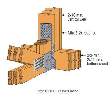
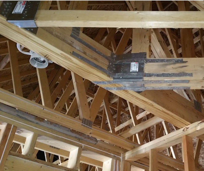
Because trusses are capable of carrying a lot of load – and producing large reactions – hangers for truss applications often require larger capacities than joist hangers. Unfortunately, there is only so much capacity that can be achieved from a hanger that fits entirely onto a girder truss bottom chord. Therefore, in order to use our highest load-rated truss hangers, a properly located vertical web is required, and the web must be wide enough for the hanger’s required face fasteners and minimum edge distances. The more capacity that is required, the more fasteners it takes, and the wider the vertical web must be. Our highest-load-rated truss hanger that installs with screws is the HTHGQ. It has a maximum download capacity of 20,735 lb., but it requires a minimum 2×10 vertical web. The THGQ/THGQH series can be installed onto as small as a 2×6 web, but the maximum possible capacity on a 2×6 web is 9,140 lb.
In addition to high-capacity hangers, truss applications often require high-capacity skewed hangers. When selecting skewed hangers, it’s important to realize that hangers with custom skew options usually have a reduction that must be applied to the hanger’s 90-degree capacity. Another important factor that is sometimes overlooked in the selection of skewed hangers is whether the carried member is square-cut or bevel-cut. When the member is square cut – as in the case of trusses – not only does this typically result in a greater reduction in capacity, but some skewed hangers cannot be used at all with square-cut members. For example, the fastener holes on the side flange may not be located far enough away from the header to accommodate square-cut members. See the photo below for an example of what can happen if a skewed hanger that is intended for a bevel-cut member is used for a truss.

As discussed in the previous hanger blog, face-mount hangers offer the advantage of being installed after the joist (or truss) is installed. What if the truss is installed prior to the hanger and a gap exists between the truss and the carrying member? In that case, the best option may be to select a truss hanger that was designed with this type of installation tolerance in mind, the HTU hanger. Other face-mount truss hangers that use double-shear nailing are great when gaps are limited to ⅛” or less, but their capacities take a pretty large hit when the gap exceeds ⅛” (see our previous blog Minding the Gap in Hangers for more information). The HTU was designed to give an allowable load for up to a ½” gap between the end of the truss and the carrying member. In addition, it has built-in nailing options to accommodate short heel heights even in the taller models – definitely a truss hanger!

Finally, there is one more thing to consider when selecting a face-mount hanger for a truss application, which relates to how tall the carrying member is compared to the hanger. Assuming the bottom of the hanger will be installed flush with the bottom of the girder bottom chord, a hanger that is much shorter than the bottom chord will induce tension perpendicular to the grain in the chord. Due to wood’s inherent weakness in perpendicular-to-grain tension, a hanger that is too short may limit the amount of load that can be transferred– to something less than the hanger’s published allowable load. Therefore, it isn’t enough to check whether the hanger fits on the bottom chord; the hanger must also cover enough depth of the chord to effectively transfer the load (or else the allowable hanger load may need to be reduced to the member’s allowable cross-grain tension limit).
Cross-grain tension is not a truss-specific issue, but because it is an explicit design provision in the truss design standard (TPI 1), it is a necessary consideration to mention in a discussion about truss hanger selection. In fact, proper detailing for cross-grain tension in different wood applications could be a future topic in and of itself.
Add to all this the specialty truss hangers that can carry two, three, four, and even five trusses framing into one location, and it is no wonder that there is an entire section in our catalog that is dedicated to truss hangers. Are there any other truss hanger needs that you would like to discuss? Please let us know in the comments below!
How to Select a Connector – Hurricane Tie
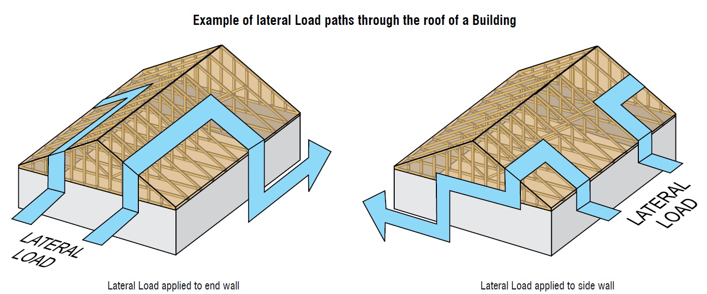
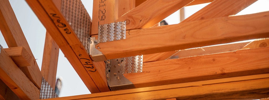
When it comes to wood-frame construction, hurricane ties are among the most commonly specified connectors. They play a critical role in a structure’s continuous load path and may be used in a variety of applications, like attaching roof framing members to the supporting wall top plate(s), or tying wall top or bottom plates to the studs. They are most commonly used to resist uplift forces, but depending on regional design and construction practices, hurricane ties may also resist lateral loads that act in- or out-of-plane in relation to the wall.
Simpson Strong-Tie manufactures approximately 20 different models of hurricane ties, not counting twist straps, other clips, or the new fully-threaded SDWC screws often used in the same applications. This assortment of models raises the question, “How do you select the right one?”
In this post, we’ll outline some of the key elements to consider when selecting a hurricane tie for your project.
Demand Load
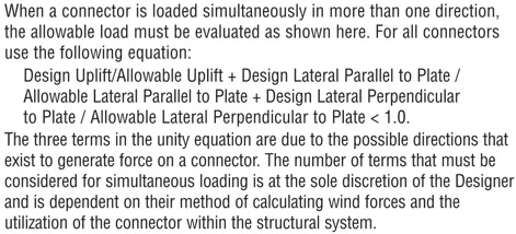
Let’s start with the obvious one. If your building’s roof trusses have an uplift of 600 lb. at each end, don’t select a hurricane tie with a published capacity of less than 600 lb. It’s also important to consider combined loading if you plan to use the tie to resist both uplift and lateral loads. When the connector is resisting lateral loads, its capacity to resist uplift is reduced. I won’t go into too much detail on this topic since it was covered in a recent blog post, but in lieu of the traditional unity equation shown in Figure 1, certain Simpson Strong-Tie connectors (hurricane ties included) are permitted to use the alternative approach outlined in Figure 2.
What if the tabulated loads in the catalog for a single connector just aren’t enough? Use multiple connectors! An important note on using multiple connectors, though: Using four hurricane ties doesn’t always mean you’ll get 4x the load. Check out the recently updated F-C-HWG23 High Wind Guide for allowable loads using multiple connectors and for guidance on the proper placement of connectors so as to avoid potential overlap or fastener interference.


Dimensional Requirements
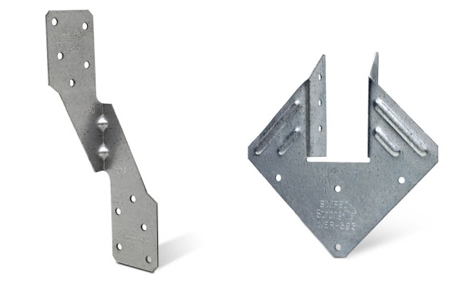
While the majority of the hurricane ties that Simpson Strong-Tie offers are one-sided (such as the H2.5A), some are designed so the truss or rafter fits inside a “U” shape design to allow for fastening from both sides (such as the H1). If using the latter, make sure the width of the truss or rafter is suitable for the width of the opening in the hurricane tie. For example, use our new H1.81Z (not the H1Z) for 1¾” wide engineered roof framing members.
Additionally, the height of the hurricane tie and the wood members being attached should be compatible. For example, an H2.5A would not be compatible with a roof truss configured with only a nominal 2×4 bottom chord over the plate since the two upper nail holes in the H2.5A will miss the 2×4 bottom chord (see Figure 7). This is actually such a common mis-installation that we specifically tested this scenario and have a specific footnote in the table load about it (note the greatly reduced capacity). In this case the ideal choice would be the H2.5T, which has been specifically designed for a 2×4 truss bottom chord.

Fasteners with Hurricane Ties
It’s also essential to pay close attention to the diameter and length of the fasteners specified in the Simpson Strong-Tie literature. While many hurricane ties have been evaluated with 8d x 1½” nails for compatibility with nominal 2x roof framing, some require the use of a longer, 8d common (2½” long) nail and others require a larger-diameter 10d nail.
When specifying products for a continuous load path, it’s a good idea to select connectors that all use the same size nail to avoid improper installations on the job. It’s much easier if the installer doesn’t need to worry about which size nail he currently has loaded in his pneumatic nailer.
Wall Framing
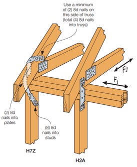
Do your roof and wall framing members line up? If so, creating a continuous load path can be made simpler by using a single hurricane tie to fasten the roof framing to studs. The H2A, H7Z, and H10S are some of the connectors designed to do just that. If your framing doesn’t align, though, you can use two connectors to complete the load path. For simplification and to reduce potential mix-ups in the field, consider selecting the same hurricane tie for your roof framing-to-top-plate and top plate-to-stud connections, like the H2.5A.
Besides the added benefit of fewer connectors to install, using a single hurricane tie from your roof framing to your wall studs can eliminate top-plate roll, a topic discussed at length in one of our technical bulletins.
Other Factors When Selecting Hurricane Ties
Some additional factors that may influence your selection of a hurricane tie are:
- Environmental factors and corrosion should be considered when selecting any product. Nearly every hurricane tie is available in ZMAX®, our heavier zinc galvanized coating, and several are available in Type 316 stainless steel. A full list of products available in ZMAX or stainless steel may be found on our website. On a related note, be sure to use a fastener with a finish similar to that of the hurricane tie in order to avoid galvanic corrosion caused by contact between dissimilar metals.
- When retrofitting an existing structure, local jurisdiction requirements will also influence your decision on which hurricane tie to use. As an example, the state of Florida has very specific requirements for roof retrofitting, which we outline in a technical bulletin, and they specifically mention the roof-to-wall connection. Be sure to check with your local city, county or state for specific requirements before you decide to retrofit.
- Availability of wind insurance discounts in your area could also affect your decision on which type of hurricane tie to use on your home. Your insurance company may provide a greater discount on your annual premium for ties that wrap over the top of your roof framing and are installed with a certain minimum quantity of nails. Check with your insurance provider for additional information and requirements.
Although this is a lot to take in, hopefully it makes choosing the right hurricane tie easier for you on your next project. Are there any other items you consider in your design that weren’t mentioned above? Let us know in the comments below.

Simultaneous Loading on Hurricane Ties
“Structures are connections held together by members” (Hardy Cross)
I heard this quote recently during a presentation at the Midwest Wood Solutions Fair. I had to write it down for future reference because of course, all of us here at Simpson Strong-Tie are pretty passionate about connections. I figured it wouldn’t take too long before I’d find an opportunity to use it. So when I started to write this blog post about the proper selection of a truss-to-wall connection, I knew I had found my opportunity – how fitting this quote is!
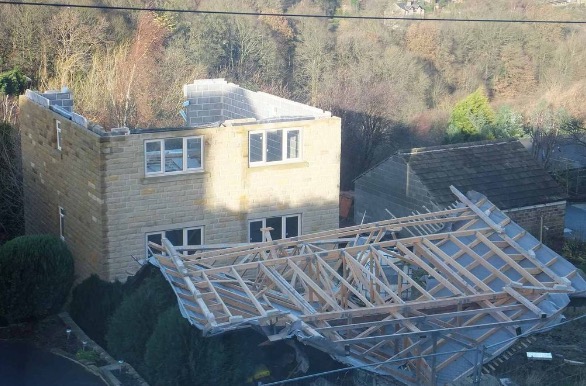
There are plenty of photos of damage wrought by past hurricanes to prove that the connection between the roof and the structure is a critical detail. In a previous blog post, I wrote about whose responsibility it is to specify a truss-to-wall connection (hint: it’s not the truss Designer’s). This blog post is going to focus on the proper specification of a truss-to-wall connection, the methods for evaluating those connections under combined loading and a little background on those methods (i.e., the fun stuff for engineers).
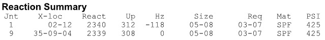
Take a quick look at a truss design drawing, and you will see a reaction summary that specifies the downward reaction, uplift and a horizontal reaction (if applicable) at each bearing location. Some people are tempted to look only at the uplift reaction, go to a catalog or web app, and find the lowest-cost hurricane tie with a capacity that meets or barely exceeds the uplift reaction.
However, if uplift was the only loading that needed to be resisted by a hurricane tie, why would we publish all those F1 and F2 allowable loads in our catalog?

Of course, many of you know that those F1 and F2 allowable loads are used to resist the lateral loads acting on the end and side walls of the building, which are in addition to the uplift forces. Therefore, it is not adequate to select a hurricane tie based on uplift reactions alone.
Where does one get the lateral loads parallel and perpendicular to the plate which must be resisted by the truss-to-wall connection? Definitely not from the truss design drawing! Unless otherwise noted, the horizontal reaction on a truss design should not be confused with a lateral reaction due to the wind acting on the walls – it is simply a horizontal reaction due to the wind load (or a drag load) being applied to the truss profile. It is also important to note that any truss-to-wall connection specified on a truss design drawing was most likely selected based on the uplift reaction alone. There may even be a note that says the connection is for “uplift only” and does not consider lateral loads. In this case, unless additional consideration is made for the lateral loads, the use of that connector alone would be inadequate.
Say, for example, that the uplift and lateral/shear load requirements for a truss-to-wall connection are as follows:
Uplift = 795 lb.
Shear (parallel-to-wall) = 185 lb. (F1)
Lateral (perp-to-wall) = 135 lb. (F2)
Based on those demand loads, will an H10A work?
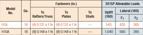
An initial look at the H10A’s allowable loads suggests it might be adequate. However, when these loads are entered into the Connector-Selector, no H10A solution is found.
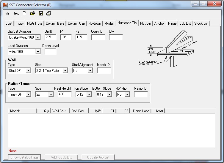
Why? Because Connector-Selector is evaluating the connector for simultaneous loading in more than one direction using a traditional linear interaction equation approach as specified in our catalog:
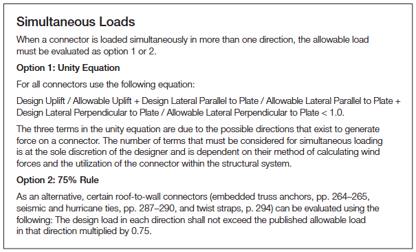
If the shear and lateral forces were to be resisted by another means, such that the H10A only had to resist the 795 lb. of uplift, then it would be an adequate connector for the job. For example, the F1 load might be resisted with blocking and RBC clips, and the F2 loads might be resisted with toe-nails that are used to attach the truss to the wall prior to the installation of the H10A connectors. However, if all three loads need to be resisted by the same connector, then the H10A is not adequate according to the linear interaction equation.

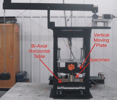
Some might question how valid this method of evaluation is – Is it necessary? Is it adequate? How do we know? And that is where the interesting information comes in. Several years ago, Simpson Strong-Tie partnered with Clemson University on an experimental study with the following primary objectives:
1. To verify the perceived notion that the capacity of the connector is reduced when loaded in more than one direction and that the linear interaction equation is conservative in acknowledging this combined load effect.
2. To propose an alternative, more efficient method if possible.
Three types of metal connectors were selected for this study – the H2.5A, H10, and the META20 strap – based on their different characteristics and ability to represent general classes of connectors. The connectors were subjected to uni-axial, bi-axial and tri-axial loads and the normalized capacities of the connectors were plotted along with different interaction/design surfaces.
These interaction plots were used to visualize and parameterize the combined load effect on the capacity of the connectors. The three different interaction plots that were examined were the traditional linear relationship, a quadratic interaction surface and a cuboid design space.
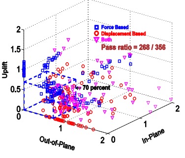
The results? Not only was the use of the linear interaction equation justified by this study, but a new, more efficient cuboid design surface was also identified. It provides twice the usable design space of the surface currently used for tri-axial loading and still provides for a safe design (and for the bi-axial case, it is even more conservative than the linear equation). This alternative method is given in our catalog as follows:

Now we can go back to the H10A and re-evaluate it using this alternative method:

As it turns out, the H10A does have adequate capacity to resist the simultaneous uplift, shear and lateral loads in this example. This just goes to show that the alternative method is definitely worth utilizing, whenever possible, especially when a connector fails the linear equation.
For more information about the study, see Evaluation of Three Typical Roof Framing-to-Top Plate/Concrete Simpson Strong-Tie Metal Connectors under Combined Loading.
What is your preferred method for resisting the combined shear, lateral and uplift forces acting on the truss-to-wall connections? Let us know in the comments below!
Accommodating Truss Movement (Besides Vertical Deflection)
Vertical deflection resulting from live and dead loads – of both roof and floor framing components – is an important serviceability consideration in the overall design of the building. And while this could be a blog topic in and of itself, this post is instead going to focus on two other types of truss movements that often prompt questions: seasonal up-and-down movement (of the trusses relative to the walls) and horizontal movement (of scissor trusses).
On the one hand, these are completely different topics. But on the other hand, they both deal with movement; which needs to be properly addressed when incorporating trusses into the overall building. So it’s sensible to discuss them together in one blog post.
Seasonal Up-and-Down Movement
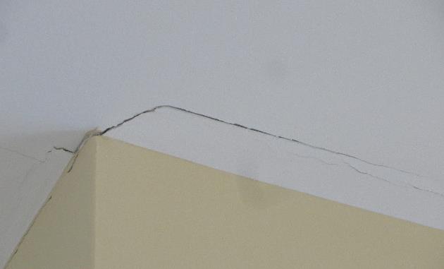
This type of movement goes by many different names that might sound familiar – truss arching, truss uplift, partition separation, or – to use the most formal name – ceiling-floor partition separation. All of these names describe the separation that develops between interior partition walls and ceiling finishes, which can cause gaps in the drywall to open in the winter and close in the summer. This movement is often considered to be a truss issue; however, it is not always the trusses that do the moving, but rather the walls or floors, or both, beneath the trusses.
This issue is also not limited to truss construction, but can also occur with other types of wood construction. The truss industry has information on this topic to help educate the market about the causes of ceiling-floor partition separation, best practices and construction techniques for minimizing the movement, and how to accommodate this movement in the structure to prevent drywall cracking.
For those who are interested in a very thorough and technical discussion of this issue and all of the factors that can contribute to it, there is a Technical Note available from the Truss Plate Institute (TPI) called Ceiling-Floor Partition Separation: What Is It and Why Is It Occurring? Although it was written several years ago (by the Small Homes Council-Building Research Council), the information remains relevant because the problem and its causes are the same now as they were then. The Technical Note discusses the potential causes of ceiling-floor partition separation, which may include one or more of the following: attic moisture (and the differential shrinkage and swelling of truss chords due to seasonal changes in moisture content), foundation settlement, expansive soils, excessive cumulative shrinkage of wood framing members and errors made during the construction process such as pulling the camber out of a truss to attach it to a partition. There is even an Appendix with a brief discussion of longitudinal shrinkage and an example calculation showing how much upward deflection results when a truss arches because of differential shrinkage.
For a condensed version, there is also a document available from the Structural Building Components Association (SBCA) called “Partition Separation Prevention and Solutions (How to Minimize Callbacks Due to Gypsum Cracking at the Wall/Ceiling Interface)”. This single-page document is particularly useful for educating the industry to take the appropriate preventive measures during construction, which help minimize problems later.
For example, the use of slotted roof truss clips – such as our STC (see below) – is one preventive measure, since these clips allow for vertical movement, but still provide lateral support at the top of the wall. DS drywall clips can be used in conjunction with the STC clips to secure the drywall to the wall. Then, to allow the drywall ceiling to “float,” the drywall is not fastened to the bottom chord within 16” from the wall. Taking these steps allows movement between the truss and the wall, without causing cracking in the drywall at the wall/ceiling interface.
It is important to note that, while foundation settlement may indicate a structural problem and can be prevented by proper design, truss arching resulting from the natural shrinking/swelling of wood does not indicate any structural problem and cannot be avoided in the design process.
Horizontal Movement of Scissor Trusses
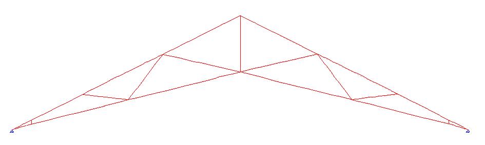
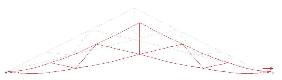
In the typical design of a scissor truss, a pin-type bearing is used at one end, and a roller-type bearing is used at the other end, which results in some amount of horizontal deflection at the roller bearing.
The bearing assumptions used in the design of a scissor truss are important not only to the truss, but they also have design implications for the building as well. Using a pin-type bearing at both ends of the truss has undoubtedly been a temptation to every truss technician at one time or another, when the same scissor truss that is failing the analysis suddenly works as soon as the bearings are switched from pin-roller to pin-pin. Unfortunately, that isn’t a valid option unless the walls are infinitely stiff (which they typically aren’t), or unless special measures are taken to resist the horizontal thrust that develops at the pinned reactions. In most cases, such measures won’t be taken which means with the exception of some rare cases, scissor trusses must be designed with pin-roller bearings.
The horizontal deflection that results when a scissor truss is designed with a roller bearing on one end prompts further questions and discussion. What happens when a scissor truss is rigidly secured to the walls of the building – how does that horizontal movement happen? How much horizontal movement is too much? Should the scissor truss be attached to the wall with a sliding (roller-like) connection?
First, a scissor truss that is rigidly secured to both walls will still experience horizontal movement due to the flexibility of the building’s construction in most residential and light commercial construction. How much horizontal movement is too much for the building? This is definitely a question that the Building Designer needs to answer based on his/her evaluation of the overall structure. However, there are a couple of resources that can provide some insight.
ANSI/TPI 1 has the following provision:
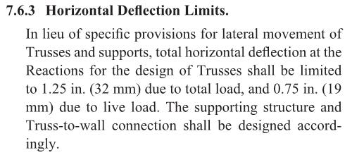
Per ANSI/TPI 1, a scissor truss can have up to 1.25″ of total horizontal deflection in the absence of stricter limits from the Building Designer. Scissor trusses may even be designed with more than this amount of horizontal deflection, along with a warning that special provisions for lateral movement may be required. It is important for the Building Designer to be aware of the calculated horizontal movement of the scissor truss, as reported on the truss design drawing, to ensure that it is an acceptable amount of horizontal movement for the supporting structure and/or to determine whether special provisions for the lateral movement need to be made.
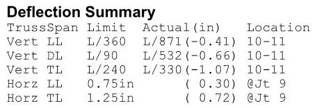
While 1.25″ of total horizontal deflection may seem like a lot of horizontal movement, these calculated horizontal deflections are considered to be conservative; many Designers agree that the predicted movement from the pin-roller bearing combination is greater than will actually occur in the constructed building. This is based on the fact that the design loads may be overstated and the contribution of the sheathing (and drywall if applicable) to resist the horizontal movement is not taken into account during the analysis of the truss.
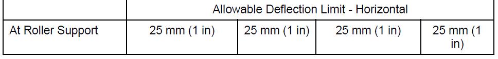
The National Building Code of Canada (NBC) references Section 5.4.4 of the 2009 Engineering Guide for Wood Frame Construction, which limits lateral movement at the top of each wall to h/500. This correlates to a total allowable horizontal movement of 3/8″ for 8ˈ walls. However, the Canadian truss design standard (TPIC-2014) permits trusses to have a horizontal deflection (at the roller support) of up to 1″. In this case, since the horizontal deflection of the truss exceeds the allowable horizontal deflection of the wall, a sliding connection needs to be used between the truss and the wall.
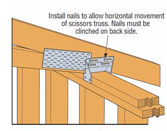
There are different opinions on the use of sliding connections, such as the slotted TC24 or TC26 connectors (see below), which allow for horizontal movement of the trusses without pushing out the wall, and also provide uplift resistance. The use of these clips also varies greatly by region. There are many places where these clips are used regularly and successfully. However, some Designers prefer to restrict the truss horizontal deflection and require the use of a positive connection between the scissor truss and the wall plate due to concerns regarding the transfer of lateral loads from the top of wall to the roof diaphragm. When TC connectors are used, they are often used on alternating ends of the trusses so that there is a positive connection along each wall at every other truss. Some Designers feel this approach minimizes the horizontal movement between the truss and the wall after the building is constructed and fully sheathed and braced.
There is not a single correct answer to address horizontal truss movement for every building. The amount of horizontal movement that is acceptable for the structure and whether or not a sliding connection should be used will depend on the building, the loading conditions, the designer’s experience and/or judgment, and, in some cases, the local building jurisdiction. What is more important than the decision to either restrict horizontal deflection or utilize sliding connectors like the TC24/TC26 (both have been successful) is that the bearing assumptions used in the design of the scissor truss are accounted for in the design of the building. The worst-case scenario is when a scissor truss is designed with a pin-pin bearing and installed in a building where absolutely no measures have been taken to supply the needed resistance to the calculated horizontal thrust.
What are your thoughts or experiences with either seasonal up-and-down movement or horizontal movement? Let us know in the comments below!

Truss Repair Information: The Never-Ending Search
Truss repair is one of the most frequently asked about truss topics. Not surprisingly, when we asked for suggested truss topics in a truss blog earlier this year, truss repair information made the list. Because the summer months bring about a peak in new construction – and plenty of truss repairs to go along with it – the beginning of June is the perfect time to visit this topic.
From trusses that get dropped or cut/drilled/notched at the jobsite, to homeowners who want to modify their existing trusses to add a skylight or create attic space to fire-damaged trusses, a multitude of scenarios fall under the broad topic of truss repair. Today’s post focuses on various references and resources that can provide some assistance. But first it helps to break down the broad “truss repair” topic into more manageable-sized categories.
New Construction vs. Recent Construction vs. Old Construction
By far, the easiest type of truss repair is new construction, when the trusses either haven’t been installed yet or are still in the process of being installed. Whether the repair is relatively simple (e.g. a broken web) or a little more complicated (e.g. the trusses need to be stubbed), the beauty of new truss construction is that the truss manufacturer – and truss Designer – can be contacted and help with the repair. The truss Designer can easily open up the truss designs in the truss design software, quickly evaluate the trusses for the appropriate field conditions and issue a repair.
A good reference related to truss repairs for new truss construction is the Building Component Safety Information (BCSI) booklet jointly produced by SBCA and TPI. Section B5 of the BCSI booklet, which is also available as a stand-alone summary sheet, covers Truss Damage, Jobsite Modifications & Installation Errors. This field-guide document describes the steps to take when a truss at the jobsite is damaged, altered or improperly installed, common repair techniques, and the information to provide to the truss manufacturer when a truss is damaged, which will assist in the repair process.
The next easiest truss type to repair is recent construction, where the trusses were constructed recently enough that: a) the truss plates are easy to identify, and b) the truss design drawings may even still be available. In these cases, design professionals other than the original truss Designer may be contacted to repair the trusses. For some types of repairs, the design professional can work off the truss design drawing to design the repair. Other times it might be necessary to model and analyze the truss using structural design software; alternatively, a truss manufacturer can be contacted to model the truss in their truss design software for a fee.
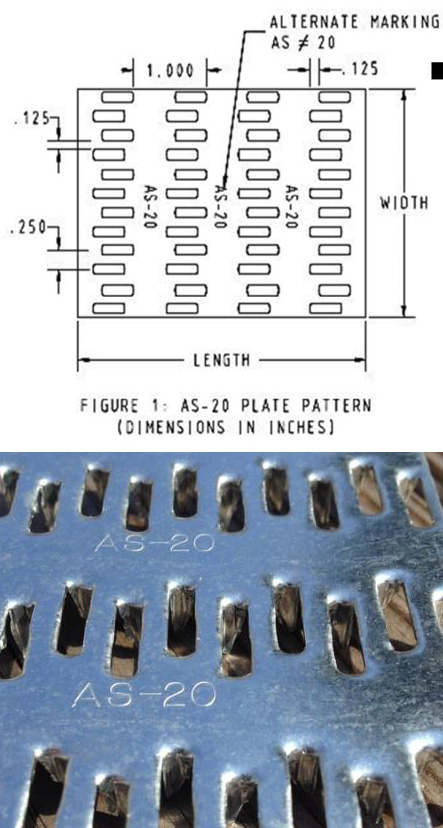
Often, the design professional wants to know the design values for the truss plates that were used to construct the truss. If there are truss design drawings available, they will indicate which truss plates were used in the design, and then the truss plate manufacturer can be contacted for more information. It is also easy to search for the truss plate code reports online (for instance, check icc-es.org). If no truss design drawing is available, there is still a way to identify the truss plates. Currently, there are only five major truss plate manufacturers in the United States, and they are listed on the Truss Plate Institute website. That makes identification of the truss plates used in recently constructed trusses easier because all of the current manufacturers’ plates will have markings that are described in their code reports. (Note that there are also a couple of truss manufacturers in the U.S. that manufacture their own truss plates.)
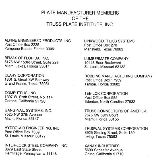
Finally, the most challenging type of trusses for truss repairs are those found in older buildings. Design professionals involved in these types of repair often aren’t sure where to start. Truss design drawings are often not available, and the act of trying to identify the truss plate manufacturer is challenging at best, unsuccessful at worst. As a point of reference, there were 14 truss plate manufacturers that were TPI members in 1987 (see image below), and only one of those companies is still in the current list of five companies. Therefore, the truss plates found in a truss built around 1987 will be difficult to identify. One option is to contact TPI and see if they can point you in the right direction.
Simple vs. Complex Repairs
Another way to break down truss repairs is to divide them into easy and challenging repairs. People often ask for “standard” truss repair details. Unfortunately, standard details only address the simplest types of repair; and those usually aren’t the types of repair that are asked about. Details simply cannot cover the wide range of truss configurations and every type of repair situation.
With the exception of simple repairs, most truss repairs rely heavily on the judgment and experience of the design professional doing the repair. And because there are not entire textbooks devoted to truss repair (that I am aware of, anyway), Designers must pull from a variety of resources, both to learn more about truss repair and to design the repair. For repairs using plywood or OSB gussets, the APA Panel Design Specification is a must-have reference. Some people prefer to use dimension lumber scabs for their repairs, whenever possible, simply because they are more familiar with dimension lumber (and the NDS) than they are with Plywood/OSB or the APA Panel Design Specification.
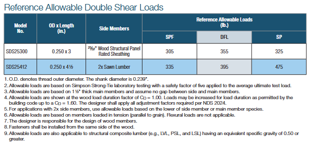
Next, the fasteners for the repair must be selected and the allowable loads determined. For nail design values, I am a big fan of the American Wood Council’s Connection Calculator, which provides allowable nail shear values for just about any combination of main and side members that you can think of, including OSB and plywood side members – particularly handy for truss repairs. For more complex repairs, and especially repairs involving higher forces, an excellent fastener choice is a structural wood screw such as our Strong-Drive® SDS or SDW screws. When I worked in the R&D department at Simpson Strong-Tie, a frequently asked question was whether we had double-shear values for our SDS screws. The questions always seemed to come from Designers who wanted them for truss repairs. Fortunately, we do have double-shear values for our SDS screws. You can find them on page 136 of our Fastening Systems Technical Guide.
The Strong-Drive SDW screw was developed after the SDS screw, and while there are currently no double-shear values for the SDW, it is still another good option for repairs.
Fire-Damaged Trusses and Truss Collapses
These situations are in a category by themselves because they go beyond even the most complex repairs involving a major modification to the truss. The biggest difference is that the latter case involves mostly known facts and perhaps some conservative assumptions, whereas damage due to fire or collapse includes many unknowns. Most of the truss Designers I have spoken to about truss damage due to fire or truss collapse often recommend replacement of the trusses rather than repair because it is usually too difficult to quantify the damage to the lumber and/or joints. In fires, there can be “hidden” damage due to the sustained high temperatures, while the truss appears to have no visible damage. Likewise, in a truss collapse, not only may there be too many breaks in the trusses involved in the collapse, but there may also be trusses that suffered severe stresses during the collapse and have damage that is not visible. To attempt a repair in either of these cases often requires an inspection at the jobsite, and the result may still end up being replacement of some or all of the trusses. Therefore, the cost of a full-blown inspection should be weighed against the cost of replacing the trusses.
The Structural Building Components Association website has a page with information pertaining to fire issues. It includes a couple of documents related to fire damage that are worth checking out.
Beyond the Blog: Where to Get More Truss Repair Information
The best bet for getting practical design information related to truss repairs is to keep an eye out for short courses, workshops or seminars. ASCE has hosted a Truss Repair Seminar (Evaluating Damage and Repairing Metal Plate Connected Wood Trusses) in the past and may very well offer something like it again. Virginia Tech recently hosted a short course on Advanced Design Topics in Wood Construction Engineering, which included a section on Wood Truss Repair Design Techniques.
What other references or resources for truss repair do you use? Are there any upcoming truss repair courses that you know of? Please let us know in the comments below!
From Structural Plans to Truss Designs – Collaborative Effort or Review Nightmare?
In an ideal world, a building is envisioned and a structural engineer begins the structural design. When the decision to use roof trusses is made, a component manufacturer is promptly involved in the design process. Using the loads and design parameters from the structural engineer, the trusses are designed and those designs are provided back to the engineer. The structural engineer then incorporates the truss designs into the building, transfers the loads through the structure and designs all the structural elements, bracing and connections necessary to provide a continuous load path down to the foundation. Finally, working from the complete and detailed plans, the contractor constructs the building flawlessly. Perfection!
But let’s get back to reality, where buildings are often designed and ground broken by the time the trusses are designed. The building Designer creates a roof framing plan to analyze and transfer the loads between the roof system and the rest of the building, and then designs the building (from the top plate down) accordingly. The component manufacturer (CM) eventually gets the plans and uses them to create a truss placement diagram and gather the truss design criteria. The CM then communicates the truss design parameters to the truss design engineer, who designs each of the individual trusses. The CM provides those truss designs and the truss placement diagram back to the building Designer. So far so good, right?
If every building were rectangular with a gable-style roof, this process would be fairly simple and hassle-free. But buildings are often more complicated than that. Roof systems can get very complex, so things don’t always go according to plan…such as when a wall that was intended to be non-load bearing gets used as a bearing location for the trusses; or when the CM moves a girder to a different location that works better for the trusses. Or maybe a truss can’t be designed for the entire span and an additional support is needed. In some cases, the CM may even flip the direction of the trusses completely because it results in a more efficient (lower-cost) truss package – that’s better for the building, right?
Changes during the design process can result in additional labor, material and cost. In today’s fast-tracked world, how can these expenses be avoided? Below are some suggestions from a truss Designer’s perspective.
Know each party’s design responsibilities
This may not seem like it has much to do with minimizing changes during the design process, but some problems arise from the fact that there is not always a common understanding of each party’s responsibilities. One misconception is that truss design engineers design an entire roof system, and they design the roof truss system to work within the framework of the building as set forth in the building structural plans. This is not true! Truss design engineers design single components, not systems. They do not even see the building Designer’s plans. It is the CM that receives the construction documents to obtain the truss design criteria and requirements. They in turn communicate the truss design parameters to the truss design engineer.
It is also important to understand the role the truss placement diagram plays in the overall process. This is a commonly misunderstood document, because many people think this is an engineered document prepared by the truss design engineer. Not only do truss design engineers not prepare these documents, they do not even review them. Instead, the CM creates the truss placement diagram after reviewing the construction documents. A truss placement diagram is only intended to identify the assumed location for each truss and serve as a truss installation aid. In fact, the truss industry intentionally changed the description of this document at one point from “truss placement plan” to “truss placement diagram” because the word “plan” has a connotation associated with engineering and design, and a truss placement diagram does not involve either of those.
Understanding how the truss industry operates and the responsibilities each party has in the design process will prevent incorrect assumptions from being made. If you find yourself saying, “I’m sure the truss design engineer will check this and take care of it…,” you probably need to think again.

The clearer the specifications, the better
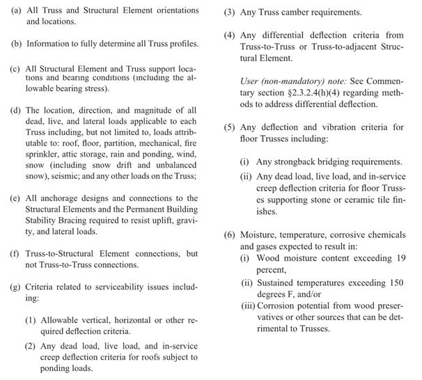
This may seem obvious, but do the construction documents contain all of the information necessary for the preparation of the truss design drawings? ANSI/TPI 1 specifies the required information in the construction documents (see text box below). Anything less than this information will mean assumptions need to be made during the creation of the truss placement diagram and the design of the trusses. The building Designer can also specify additional requirements to help ensure that the trusses they get are the trusses they want. In short, the more complete, accurate and detailed the construction documents are, the better the design process will be.
Review, review, review
It is the building Designer’s responsibility to review (and approve or reject) both the truss placement diagram and the individual truss design drawings for conformance with the overall building design. As mentioned earlier, the truss design engineer is solely responsible for the design of the individual trusses; they do not review the entire truss system and they do not check to see that the truss placement diagram meets the intent of the framing plan and specifications. Further, the component manufacturer relies on the completeness and accuracy of the information in the construction documents to create the truss placement diagram and to communicate the truss design requirements to the truss design engineer. Therefore, the success of the building’s construction depends on the building Designer’s thorough review of the truss submittal package.
Collaboration is key
Building Designers know what is best for the overall building; component manufacturers know what is best for the trusses. The best-case scenario is when the building gets the best of both. This requires collaboration during the planning stages, so that the strengths of both parties can be utilized to their maximum potential. A building Designer who finds out from the CM what the best setback distance is for a particular hip roof will not only minimize changes to the design downstream, but will also likely end up with a lower-cost building. On the other hand, a building Designer who provides some input into the actual truss designs, such as strategically placed webs in a string of trusses, will end up with a more efficient, permanent bracing plan that can even be included in the original construction documents.
Some may think the answer to this design process challenge is to let the building Designers design the trusses themselves; that all they need is the truss design software and they can design the trusses as part of their building design. But the truss industry knows that truss design software cannot replace the ingenuity and creativity of talented CMs who have a passion for what they do; just the same way that engineering software cannot ever replace an experienced engineer. That is why the truss industry continues to work hard to make it easier to collaborate, in lieu of providing truss design software to people outside of the component manufacturing industry. In this way, everyone’s skill sets can be fully utilized.
What do you think about this challenge? Let us know your thoughts in the comments below!