


Our “Quik” line of tools now has jobsite efficiency covered from subfloor to drywall to rafters. The Quik Stik overhead assembly fastening system is our most recent innovation in a line of fastening systems that also includes the Quik Drive® PRO250G3 subfloor system and the Quik Drive PRODW drywall system. It provides contractors with a versatile solution that makes fastening rafter and truss connections faster and easier than ever. Here are five ways the Quik Stik raises the bar on overhead fastening.
Continue Reading
Tag: trusses

A Tale of Two Houses: Design Loads for Metal Plate Connected Wood Trusses
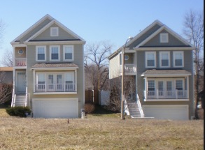
Take two trusses with identical profiles and environmental surroundings, and they should have the same design loads, right? Early in my career, I recall hearing a story about two identical buildings right next to each other that were designed for two different magnitudes of environmental loads. I remember wondering – how do the loads know which building is which?
There used to be a time when it was not uncommon for 5 substantially different wood truss designs to come from 5 different companies – all designing to the exact same spec. Whereas some differences are always to be expected (manufacturer-specific plate design values and proprietary analogues come to mind), the truss design disparities that used to exist from one company to the next were compounded by variations in something which really shouldn’t vary at all – the application of the specified loads to the truss. Differences in loading can occur whenever there is room for interpretation. In cases where the loading specs for fabricated wood trusses are not very detailed, there is a lot of room for interpretation. And when that happens, everyone knows how many different answers you get when you ask 5 different engineers!
Fortunately, the truss industry has come a long way in this area. In some cases, the codes and standards that govern the loading of structures have improved and helped the cause. But the truss industry also made a concerted effort to minimize these loading differences. Everyone agreed that a truss bid shouldn’t be won based on “less loading,” so they set out to change that. One of the best efforts in accomplishing this was the development of the SBCA Load Guide entitled “Guide to Good Practice for Specifying & Applying Loads to Structural Building Components.” Produced by the Structural Building Component Association (SBCA) in cooperation with the Truss Plate Institute (TPI), the Load Guide was developed with the stated goal of “helping everyone that uses it to more easily understand, define and specify all the loads that should be applied to the design of each structural building component” and “to help assure that all trusses will be designed using a consistent interpretation and application of the code.”
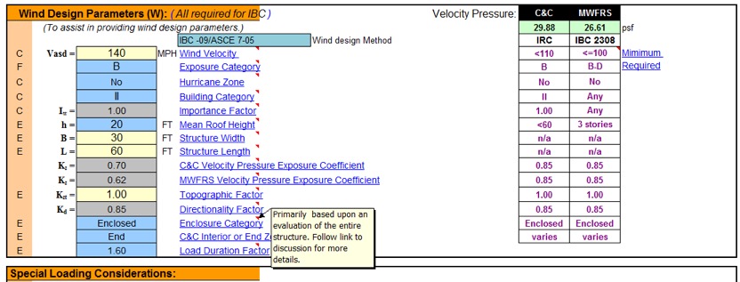
If you are an architect, engineer or a Building Code Official who deals with trusses and you don’t already have the current SBCA Load Guide, I strongly encourage you to check it out (free downloads are available from the SBCA website here.) When fielding questions about loading on trusses, I inevitably refer the inquiring party to the SBCA Load Guide not only for the answer to the question, but for future reference as well. The SBCA Load Guide isn’t just a handy reference to read, it also offers a spreadsheet tool that can be used to calculate loads as well as output the load calculation worksheets. The worksheets can be submitted with the construction documents for plan approval or submitted to the truss manufacturer to be used in the design process.
In addition to providing all of the code and standard loading provisions that apply to metal-plate-connected wood trusses, the SBCA Load Guide also presents the truss industry’s consensus positions and interpretations on provisions that are either unclear as to how they apply to trusses or that have resulted in loading inconsistencies in the past. With the many truss-specific examples and applications covered, it leaves very little room, if any, for further interpretation or question as to how the various code provisions should be applied to trusses.
Take wind loads, for example. Wind loading on trusses has been a heavily debated topic over the years, such as whether a truss should be designed for Components & Cladding (C&C), Main Wind Force Resisting System (MWFRS) or both. In fact, wind loading used to be one of the main sources of inconsistencies in truss designs from one company to another. The truss industry has since established a consensus position on this matter and the SBCA Load Guide presents it as follows:
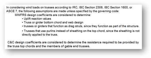
The SBCA Load Guide also pulls information from a variety of resources to help provide more insight into some of the code provisions. For example, in the wind loading section a graphic is reproduced from a Structural Engineers Association of Washington’s handbook (SEAW RSM-03) to clarify the effect of wind directionality on C&C wind pressures for gable/hip roofs, since this consideration is not made clear in ASCE 7.
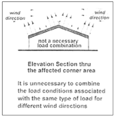
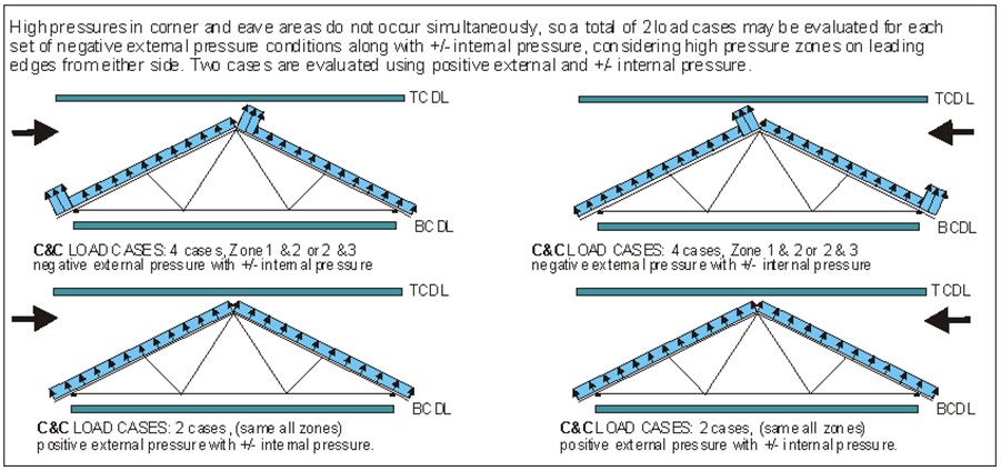
This clarification is further illustrated in the example wind loading diagrams, which show how wind pressures are evaluated when taking the directionality of the wind into account, i.e., by evaluating the pressures separately with the wind from the left and from the right.
Of course, the SBCA Load Guide is only a guide and is NOT intended to supersede a Building Designer’s design specification. As specified in ANSI/TPI 1, the Building Designer is responsible for providing all applicable design loads to be applied to the trusses:
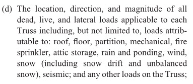
If you are an architect or engineer who specifies detailed loading schedules for truss systems, great! Your specifications may not need the SBCA Load Guide to ensure that the trusses are accurately loaded as intended in the design of the building. But the SBCA Load Guide still provides a lot of insight as to how the truss industry – and anyone who uses the Load Guide – applies various code provisions to trusses. It might even be an interesting study to see how your specified loads compare to the loading examples in the SBCA Load Guide.
For everyone else who isn’t well-versed in the application of code provisions to wood trusses, the SBCA Load Guide is an invaluable tool. Building Designers, building code officials, truss technicians and truss Designers can all benefit from the Load Guide. As stated in the SBCA Load Guide, one of the industry’s goals is to achieve a greater level of consensus among the largest audience possible on how to load trusses and other structural building components. The more people who read and use the SBCA Load Guide, the more consistency there will be in the interpretation and application of code provisions pertaining to wood trusses, which will help make projects run smoother and most importantly, improve building safety. At Simpson Strong-Tie, we are big fans of tools that work to do that.
If you’ve had experience using the SBCA Load Guide, we’d love to hear about it – please let us know in the comments below!

Simultaneous Loading on Hurricane Ties
“Structures are connections held together by members” (Hardy Cross)
I heard this quote recently during a presentation at the Midwest Wood Solutions Fair. I had to write it down for future reference because of course, all of us here at Simpson Strong-Tie are pretty passionate about connections. I figured it wouldn’t take too long before I’d find an opportunity to use it. So when I started to write this blog post about the proper selection of a truss-to-wall connection, I knew I had found my opportunity – how fitting this quote is!
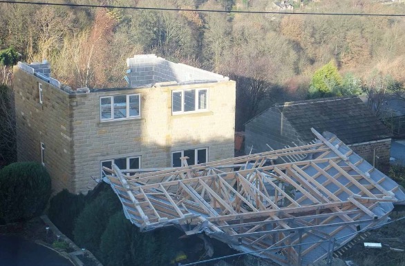
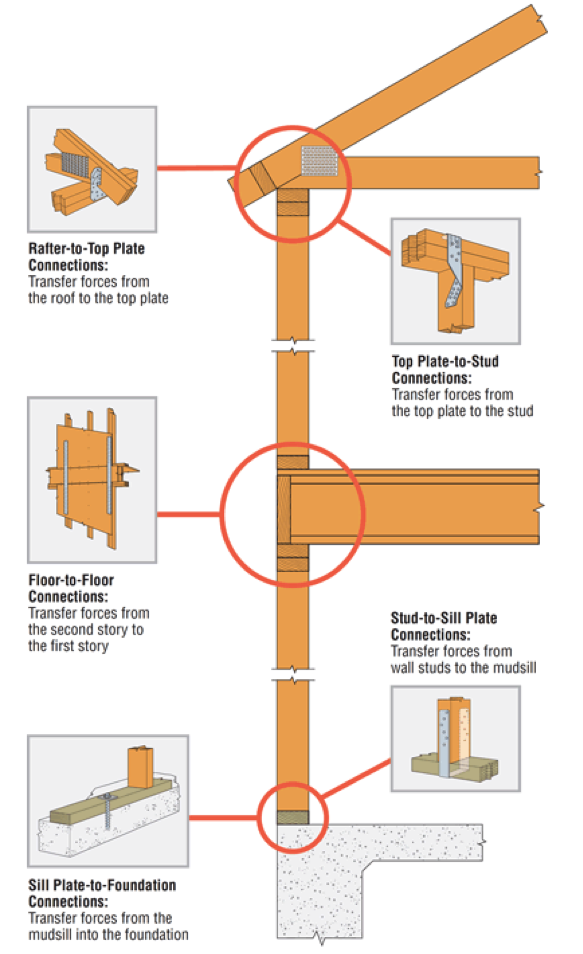
There are plenty of photos of damage wrought by past hurricanes to prove that the connection between the roof and the structure is a critical detail. In a previous blog post, I wrote about whose responsibility it is to specify a truss-to-wall connection (hint: it’s not the truss Designer’s). This blog post is going to focus on the proper specification of a truss-to-wall connection, the methods for evaluating those connections under combined loading and a little background on those methods (i.e., the fun stuff for engineers).
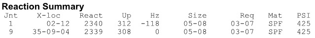
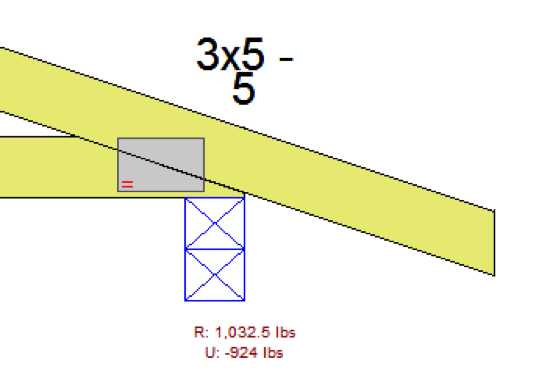
Take a quick look at a truss design drawing, and you will see a reaction summary that specifies the downward reaction, uplift and a horizontal reaction (if applicable) at each bearing location. Some people are tempted to look only at the uplift reaction, go to a catalog or web app, and find the lowest-cost hurricane tie with a capacity that meets or barely exceeds the uplift reaction.
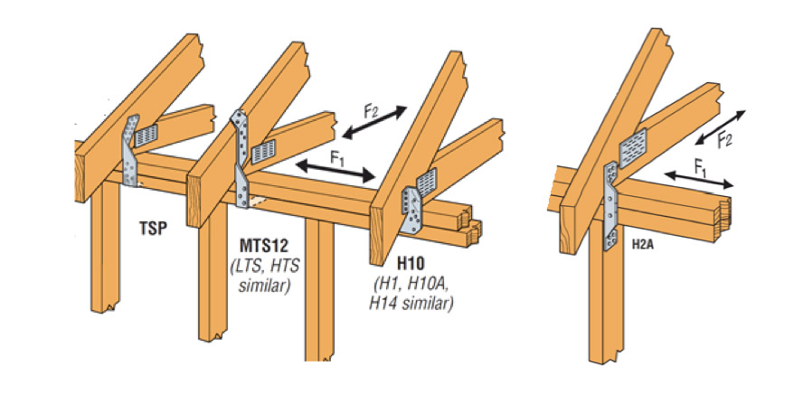
However, if uplift was the only loading that needed to be resisted by a hurricane tie, why would we publish all those F1 and F2 allowable loads in our catalog?

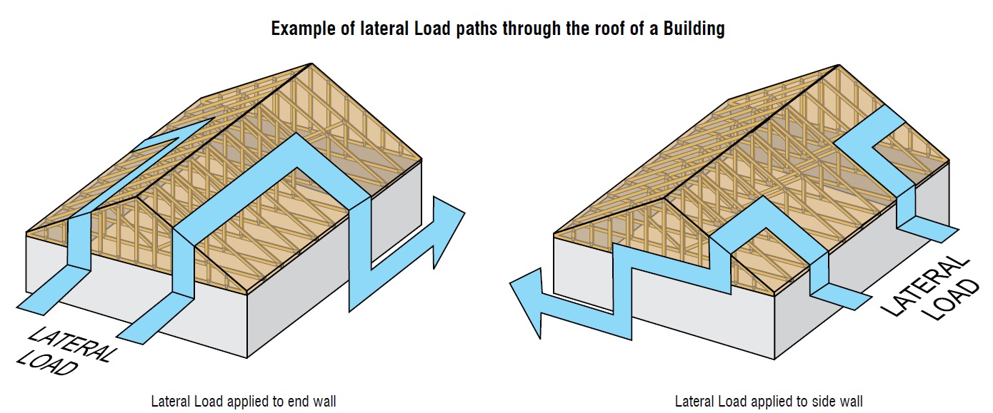
Of course, many of you know that those F1 and F2 allowable loads are used to resist the lateral loads acting on the end and side walls of the building, which are in addition to the uplift forces. Therefore, it is not adequate to select a hurricane tie based on uplift reactions alone.
Where does one get the lateral loads parallel and perpendicular to the plate which must be resisted by the truss-to-wall connection? Definitely not from the truss design drawing! Unless otherwise noted, the horizontal reaction on a truss design should not be confused with a lateral reaction due to the wind acting on the walls – it is simply a horizontal reaction due to the wind load (or a drag load) being applied to the truss profile. It is also important to note that any truss-to-wall connection specified on a truss design drawing was most likely selected based on the uplift reaction alone. There may even be a note that says the connection is for “uplift only” and does not consider lateral loads. In this case, unless additional consideration is made for the lateral loads, the use of that connector alone would be inadequate.
Say, for example, that the uplift and lateral/shear load requirements for a truss-to-wall connection are as follows:
Uplift = 795 lb.
Shear (parallel-to-wall) = 185 lb. (F1)
Lateral (perp-to-wall) = 135 lb. (F2)
Based on those demand loads, will an H10A work?
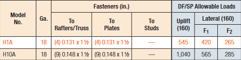
An initial look at the H10A’s allowable loads suggests it might be adequate. However, when these loads are entered into the Connector-Selector, no H10A solution is found.
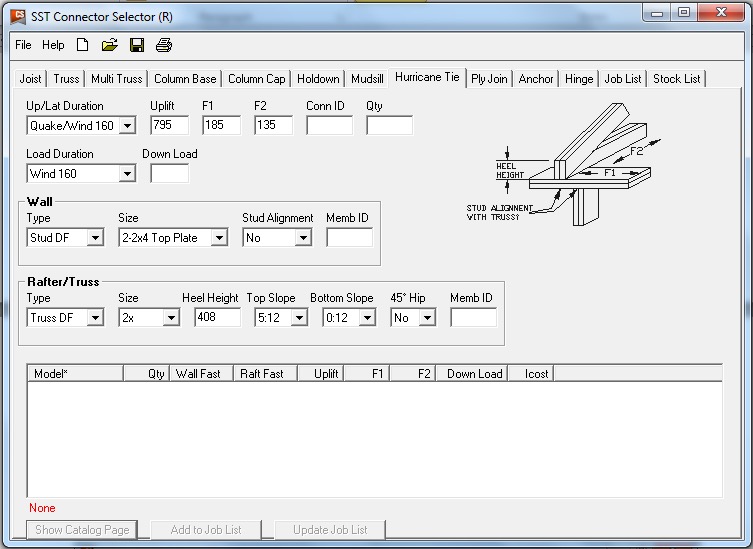
Why? Because Connector-Selector is evaluating the connector for simultaneous loading in more than one direction using a traditional linear interaction equation approach as specified in our catalog:
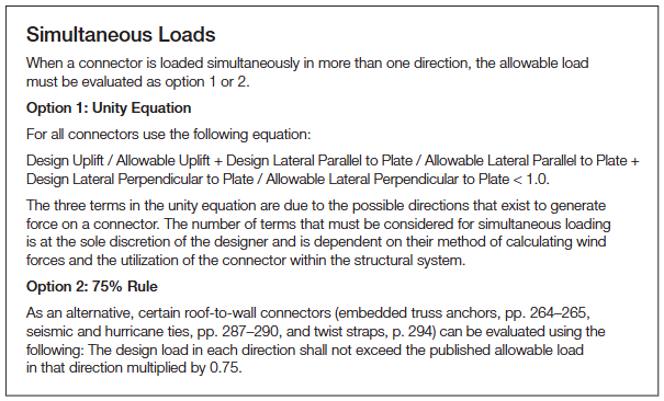
If the shear and lateral forces were to be resisted by another means, such that the H10A only had to resist the 795 lb. of uplift, then it would be an adequate connector for the job. For example, the F1 load might be resisted with blocking and RBC clips, and the F2 loads might be resisted with toe-nails that are used to attach the truss to the wall prior to the installation of the H10A connectors. However, if all three loads need to be resisted by the same connector, then the H10A is not adequate according to the linear interaction equation.

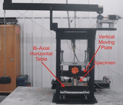
Some might question how valid this method of evaluation is – Is it necessary? Is it adequate? How do we know? And that is where the interesting information comes in. Several years ago, Simpson Strong-Tie partnered with Clemson University on an experimental study with the following primary objectives:
1. To verify the perceived notion that the capacity of the connector is reduced when loaded in more than one direction and that the linear interaction equation is conservative in acknowledging this combined load effect.
2. To propose an alternative, more efficient method if possible.
Three types of metal connectors were selected for this study – the H2.5A, H10, and the META20 strap – based on their different characteristics and ability to represent general classes of connectors. The connectors were subjected to uni-axial, bi-axial and tri-axial loads and the normalized capacities of the connectors were plotted along with different interaction/design surfaces.
These interaction plots were used to visualize and parameterize the combined load effect on the capacity of the connectors. The three different interaction plots that were examined were the traditional linear relationship, a quadratic interaction surface and a cuboid design space.
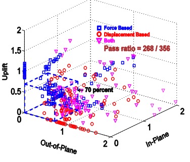
The results? Not only was the use of the linear interaction equation justified by this study, but a new, more efficient cuboid design surface was also identified. It provides twice the usable design space of the surface currently used for tri-axial loading and still provides for a safe design (and for the bi-axial case, it is even more conservative than the linear equation). This alternative method is given in our catalog as follows:

Now we can go back to the H10A and re-evaluate it using this alternative method:

As it turns out, the H10A does have adequate capacity to resist the simultaneous uplift, shear and lateral loads in this example. This just goes to show that the alternative method is definitely worth utilizing, whenever possible, especially when a connector fails the linear equation.
For more information about the study, see Evaluation of Three Typical Roof Framing-to-Top Plate/Concrete Simpson Strong-Tie Metal Connectors under Combined Loading.
What is your preferred method for resisting the combined shear, lateral and uplift forces acting on the truss-to-wall connections? Let us know in the comments below!

The New Truss Design Standard: Enter to Win A Copy of ANSI/TPI 1-2014 National Design Standard for Metal Plate Connected Wood Truss Construction
If you are like me, then you enjoy this time of the year. Instead of looking back and reviewing the events of the past year, this is the month for looking ahead at the year to come and what’s in store. So what is in store for 2015?
For the truss industry, there is a new truss design standard that was just released the last week of December. Still hot off the press, the ANSI/TPI 1-2014 standard is a revision to the 2007 edition and is referenced in the 2015 International Building Codes.
While the 2015 I-Codes might take some time for some municipalities to adopt, others are gearing up for adoption of the 2015 I-Codes as early as mid-2015. Either way, it is always good to know what is in the latest and greatest code-referenced design standards. So here’s a look at the new ANSI/TPI 1-2014 truss design standard:
First, here is a brief primer on the TPI 1 standard. The Truss Plate Institute (TPI) published the first truss design criteria in 1960. Many updates to these design criteria followed after that, and in 1995, TPI published its first ANSI-accredited truss design standard, ANSI/TPI 1-1995. Subsequent editions of this American National Standard have included ANSI/TPI 1-2002, ANSI/TPI 1-2007, and now ANSI/TPI 1-2014. All of the TPI standards, including archived copies going all the way back to TPI-60, are available from TPI (www.tpinst.org). Here is a link to the overview of non-editorial changes from ANSI/TPI 1-2007 to ANSI-TPI 1-2014.
While the 2007 edition included many significant revisions to the previous edition, the 2014 standard has relatively few substantive changes to the 2007 edition, which is good news for those who are still trying to catch up. Chapter 2 covers the design responsibilities involved in metal plate connected wood truss construction and looks different at first glance because it has been reorganized. However, the actual “Design Responsibilities” as they were defined in TPI 1-2007 have not changed.
In short, two separate sections in TPI 1-2007, which address design responsibilities in projects that require registered design professionals and projects that do not, have now been combined into one section. The “Truss Design Engineer” is simply referred to as the “Truss Designer” and the “Registered Design Professional for the Building” is simply the “Building Designer.” If the project requires registered design professionals, then the Truss Designer and Building Designer will be registered design professionals. Regardless of whether or not those two parties are registered design professionals, their responsibilities relating to the design and application of metal plate connected wood trusses are the same, so defining those responsibilities once within the TPI standard simplifies things and makes more sense.
Not new to the wood industry, but new to TPI 1-2014, are provisions for Load and Resistance Factor Design (LRFD). AF&PA incorporated LRFD provisions into the 2005 National Design Specification (NDS) for Wood Construction, and the TPI standard has followed suit, using the same basic approach as the NDS.
The section in TPI 1-2014 with the most changes is the section on deflection criteria. The deflection criteria have been revised in the last three editions of the TPI standard. Starting in TPI 1-2002, a requirement was added to consider creep in total deflection calculations. However, specific creep factors were not specified in the standard and were only presented in the Commentary. In the 2007 edition, creep factors were moved into the standard, and the total deflection calculation explicitly specified a component due to creep of no less than 50 or 100 percent of the initial deflection for long-term loads for dry and green (wet service) use, respectively. This was consistent with the 1.5 and 2.0 creep factors specified in the NDS for total deflection calculations for seasoned and unseasoned conditions.
Between the 2007 and 2014 editions, an inconsistency was discovered between the TPI 1 deflection criteria and the deflection limits in the U.S. model building codes. While the intent of the TPI standard was to present the same basic L/xxx deflection limits for Live Load and Total Load as the model building codes, it was discovered that the IBC deflection limits for “DL + LL” were actually intended to address only the creep portion of the dead load deflection plus the immediate live load deflection. So although long-term deflection including proper creep considerations can be an important consideration in the overall design of the building, it is not intended to be used to limit the design of a truss with respect to building-code established limits on vertical deflection.
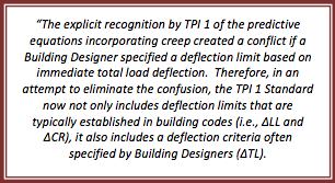
To resolve the issue of inconsistent methods used in the building industry to specify deflection limits, the 2014 edition now distinguishes between the following:
• “Deflection due to Live Load Plus Creep Component of Deflection due to Dead Load” for purposes of meeting the IBC deflection limits for DD + LL, which is defined as
ΔCR = Δ LL + (Kcr ‐1) x Δ DL
• “Long-Term Deflection”, which includes the full effect of creep but for which there are no explicit deflection limits specified in TPI
• “Deflection due to Total Load”, which is based on the full load (including both dead load and live load), but includes no explicit creep factors. The deflection due to total load has the same deflection limits as the IBC deflection limits for DD + LL, but this is not a mandatory check in TPI; it only applies to trusses if the Building Designer specifies that such a check due to total load be performed. Further, any consideration for creep in that calculation would also have to be specified by the Building Designer.
In recognition of the increased creep in trusses compared to solid sawn beams, the creep factors have been increased to 2.0 and 3.0 for dry and green (wet service) use, respectively. For purposes of deflection checks in accordance with the IBC, these factors reduce to 1.0 and 2.0, respectively, since the equation for “Deflection due to Live Load Plus Creep Component of Deflection due to Dead Load” uses KCR-1 rather than KCR as the factor on the immediate deflection due to dead load.
What does this all mean? For the majority of truss applications (e.g., dry-service), the effect of switching from TPI 1-2007 to TPI 1-2014 will be a change in creep factor from 1.5 to 1.0, unless additional requirements are specified by the Building Designer. Those additional requirements may include a limit on long-term deflection or a check for total load deflection (subject to the TPI deflection limits), including any considerations for creep.
A complete listing of the changes in TPI 1-2014 and more discussion about these changes are available in the TPI 1-2014 Commentary.
Now is your chance to win a copy of the ANSI/TPI 1-2014 standard for your own design library! Simply post a truss-related question, comment or idea for a future truss-related blog topic, and we will enter you into a drawing during the week of Jan 15-22. One winner will be picked at random. We look forward to hearing from you!

Truss-to-Truss and Truss-to-Everything Else Connections
One of the questions I am asked most frequently is “Who is responsible for the truss-to-(fill in the blank) connection? One such example is the truss-to-wall connection. To answer this question, it helps to recognize there are two types of connections: a truss-to-truss connection and a “truss-to-everything-else-except-a-truss” connection. The Truss Designer is responsible for the former, and the Building Designer is responsible for the latter. Pretty simple, right? So why all the questions?

Some people incorrectly assume the Truss Designer is responsible for connecting the truss to everything the truss touches. Then, when the Truss Designer doesn’t specify a connection to something the truss touches (such as a wall), it prompts the question, “Hey, who is responsible for that connection? I thought the Truss Designer was!” In other cases, the person asking the question is actually challenging the answer, such as “Shouldn’t the Truss Designer be specifying the truss-to-wall connection? Why don’t they?” And finally, the question may be prompted at times when the project doesn’t have a Project Engineer (aka the Building Designer), so the question becomes, “Now who is going to specify that connection? It must be the Truss Designer, right?”
But the Truss Designer isn’t responsible for the truss-to-wall connection – and here’s why. Unless the scope of work has been expanded by contract, the Truss Designer is responsible for designing an individual component. The truss gets designed for a given set of specified loads, environmental conditions, serviceability criteria and support locations, all which are specified by the person responsible for the overall building: the Building Designer. Once designed, the truss will have a maximum download reaction and uplift reaction (if applicable) at each support location. Is that enough information to specify a truss-to-wall connection? No, it is not. First, the Truss Designer may not know what the truss is even sitting on; he or she may only know that the bearing is SPF material and 3 ½” wide. Is it a single top plate or double top plate? Is there a stud below the truss that can be connected to, or is the stud offset? Or, is the truss sitting on a header spanning across a wide window?
Second, even if the Truss Designer had all of the information regarding the bearing conditions, there is another problem. The Truss Designer has the reactions resulting from the loads applied to the truss. What about the reaction at the top of the wall (perpendicular to the wall) resulting from the lateral loads applied to that wall? And the shear loads acting parallel to the wall as a result of lateral loads applied to the end wall? These loads also need to be resisted by the truss-to-wall connection (hence, the F1 and F2 allowable loads that are published for hurricane ties), so the Truss Designer cannot select an adequate truss-to-wall connection based on the truss reactions alone.
Finally, there’s one more scenario to consider. Say a Building Department requires that truss-to-wall connections must be specified by the Truss Designer on projects that have no Engineer of Record. It wants to ensure trusses are adequately secured to the walls, and the Truss Designer may seem best equipped to determine those connections (this has actually happened in some places). The Truss Designer can find out what exactly the truss is sitting on, and can even calculate some approximate reactions for the top of the wall to conservatively take into account during the selection of the connection. Problem solved? Not entirely. That takes care of the top of the wall, but the load doesn’t stop there. So requiring the Truss Designer to specify the truss-to-wall connection only transfers the problem to the bottom of the wall. Who is going to address those connections?
While most people don’t think of the Truss Designer as being the person responsible for the connections at the bottom of the wall, many do think the Truss Designer should be responsible for the connections at the top of the wall. But because someone – namely, the Building Designer – still needs to ensure that a continuous load path has been satisfied by the connections in the building, does it really help to increase the scope of work of the Truss Designer to specify the truss-to-wall connection?
Let us know your thoughts in the comments below.

Snow Loads vs. Top Chord Live Loads – A Historical Look at Snow Loading for Trusses
In my former life working as a consulting engineer, I reviewed many truss submittal packages. I remember during my reviews wondering how it was possible to get so much information on to an 8½ inch by 11 inch piece of paper. I also remember how a lot of what was being reported was difficult to understand without some help interpreting the information.
As many of you may know, Simpson Strong-Tie has ventured into the truss industry and we are now offering truss connector plates and software to component manufacturers around the country. So given my past experiences, I figure some of you might appreciate some insight into the engineering that goes on behind those truss submittal packages. So I have asked one of our great truss engineers, Kelly Sias, to put together some blog posts on the topic that we can share our knowledge with you. Kelly has worked in the truss industry for years and spent time as the Technical Director at the Truss Plate Institute. I am sure her blog posts are going to help all of us have a better appreciation for trusses.
Have you ever been involved in a discussion with someone on a project that ended with “but that’s the way we’ve always done it!”? I heard those words spoken by a contractor in my first engineering job when I tried explaining why his single stud would not work at a particular location. When he said something about his grandfather having always done it that way, I knew I could explain the calculations all day and it wouldn’t do much good.Continue Reading
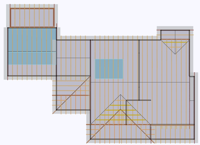
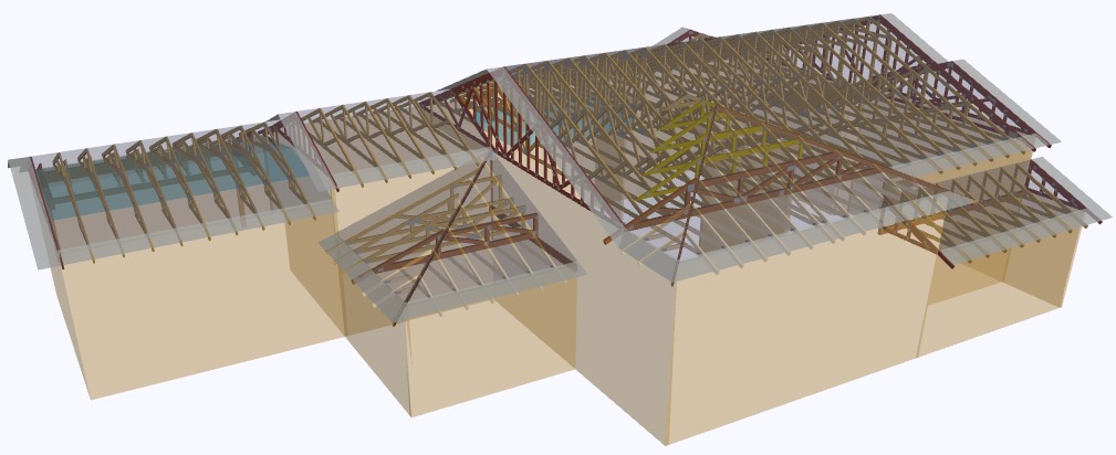
Plated Wood Truss Hip End Styles
For many, the first day of summer means it is time to cinch up your favorite hip-hugging bathing suit and enjoy the warm weather. For the truss industry, it’s time to keep those hip-hugging bathing suits in the closet and take advantage of the favorable weather months by bidding and building as many jobs as possible. During the bid and build frenzy, there will be several hip end jobs leaving truss yards across the country, but what exactly is a hip end and what are the different styles?
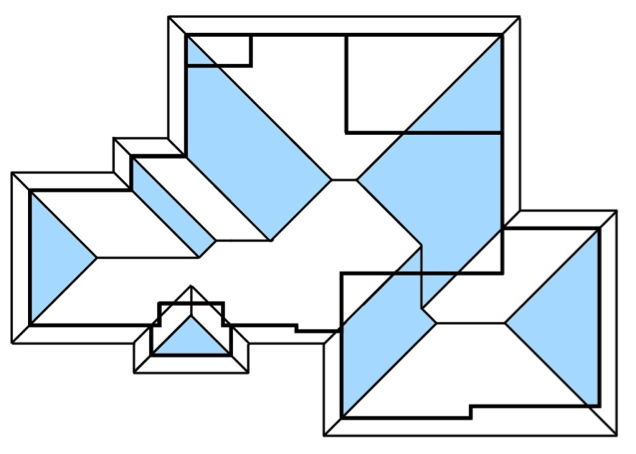
The Structural Building Components Association website (SBCA) defines a hip roof as a “Roof system in which the slope of the roof at the end walls of the building is perpendicular to the slope of the roof along the sides of the building.” While framing terms differ by region, most trussed hip end systems will include hip trusses, jack trusses (end and side) and a rafter or corner girder truss. Hip end style and setback (distance from side or end walls to the hip girder truss) may also vary by building design and region.
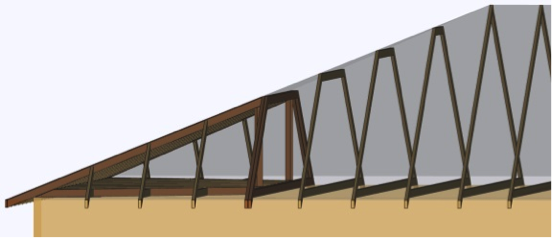
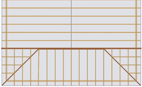
In the western part of the country, a California Hip system is typically seen in many trussed structures. In this hip system, the hip truss flat top chord is dropped by the plumb cut of the jack top chord at the roof pitch. By doing this, the top chords of the end jack trusses can pass over and bear on the dropped flat top chords. As the height of the hip end roof plane increases, the height of the flat top chord also increases, though the interval at which the flat top chord height increases may vary by building design and region.
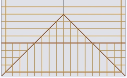
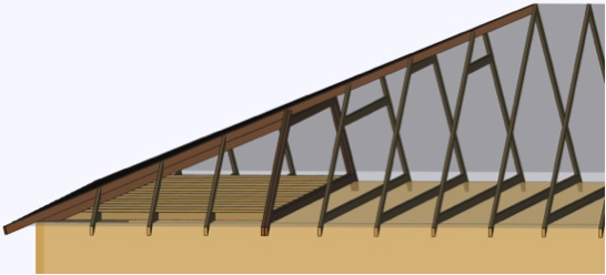
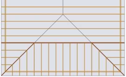
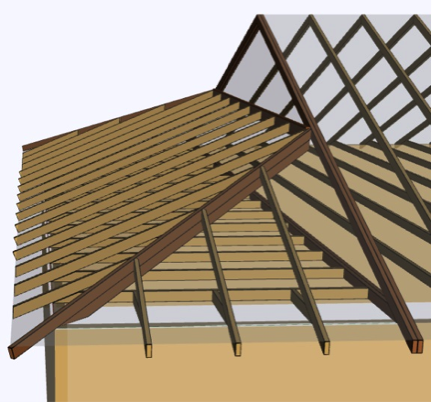
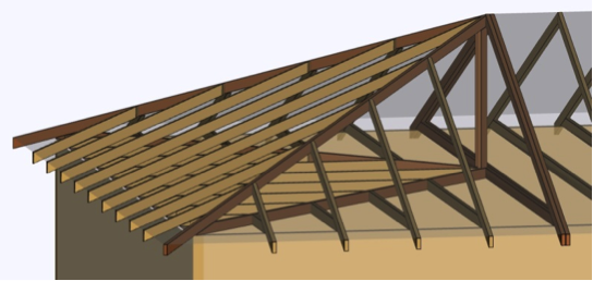
East of the Rocky Mountains, the California Hip is rare and a Step-Down Hip system is more popular. Differing from the California Hip, a Step-Down Hip system is one where every truss under the hip end plane decreases in height, or “steps down” from the apex until it reaches the hip girder, which is placed at a pre-determined setback.
Less regional and more situational depending on the building design, are the Lay-In Gable, Dutch and Terminal Hip systems. The Lay-In Gable Hip system is one with many regional names and shares similarities with the California and Step Hip systems. Like the Step Hip, every truss steps down moving from the apex to the setback. Like the California, every truss flat top chord has a drop. However, the flat top chord is dropped by the plumb cut of a 1.5” member at the roof pitch, as the gable frame lays flat.

In a Dutch Hip system, the hip end roof plane does not converge with the side planes to form an apex. Instead, the hip end plane pitches directly into the girder truss that is placed at a predetermined setback. Jack trusses then connect to the hip girder truss or to a ledger attached to the hip girder truss. This hip system is also referred to as a Dutch Gable.
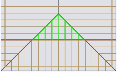
Assuming like roof pitches and heel heights, a Terminal Hip system is one where the hip girder truss setback is half of the main truss span or building width. If pitches and heel heights vary, the girder truss is placed at the apex of the three converging roof planes, which could be more or less than half of the main truss span or building width.

While these are some common hip end styles in the truss industry, there are definitely others. Each style has its own advantages and disadvantages, and a discussion of those will be the topic of a future post.
What other types of hip end styles are you familiar with? Let us know in the comment section below.

Plated Wood Truss Design Responsibilities
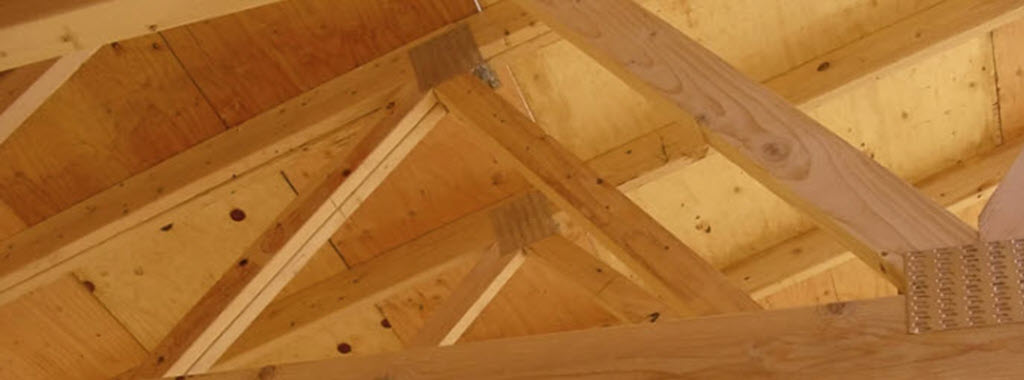
When the opportunity presents itself, glance up at the ceiling. Do you ever wonder who the responsible parties were for the design and construction of the roof above? If you’re involved in the truss industry, there is no doubt you have. If not, it never hurts to be in the know. Since we spend a significant portion of our life under a roof, it helps to know a few facts about what’s over our heads.
Roofs built from prefabricated wood trusses used in light-frame and residential construction will be the focus of this blog post.
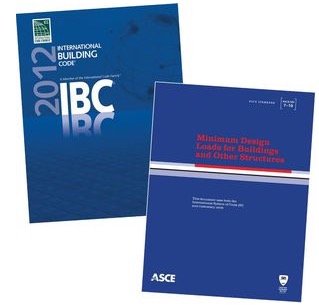
The current national design standard for metal plate connected wood truss construction is ANSI/TPI 1-2007, which is the referenced standard in the 2009 and 2012 IBC and IRC. So what are design responsibilities for wood trusses and why are they important? They are a series of responsibilities required by key parties for applications of trusses in the construction of a building. These key parties (Owner, Building Designer, Registered Design Professional, etc.) are important because each is required to produce pertinent information about the truss and truss system from its inception to erection and long in-service life.
As wood trusses have evolved, so have publications about their construction, quality and use. The first standard was published in 1960, with subsequent standards published periodically.
In 1995, the Truss Plate Institute (TPI) published ANSI/TPI 1-1995, which served as the first ANSI consensus-based national design standard for metal-plate connected wood truss construction. One of many new chapters established in ANSI/TPI 1-1995 was chapter 2, identifying design responsibilities. While early versions of ANSI/TPI 1 introduced design responsibilities, chapter 2 of ANSI/TPI -2007 has clarified and added areas of responsibility that are vital for today’s component industry. In addition, the 2007 edition defined responsibilities regarding temporary and permanent restraint and bracing, and special inspection requirements to long span trusses (any truss with a span of 60 feet or greater). These are just a few, yet critical additions to the standard.
Without clear definitions of responsibility, how would the industry know who specifies truss connections, or who provides bracing locations necessary to a roof assembly and its duration of service? Additionally, who determines if a project requires a truss submittal package, or the type of information it must provide? While these questions and more are answered in ANSI/TPI 1-2007, any provisions of the TPI 1 Design Responsibilities can be changed in the contract documents for a given project, so long as all parties are made aware of and agree to the revisions.
Ensuring all parties’ know and follow the design standard can help ensure a properly designed, manufactured and erected truss that will lead to a safe roof system. If you’re a component manufacturer, knowing what you’re responsible for and required to produce can get you out of a jam or better yet, help you avoid one altogether. Communication is key to the industry. The Commentary and Appendices of ANSI/TPI 1-2007 is available for web review: http://www.tpinst.org/technical-downloads
Do you know or want to know the answers to the above questions? Or perhaps think there are responsibilities that need to be clarified or added to future publications of ANSI/TPI 1? Let us know in the comment section below.