

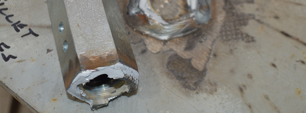
Continuous rod tiedowns are a common way to restrain shearwall overturning in light-frame structures. Anchoring the rod run in a steel beam can be challenging, however, because the holdown typically aligns with the beam’s web and thus cannot pass through the beam. Welding, on the other hand, can cause brittleness and fracture of the rod or coupler at the location of the weld, especially in high-strength steel rods and couplers. An effective alternative also using high-strength rods is provided by the Simpson Strong-Tie® ATS-SBC steel-beam connector, which comes with a steel plate whose flat edges can be fillet welded to the steel beam or embed plate without brittle failure. Scott Fischer, P.E., of Simpson Strong-Tie explains the results of our lab testing in the following post.
Continue Reading
Tag: light-frame construction
Anchor Testing for Light-Frame Construction
I started off doing a four-part series on how connectors, fasteners, concrete anchors and cold-formed steel products are tested and load rated. I realized that holdown testing and evaluation is quite a bit different than wood connector testing, so there was an additional post on holdowns. We have done several posts on concrete anchor testing (here and here), but I realize I never did a proper post about how we test and load rate concrete products per ICC-ES AC398 and AC399.
AC398 – Cast-in-place Cold-formed Steel Connectors in Concrete for Light-frame Construction and AC399 – Cast-in-place Proprietary Bolts in concrete for Light-frame Construction are two acceptance criteria related to cast-in-place concrete products.
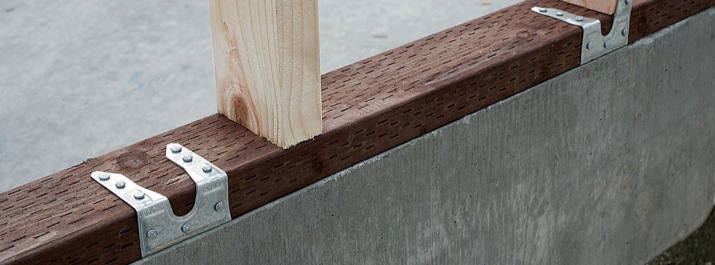
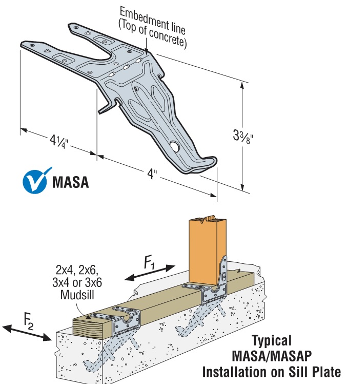
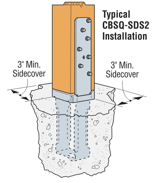
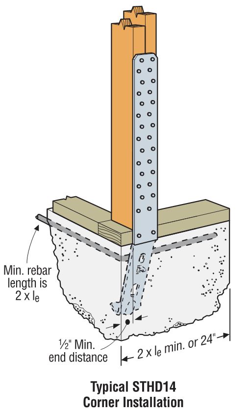
Cold-formed steel connectors embedded in concrete are not considered in ACI 318 Appendix D, so it was necessary to create criteria for evaluating those types of connectors. Some examples of products covered by AC398 are the MASA mudsill anchor, CBSQ post base, and the STHD holdown.
ACI 318 Appendix D addresses the design of cast-in-place anchors. However, the design methodology is limited to several standard bolt types.
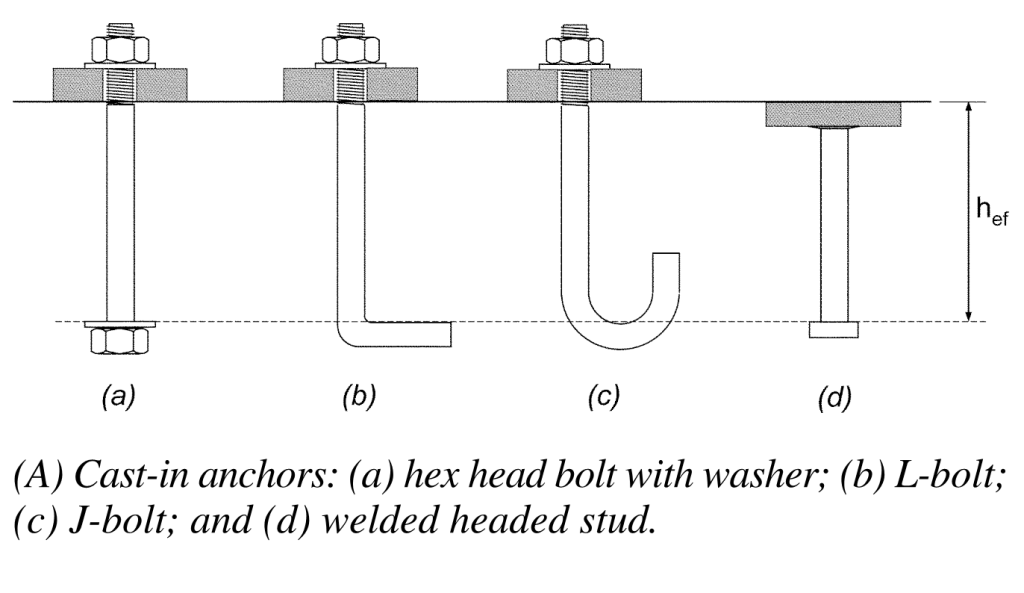
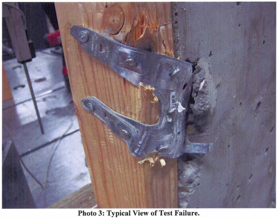
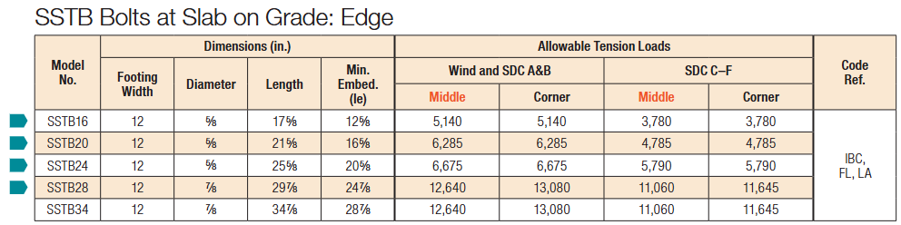
There are a number of anchor bolt products that have proprietary features that fall outside the scope of ACI 318, so AC399 fills in that gap by establishing test procedures to evaluate cast-in-place specialty anchors. Simpson Strong-Tie SB and SSTB anchor bolts are two families of anchors we have tested in accordance with AC399.
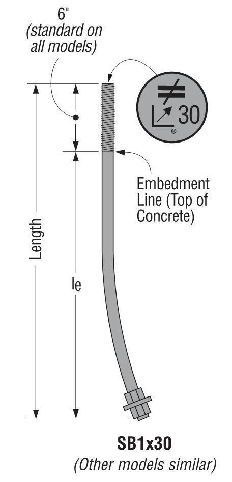
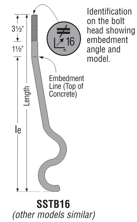
SB and SSTB anchors have a sweep geometry which increases the concrete cover at the anchored end of the bolt, allowing them to achieve higher loads with a 1¾” edge distance. The SSTB is anchored with a double bend, whereas the SB utilizes a plate washer and double nut.
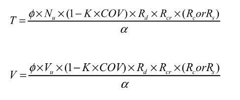
AC398 (concrete connectors) and AC399 (proprietary bolts) are similar in their test and evaluation methodology. AC398 addressing both tension and shear loads, whereas AC399 is limited to tension loads. Testing requires a minimum of 5 test specimens. These are the allowable load equations for AC398 and AC399:
For comparison, here is the standard AC13 allowable load equation for joist hangers:
Allowable Load = Lowest Ultimate / 3
Without getting into Greek letter overload, what are these terms doing?
Nu (or Vu) is the average maximum tested load. Calculating averages is something I actually remember from statistics class. Everything else I have to look up when we do these calculations.
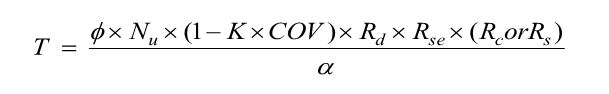
(1 – K x COV) uses K as a statistical one-sided tolerance factor used to establish the 5 percent fractile value with 90% confidence. This term is to ensure that 95% of the actual tested strengths will exceed the 5% fractile value with 90% confidence. COV is the coefficient of variation, which is a measure of how variable your test results are. For the same average ultimate load, a higher COV will result in a lower allowable load.
The K value is 3.4 for the minimum required 5 tests, and it reduces as you run more tests. As K decreases, the allowable load increases. In practice, we usually run 7 to 10 tests for each installation we are evaluating.
Rd is seismic reduction factor, 1.0 for seismic design category A or B, and 0.75 for all others. This is similar to what you would do in an Appendix D anchor calculation, where anchor capacities in higher seismic regions are reduced by 0.75.
Rs and Rc are reduction factors to account for the tested steel or concrete strength being higher than specified. There are some differences in how the two acceptance criteria apply these factors, which aren’t critical to this discussion. Φ is a strength reduction factor, which varies by failure mode and construction details. Brittle steel failure, ductile steel failure, concrete failure and the presence of supplemental reinforcement.
The α factor is used to convert LRFD values to ASD values. So α = 1.0 for LRFD and α = 1.4 for seismic and 1.6 for wind. Both criteria also allow you to calculate alpha based on a weighted average of your controlling load combinations. This has never made a lot of sense to me in practice. If you are going to work through the LRFD equations to get a different alpha value, you might as well do LRFD design.
Rse is a reduction factor for cyclic loading, which is applied to proprietary anchor bolts covered under AC399, such as the SSTB or SB anchors. A comparison of static load and cyclic load is required for qualification in Seismic Design Category C through F. Unlike the cracked reduction factor, manufacturers cannot take a default reduction if they want recognition for high seismic.
Due to the differences in AC398 and AC399 products, the load tables are a little different. AC398 products end up with 4 different loads – wind cracked, wind uncracked, seismic cracked and seismic uncracked.

AC399 products are a little simpler, having just wind and seismic values to deal with.
What are your thoughts? Let us know in the comments below.

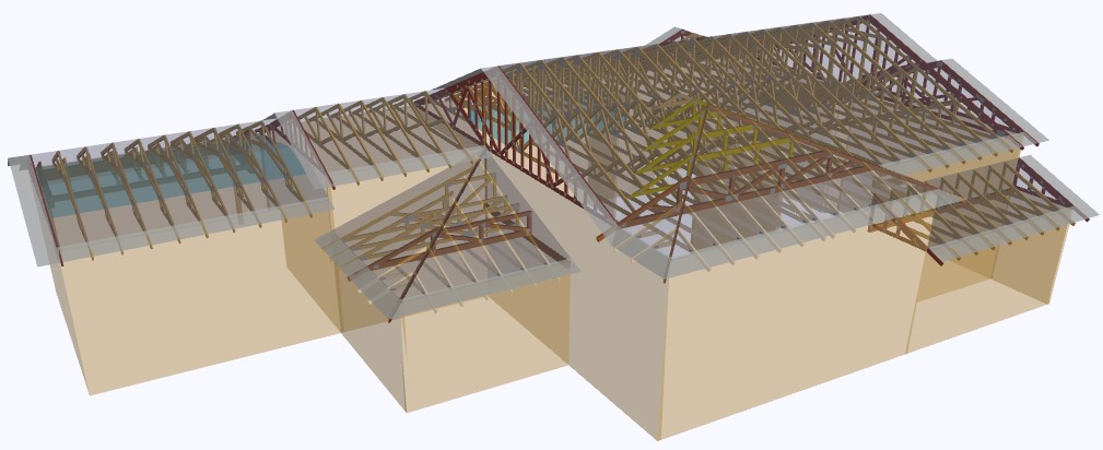
Plated Wood Truss Design Responsibilities
When the opportunity presents itself, glance up at the ceiling. Do you ever wonder who the responsible parties were for the design and construction of the roof above? If you’re involved in the truss industry, there is no doubt you have. If not, it never hurts to be in the know. Since we spend a significant portion of our life under a roof, it helps to know a few facts about what’s over our heads.
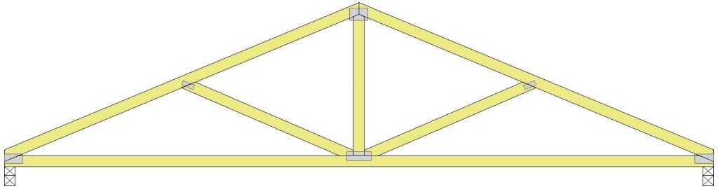
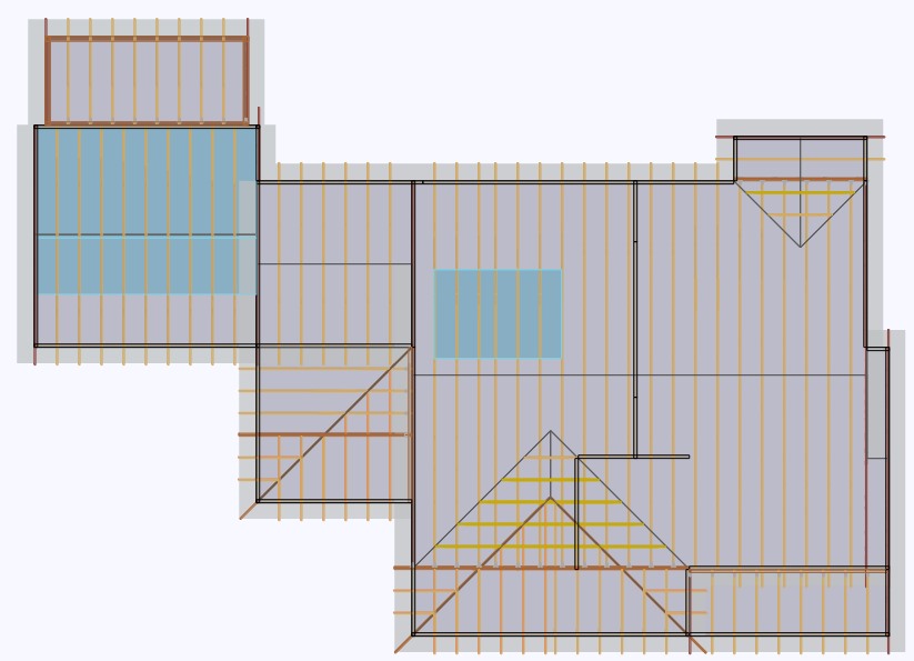
Roofs built from prefabricated wood trusses used in light-frame and residential construction will be the focus of this blog post.
The current national design standard for metal plate connected wood truss construction is ANSI/TPI 1-2007, which is the referenced standard in the 2009 and 2012 IBC and IRC. So what are design responsibilities for wood trusses and why are they important? They are a series of responsibilities required by key parties for applications of trusses in the construction of a building. These key parties (Owner, Building Designer, Registered Design Professional, etc.) are important because each is required to produce pertinent information about the truss and truss system from its inception to erection and long in-service life.
As wood trusses have evolved, so have publications about their construction, quality and use. The first standard was published in 1960, with subsequent standards published periodically.
In 1995, the Truss Plate Institute (TPI) published ANSI/TPI 1-1995, which served as the first ANSI consensus-based national design standard for metal-plate connected wood truss construction. One of many new chapters established in ANSI/TPI 1-1995 was chapter 2, identifying design responsibilities. While early versions of ANSI/TPI 1 introduced design responsibilities, chapter 2 of ANSI/TPI -2007 has clarified and added areas of responsibility that are vital for today’s component industry. In addition, the 2007 edition defined responsibilities regarding temporary and permanent restraint and bracing, and special inspection requirements to long span trusses (any truss with a span of 60 feet or greater). These are just a few, yet critical additions to the standard.
Without clear definitions of responsibility, how would the industry know who specifies truss connections, or who provides bracing locations necessary to a roof assembly and its duration of service? Additionally, who determines if a project requires a truss submittal package, or the type of information it must provide? While these questions and more are answered in ANSI/TPI 1-2007, any provisions of the TPI 1 Design Responsibilities can be changed in the contract documents for a given project, so long as all parties are made aware of and agree to the revisions.
Ensuring all parties’ know and follow the design standard can help ensure a properly designed, manufactured and erected truss that will lead to a safe roof system. If you’re a component manufacturer, knowing what you’re responsible for and required to produce can get you out of a jam or better yet, help you avoid one altogether. Communication is key to the industry. The Commentary and Appendices of ANSI/TPI 1-2007 is available for web review: http://www.tpinst.org/technical-downloads
Do you know or want to know the answers to the above questions? Or perhaps think there are responsibilities that need to be clarified or added to future publications of ANSI/TPI 1? Let us know in the comment section below.

Wide Flange Beams in Light Frame Construction
How did that beam get so big? This is what I had to ask myself when I finished sizing and detailing a steel beam that was supposed to fit within the floor joist depth for a flush ceiling. We were removing an unreinforced masonry bearing wall and installing a new wide flange beam to support the existing floor joists as part of a seismic retrofit and remodel. Since the floor joists spliced over the existing bearing wall, it would have been much easier to simply install a new beam below the joists.
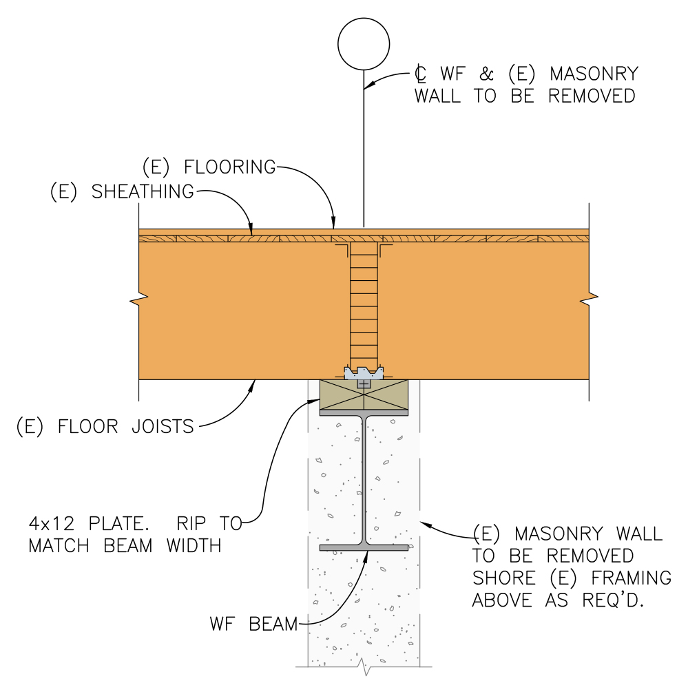
The architect did not want the beam installed below the framing, as it would protrude too much. Steel design offers multiple wide flange sections that will work for a given loading. For this particular design, I could use a W24x55, a W16x67 or a W14x90. Each has about the same strength (section modulus, Sxx) and stiffness (moment of inertia, Ixx). Without constraints, you would select the lightest section that works. Space limitations that require a shallower beam result in increased beam weight (and cost).
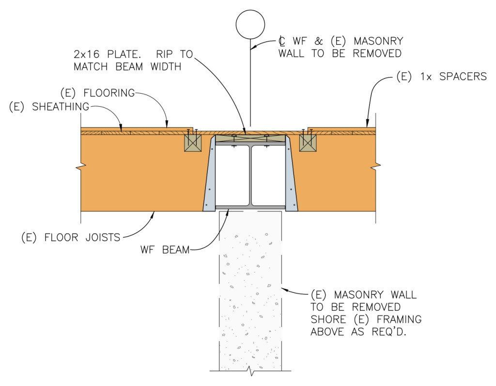
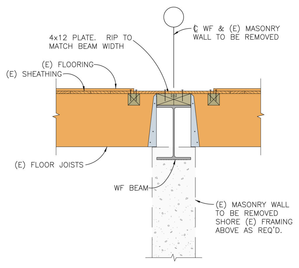
I proposed two solutions for installing the beam in the floor space and hanging the joists off a nailer. One option allowed the steel beam to extend below the floor joists, while the other used a heavier, shallower beam to fit within the space. The owner wanted a flat ceiling and did not mind the added cost for the beam, which weighed about 60% more than the optimum beam size.
Regardless of space constraints for the design of a steel beam, structural engineers need to specify an appropriate hanger for connecting to the steel beam. Simpson Strong-Tie has many suitable top flange hangers. Most common are hangers that are attached to a wood nailer. Many top flange hangers may also be welded to the beam. Not every nailer solution is rated for uplift, so choose a hanger that meets your requirements. Uplift for welded hangers is addressed in a Simpson Strong-Tie® technical bulletin, T-C-WELDUPLFT2.
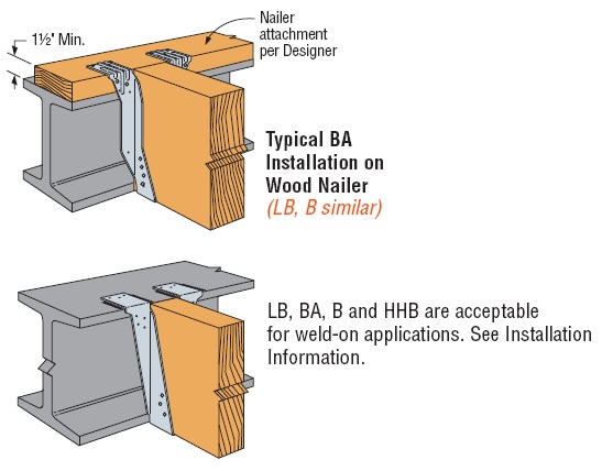
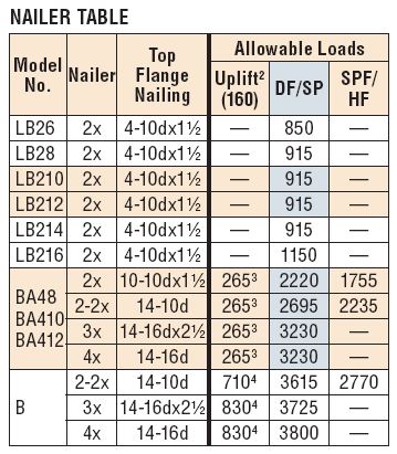
Installers may also wish to connect the hangers using powder-actuated fasteners in lieu of welding. Allowable loads for several of our top flange hangers are addressed in current catalog.
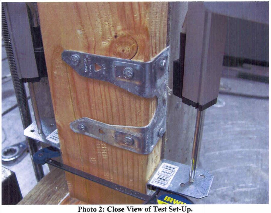
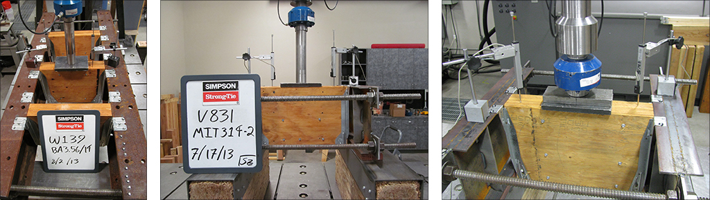
Of course, as with all of our hanger loads, we created those loads by running a lot of tests.
What are your thoughts on beam selection and installation? Let us know in the comments below.