Strong-Wall Bracing Selector: Bridging the Gap between Engineered Design and Prescriptive Construction

Asking a structural engineer to design wall bracing under the IRC® can be like asking a French pastry chef to bake a cake using Betty Crocker’s Cookbook. The temptation is to toss out the prescriptive IRC recipe and design the house using ASCE 7 loads and the AWC SDPWS shear wall provisions per the IBC®. But if only a portion of the house needs to be engineered, there may be an easier option.

The prescriptive IRC states an IBC engineered design “is permitted for all buildings and structures and parts thereof” but the design must be “compatible with the performance of the conventional framed system.” But how exactly does an IRC braced wall panel perform? The code doesn’t come right out and tell us, but there are two bracing methods that are essentially shear walls masquerading as braced wall panels: Method ABW and Method BV-WSP. Backing into their allowable loads gives us the key to determining equivalence and eliminates the need to develop lateral forces.

But before you can bust out the slide rule and start crunching numbers, you need to figure out how much bracing the prescriptive code requires. We developed our Wall-Bracing-Length Calculator in 2010 to help designers do just that. And last month, we launched our Strong-Wall® Bracing Selector tool to make it easier to specify equivalent solutions for tricky situations.

Strong-Wall Bracing Selector
Wall-Bracing-Length Calculator

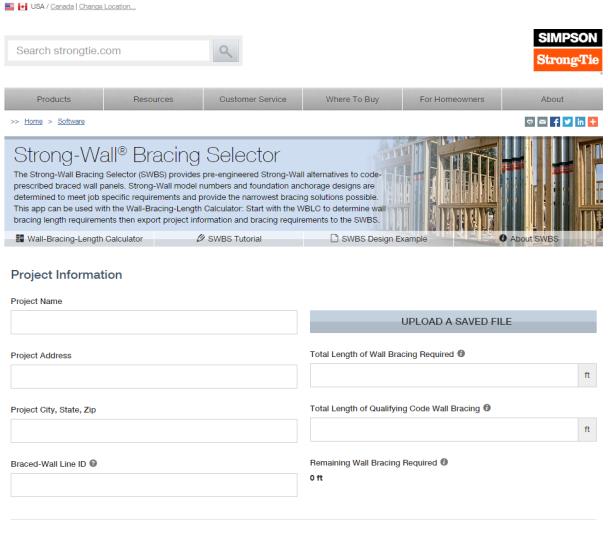
You can export the required lengths (and project information) from the Wall-Bracing-Length Calculator directly into the Strong-Wall Bracing Selector or you can manually enter in the required lengths. The selector app will provide a list of Strong-Wall panels that have an equivalent length, evaluate their anchorage loads and return a list of pre-engineered anchor solutions for a variety of foundation types.

If you’re familiar with our Strong-Wall Prescriptive Design Guide (T-SWPDG10), the selector automates this 84-page document in just a few steps. One big upgrade is the ability to select a solution to meet the exact amount of bracing that is required. If you needed 2.8-ft. of wall bracing, you have to round up to the tabulated 4-ft. solutions if you are using the guide, but now you can select a wall solution that is equivalent to 2.8-ft., which might mean a smaller wall width or better anchor options. You also have the ability to save the selector file for later modifications, create a PDF of the job-specific output, or email the PDF directly from the program.

Strong-Wall Prescriptive Design Guide

So next time you get asked to “design” some wall bracing, see if our Wall-Bracing-Length Calculator and Strong-Wall Bracing Selector might save you some time. There is a tutorial and a design example on the Bracing Selector web page, but it’s very easy to use so you may just want to dive right in. I should also point out that the Strong-Wall SB panels have not yet been implemented into the program, but bracing information for them is available on strongtie.com in posted letters for wind (L-L-SWSBWBRCE14), seismic (L-L-SWSBSBRCE14), and seismic with masonry veneer (L-L-SWSBVBRCE14).

Let us know what you think of this new tool in the comments below.


2015 IRC Adds New Options for Deck Construction

Early this summer a package arrived at my office that I knew right away was either a copy of a new building code or design standard. Some codes or standards are more exciting than others to open up and see what’s new and different. As it turns out, this package was the just-published 2015 International Residential Code (IRC). With my interest in wood decks, I have to admit that this was new information that I was happy to see.

Why? Similar to my blog post in May mentioning the limited design resources currently available to engineers, the IRC itself is also a work in progress when it comes to the prescriptive details included for decks. Performance requirements for the framing and guards has always been included in Chapter 3, but it wasn’t until the 2009 and 2012 editions that prescriptive information for attaching a deck ledger to a wood band joist with lag screws or bolts, and a detail for transferring lateral loads to a support structure, were included. Key improvements for the 2015 IRC include provisions for composite materials, clarification of the prescriptive ledger information, and prescriptive information for decking, joist and beam allowable spans, post heights and foundations.

Lateral load connections at the support structure were a significant topic during the development of the 2015 IRC. The permitted method already in the code involves constructing the Figure 507.2.3(1) detail with 1,500 pound hold-downs, in two or more locations per deck. The detail transfers the lateral load by bypassing the joist hanger and ledger connections, and ultimately transfers it into the floor diaphragm of the support structure. The concentrated nailing on the floor joist and the need to have access from below to the install the hold-down can cause undesirable complications for builders with existing conditions. A number of common conditions also differ significantly from the detail, such as the floor joists running parallel to the deck ledger and alternate floor joist types, including i-joists or trusses. In response to frequently-asked-questions from the industry, our technical bulletin T-DECKLATLOAD provides commentary to consider for these situations. The technical bulletin also offers an alternate floor joist-to-sheathing connection that may save the builder from removing a finished floor in an existing condition or from adding additional sheathing nailing from above.

2015 International Residential Code
Figure: 2015 International Residential Code; International Code Council

In order to provide greater flexibility, a second option is now included in the 2015 IRC: constructing Figure R507.2.3(2) with 750 pound hold-downs in four locations per deck. This detail also transfers the lateral load in bypassing the joist hanger and ledger connections, but transfers the load to the wall plates, studs, or wall header by means of a screw anchoring the hold-down. In some cases, builders will hope this detail can save removing interior portions of an existing structure, but close attention will be required in terms of the deck joist elevation with respect to components of the wall and ensuring that hold-down anchor has proper penetration into the wall framing.

Figure: 2015 International Residential Code; International Code Council

There are still a number of scenarios where a residential deck builder may need or want to consider hiring a structural engineer. Prescriptive details for guards and stairs are still not included in the code, as well as lateral considerations such as the deck diaphragm or the stability of a freestanding deck. Alternate loading conditions, such as the future presence of a hot tub, are also outside the scope of the current code. The allowance for alternative means and methods permitted by Chapter 3 of the 2015 IRC, is also something to keep in mind when the prescriptive options do not fit well with the project conditions. For example, the IRC ledger fastening table applies for connections to a band joist only and not to wall studs or other members of the adjacent support structure.

Have you been involved with any residential deck projects?  Let us know in the comments section below.

New Holdown Requirements for the IRC® and IBC® Portal Frame Bracing Method

The IRC® contains several different narrow bracing methods that are made up of portal frames. One method that is useful if you are using intermittent wall bracing is the Method PFH Portal Frame with Holdowns. This method relies on low-deflection holdown anchorage at the bottom, and substantial nailing at the overlap of the sheathing and the header at the top to prevent overturning of the narrow panel. An identical method for use as wall bracing is in the Conventional Construction section in Chapter 23 of the IBC®. These portal frames were first included in the 2006 IBC and IRC.

Method PFH- Portal Fram With Holdowns

The method was originally tested with straps clamped to a steel test bed to simulate the embedded holdown straps. The straps were nailed to the wood with enough nails to mimic a 4,200 lb. strap anchor. The original test report is APA T2002-70. At that time, the Simpson Strong-Tie® STHD14 had a published allowable load in excess of 4,200 lbs. based on then-current Acceptance Criteria, so hardware was available to construct this frame throughout the country. However, in 2008, ICC Evaluation Service developed a new acceptance criteria for embedded connectors, AC398, Acceptance Criteria for Cast-in-place Cold-formed Steel Connectors in Concrete for Light-frame Construction. This was in response to the changes in ACI 318 for anchors in concrete. When re-tested and evaluated using the new Acceptance Criteria, the allowable load for STHD14 was reduced below 4,200 lbs. for use in buildings designed for Seismic Design Categories C through F.   The same thing happened to other manufacturers’ embedded holdown allowable loads. That made it impossible to properly construct this bracing method in those areas. In response to this, Simpson Strong-Tie worked with APA, the Engineered Wood Association, to design a new test that would determine if a lower capacity holdown could be used with this portal frame method.  APA performed the testing at their Tacoma, Washington testing lab. Since the initial testing of the portal frames with the 4,200 lb. holdown was performed using the outdated SEAOSC protocol with an older testing rig that used a stiff beam above the wall, both the old tests with a simulated 4,200 lb. holdown and new tests with a simulated 3,500 lb. holdown were rerun in accordance with the current ASTM E2126 test method using the CUREe protocol. The test was published as Test Report T2012L-24. The tests showed little to no effect of reducing the holdown from 4,200 lbs. to 3,500 lbs. allowable load. Here is one of the graphs of the backbone curves comparing the two assemblies for a 16-inch wide, 10-foot tall portal frame.

Comparison graph of two assemblies for a 16-inch wide, 10-foot tall portal frame.

With the testing complete, APA prepared and submitted code changes to both the 2012 International Building Code® and 2012 International Residential Code®. The IBC proposal is S291-12, and can be found on page 605 of the 2012 Proposed Changes to the International Building Code – Structural. The IRC proposal is RB311-13, and can be found on page 613 of the 2013 Proposed Changes to the International Residential Code-Building. With support from Simpson Strong-Tie, both of the proposals were approved. So in the 2015 IRC, bracing method PFH will require an embedded strap-type holdown with a minimum capacity of 3,500 lbs. instead of 4,200 lbs. The same will hold true for the Alternate Braced Wall Panel Adjacent to a Door or Window Opening bracing method in the 2015 IBC. APA also re-tested the portal frames with only two sill plates instead of three. This will allow the use of a 5/8” by 8” Titen HD® anchor as a retrofit anchor bolt. What are your thoughts? Let us know in the comments below.

Know Your Code

I attended a CFSEI and Steel Framing Alliance webinar last week entitled Specifying Cold-Formed Steel: Finding and Avoiding Pitfalls in Structural General Notes and Architectural Specifications. The presenter was Don Allen, P.E., from DSi Engineering, LLC, and he focused on issues specifically related to design and specification of cold-formed steel (CFS) in contract documents.

Continue Reading