


In this post, we follow up on our October webinar, by answering some of the interesting questions raised by attendees. During the webinar, we discussed the latest Strong-Wall applications and innovative design strategies to help you optimize your structural designs. We walked through key updates, showcasing how our enhanced Strong-Wall solutions can streamline the design process while improving structural performance and compliance.
Category: Strong-Wall High-Strength Wood Shearwalls
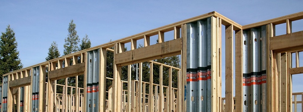
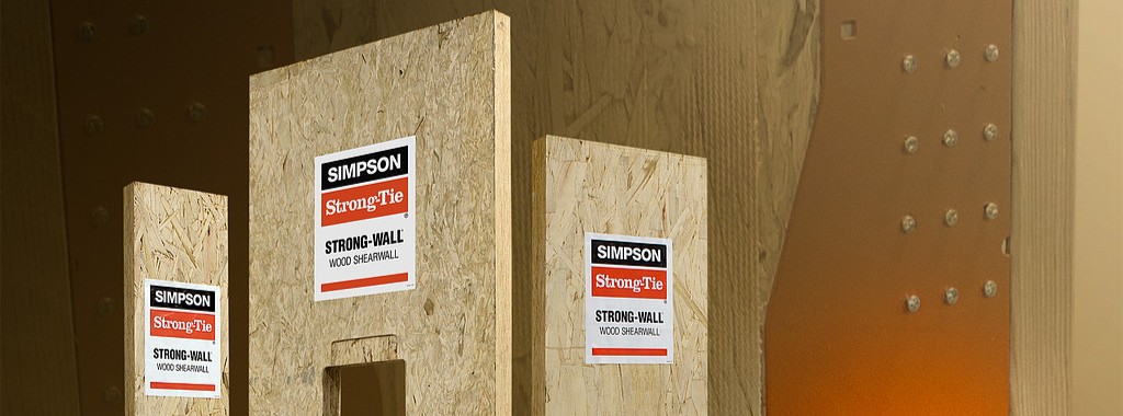
The code-listed Strong-Wall high-strength wood shearwall is an extremely versatile solution for lateral-force resistance in residential, multi-family and light-frame commercial construction.
Tenth Day of Trivia — Shearwalls
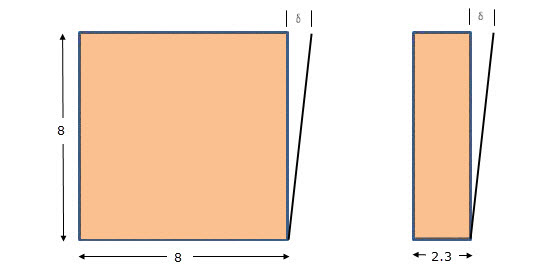
The Simpson Strong-Tie Strong-Wall® shearwall was introduced in 1999. The 1997 Uniform Building Code had incorporated restrictive 2:1 aspect ratio requirements for wood structural panel (WSP) shearwalls in high seismic areas. We conducted extensive cyclic testing of complete wall systems (not just components) to prove that narrow Strong-Wall shearwalls achieved the high performance required for seismic and wind designs.
Solving the Puzzles Presented by “As Built” Conditions
As civil and structural engineers, we know all too well that what is on the plans doesn’t always translate exactly as intended in the field. Part of what keeps our jobs interesting is having to solve problems that arise with “as built” conditions that are not always easy to change. It can feel like a complex puzzle trying to figure out what is possible when considering all aspects, including demand loads, load transfer, construction sequence, and also cost.
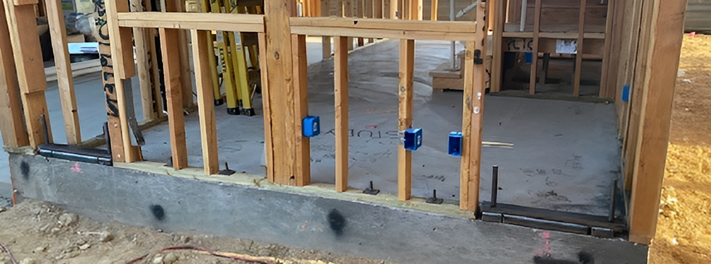
How to Accommodate Misplaced Shearwall Anchorage
For several years, the Simpson Strong-Tie Strong-Wall® research and development team has kicked around the idea of developing an “adapter” that would allow for field substitutions or accommodate misplaced Strong-Wall anchorage.

Questions Answered: Strong-Wall® High-Strength Wood Shearwall Webinar
In this post, we follow up on our July webinar, Innovations in Strength and Versatility: Overview of the Strong-Wall® High-Strength Wood Shearwall, by answering some of the interesting questions raised by attendees. Continue Reading
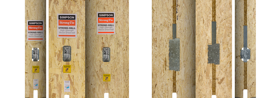
Introducing the Stronger, Simpler and More Versatile Strong-Wall® High-Strength Wood Shearwall
After years of development, we’re excited to introduce the newest member of the Strong-Wall® shearwall family – the Strong-Wall high-strength wood shearwall (WSWH).

Strong-Wall Bracing Selector: Bridging the Gap between Engineered Design and Prescriptive Construction
Asking a structural engineer to design wall bracing under the IRC® can be like asking a French pastry chef to bake a cake using Betty Crocker’s Cookbook. The temptation is to toss out the prescriptive IRC recipe and design the house using ASCE 7 loads and the AWC SDPWS shear wall provisions per the IBC®. But if only a portion of the house needs to be engineered, there may be an easier option.
The prescriptive IRC states an IBC engineered design “is permitted for all buildings and structures and parts thereof” but the design must be “compatible with the performance of the conventional framed system.” But how exactly does an IRC braced wall panel perform? The code doesn’t come right out and tell us, but there are two bracing methods that are essentially shear walls masquerading as braced wall panels: Method ABW and Method BV-WSP. Backing into their allowable loads gives us the key to determining equivalence and eliminates the need to develop lateral forces.
But before you can bust out the slide rule and start crunching numbers, you need to figure out how much bracing the prescriptive code requires. We developed our Wall-Bracing-Length Calculator in 2010 to help designers do just that. And last month, we launched our Strong-Wall® Bracing Selector tool to make it easier to specify equivalent solutions for tricky situations.
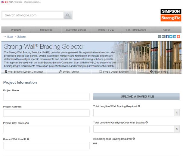

You can export the required lengths (and project information) from the Wall-Bracing-Length Calculator directly into the Strong-Wall Bracing Selector or you can manually enter in the required lengths. The selector app will provide a list of Strong-Wall panels that have an equivalent length, evaluate their anchorage loads and return a list of pre-engineered anchor solutions for a variety of foundation types.
If you’re familiar with our Strong-Wall Prescriptive Design Guide (T-SWPDG10), the selector automates this 84-page document in just a few steps. One big upgrade is the ability to select a solution to meet the exact amount of bracing that is required. If you needed 2.8-ft. of wall bracing, you have to round up to the tabulated 4-ft. solutions if you are using the guide, but now you can select a wall solution that is equivalent to 2.8-ft., which might mean a smaller wall width or better anchor options. You also have the ability to save the selector file for later modifications, create a PDF of the job-specific output, or email the PDF directly from the program.

So next time you get asked to “design” some wall bracing, see if our Wall-Bracing-Length Calculator and Strong-Wall Bracing Selector might save you some time. There is a tutorial and a design example on the Bracing Selector web page, but it’s very easy to use so you may just want to dive right in. I should also point out that the Strong-Wall SB panels have not yet been implemented into the program, but bracing information for them is available on strongtie.com in posted letters for wind (L-L-SWSBWBRCE14), seismic (L-L-SWSBSBRCE14), and seismic with masonry veneer (L-L-SWSBVBRCE14).
Let us know what you think of this new tool in the comments below.

New Treatment of Shear Wall Aspect Ratios in the 2015 SDPWS
This post was co-written by Simpson Engineer Randy Shackelford and AWC Engineer Phil Line.
The 2015 International Building Code references a newly updated 2015 Edition of the American Wood Council Special Design Provisions for Wind and Seismic standard (SDPWS). The updated SDPWS contains new provisions for design of high aspect ratio shear walls. For wood structural panels shear walls, the term high aspect ratio is considered to apply to walls with an aspect ratio greater than 2:1. These same high‑aspect‑ratio shear wall provisions have been maintained in subsequent editions of SDPWS, including the 2021 SDPWS, and remain part of current design practice.

In the 2015 SDPWS, reduction factors for high aspect ratio shear walls are no longer contained in the footnotes to Table 4.3.4 (See Figure 2). Instead, these factors are included in new provisions accounting for the reduced strength and stiffness of high aspect ratio shear walls.

Deflection Compatibility – Calculation Method
New Section 4.3.3.4.1 states that “Shear distribution to individual shear walls in a shear wall line shall provide the same calculated deflection, δsw, in each shear wall.” Using this equal deflection calculation method for distribution of shear, the unit shear assigned to each shear wall within a shear wall line varies based on its stiffness relative to that of the other shear walls in the shear wall line. Thus, a shear wall having relatively low stiffness, as is the case of a high aspect ratio shear wall within a shear wall line containing a longer shear wall, is assigned a reduced unit shear (see Figure 3).
In addition, Section 4.3.4.2 contains a new aspect ratio factor, 1.25 – 0.125h/bs, that specifically accounts for the reduced unit shear capacity of high aspect ratio shear walls. The strength reduction varies linearly from 1.00 for a 2:1 aspect ratio shear wall to 0.81 for a 3.5:1 aspect ratio shear wall. Notably, this strength reduction applies for shear walls resisting either seismic forces or wind forces. For both wind and seismic, the controlling unit shear capacity is the smaller of the values from strength criteria of 4.3.4.2 or deflection compatibility criteria or 4.3.3.4.1.
Deflection Compatibility – 2bs/h Adjustment Factor Method
The 2bs/h factor, previously addressed by footnote 1 of Table 4.3.4, is now an alternative to the equal deflection calculation method of 4.3.3.4.1 and applies to shear walls resisting either wind or seismic forces. This adjustment factor method allows the designer to distribute shear in proportion to shear wall strength provided that shear walls with high aspect ratio have strength adjusted by the 2bs/h factor. The strength reduction varies linearly from 1.00 for 2:1 aspect ratio shear walls to 0.57 for 3.5:1 aspect ratio shear walls. This adjustment factor method provides roughly similar designs to the equal deflection calculation method for a shear wall line comprised of a 1:1 aspect ratio wall segment in combination with a high aspect ratio shear wall segment.
In prior editions of SDPWS, a common misunderstanding was that the 2bs/h factor represented an actual reduction in unit shear capacity for high aspect ratio shear walls as opposed to a reduction factor to account for stiffness compatibility. The actual reduction in unit shear capacity of high aspect ratio shear walls is represented by the factor, 1.25 – 0.125h/bs, as noted previously. The 2bs/h factor is the more severe of the two factors and is not applied simultaneously with the 1.25-0.125h/bs factor.
What are the major implications for design?
- For seismic design, the 2bs/h factor method continues unchanged, but is presented as an alternative to the equal deflection method in 4.3.3.4.1 for providing deflection compatibility. The equal deflection calculation method can produce both more and less efficient designs that may result from the 2bs/h factor method depending on the relative stiffness of shear walls in the wall line. For example, design unit shear for shear wall lines comprised entirely of 3.5:1 aspect ratio shear walls can be as much as 40% greater (i.e. 0.81/0.57=1.42) than prior editions if not limited by seismic drift criteria.
- For wind design, high aspect ratio shear wall factors apply for the first time. For shear walls with 3.5:1 aspect ratio, unit shear capacity is reduced to not more than 81% of that used in prior editions. The actual reduction will vary by actual method used to account for deflection compatibility.
- The equal deflection calculation method is sensitive to many factors in the shear wall deflection calculation including hold-down slip, sheathing type and nailing, and framing moisture content. The familiar 2bs/h factor method for deflection compatibility is less sensitive to factors that affect shear wall deflection calculations and in many cases will produce more efficient designs.
As the 2015 International Building Code is adopted in various jurisdictions, designers will need to be aware of these new requirements for design of high aspect ratio shear walls. The 2015 SDPWS also contains other important revisions that designers should pay attention to. The American Wood Council provides a read-only version of the standard on their website that is available free of charge.
Please contribute your thoughts to these new requirements in the comments below.
Wood Shear Wall Design Example
Two weeks ago, I had the chance to present to the Young Members Group of the Structural Engineering Association of Metro Washington on the topic of Multi-Story Light-Frame Shear Wall Design. With all of the large firms in the D.C. area, it wasn’t a big surprise to find out that only about one-third of the group had experience with light-frame shear wall design.
However, while researching civil/structural engineering programs in the Midwest and Northeast last week (for our Structural Engineering/Architecture Student Scholarship program), I was disappointed to find that only about a quarter of the top engineering programs offer a wood design course. So I thought it might be helpful to post a wood shear wall design example this week.
The example is fairly basic but includes an individual full‑height and perforated shear wall analysis for the same condition. The design is based on wind loading and SPF framing, both common in the Midwest and Northeast, and follows the provisions and terminology of the 2021 Special Design Provisions for Wind and Seismic (SDPWS), which represent current practice for wood lateral system design.
Multi-Story Shear Wall Example: Wind Loads with SPF Framing
Given: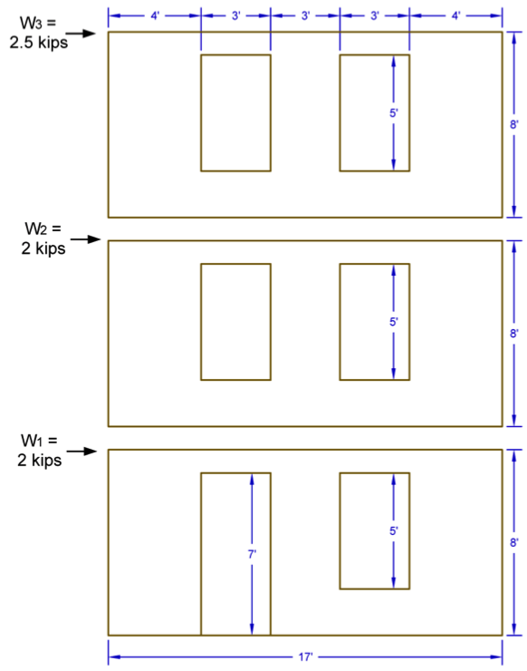
- 2021 SDPWS
- 3-Story Wood Framed Shear Wall Line
- ASD Diaphragm Shear Forces from Wind as Shown
- Wall and Opening Dimensions as Shown
Solution:
- Determine total shear force in each shear wall line.
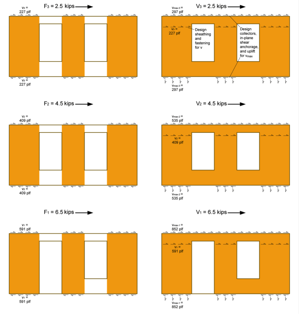
- Determine the Induced Unit Shear Force, v, for use with both shear wall types and the Maximum Induced Unit Shear Force, vmax, for the perforated shear wall collectors, shear transfer, and uniform uplift. Note the following:
- vmax requires the determination of the Shear Capacity Adjustment Factor, CO, for the perforated shear wall.
- The SDPWS provides two methods for determining CO, a tabulated value or a calculated value. This example uses the more precise calculated value.
- The perforated method requires the collectors be designed for vmax and the bottom plate to be anchored for a uniform uplift equal to vmax (as illustrated in the following figure).

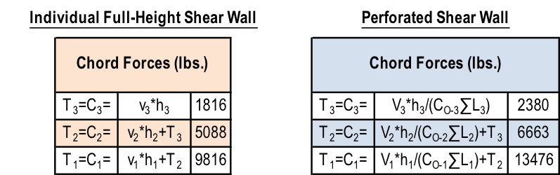
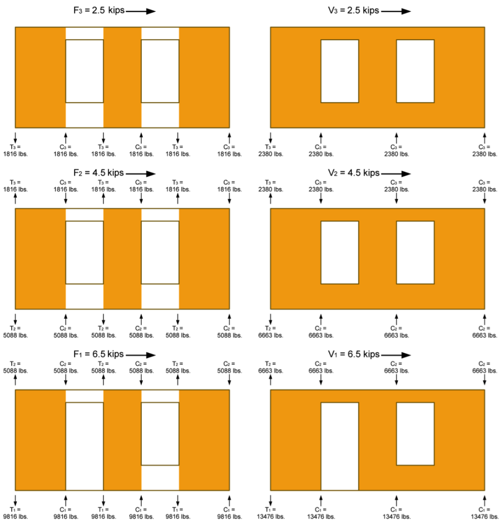
 3. Determine the Tension, T, and Compression, C, forces in the chords (assume no contribution from dead load for this example). Note the following:
-
- Reverse wind loading will require a mirror image of the T & C forces shown in the following figure.
- The tension forces, T, shown in the example reflect the cumulative tension forces as they are transferred down from post-to-post, as is typical with traditional holdowns. For continuous rod systems like ATS, the incremental tension forces (resulting from the unit shear, vor vmax, at that level only) must also be determined as shown in the shear wall specification table at the end of this example.

 4. Determine sheathing material and fastening pattern based on v calculated in Step 2. The table below is based on 7/16″ wood structural panel sheathing values from SDPWS Table 4.3A. The nominal unit shear values listed in the table shall be adjusted in accordance with SDPWS Section 4.3.3 to determine the allowable unit shear for ASD design.
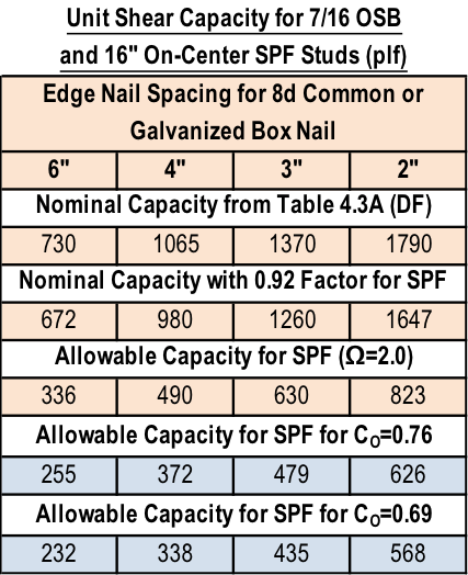
A. Individual Full-Height Shear Wall:
i. v3=227 plf: Use 7/16 OSB with a 6:12 nailing pattern which has an allowable load of 336 plf
ii. v2=409 plf: Use 7/16 OSB with a 4:12 nailing pattern which has an allowable load of 490 plf
iii. v1=591 plf: Use 7/16 OSB with a 3:12 nailing pattern which has an allowable load of 630 plf
B. Perforated Shear Wall (apply CO factor to allowable shear capacity):
i. v3=227 plf: Use 7/16 OSB with a 6:12 nailing pattern which has an allowable load of 255 plf
ii. v2=409 plf: Use 7/16 OSB with a 3:12 nailing pattern which has an allowable load of 479 plf
iii. v1=591 plf: Use 7/16 OSB on both sides of the wall with a 4:12 nailing pattern which has an allowable load of 338*2=676 plf
5. Size the posts for compression. Simpson provides some useful tables in the back of the connector catalog with allowable tension and compression loads for a variety of sizes, heights, and species of posts.
6. Select holdowns for the tensions loads and verify post sizes are sufficient. For higher aspect ratio shear walls, the post size and holdown type may significantly reduce the moment arm between center of tension and center of compression, resulting in higher tension and compression forces.
The tables below show the shear wall specification for the walls in the example in a typical format. Note that they do not include some detailing that is required for items such as the uniform uplift force on the bottom plate of all perforated shear walls, or the perforated shear walls with OSB sheathing on both sides.
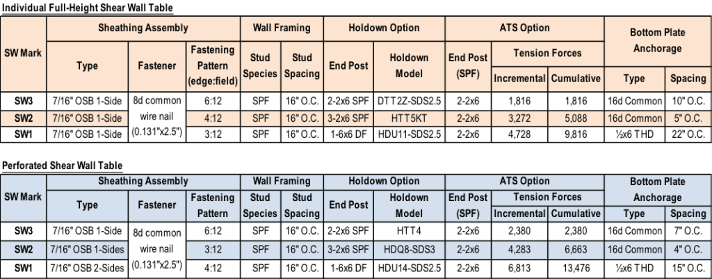
There are different ways to address the loads, so let us know if you would do anything differently in your designs.

Flexible or Rigid? Multi-Story Light-Frame Structure Design Considerations
I like to think I’m flexible, but I’ve been accused of being rigid at times. I guess that’s what therapy is for. If you were to ask a light-frame structure diaphragm that same question, you would likely get multiple conflicting answers. The 1988 UBC first introduced parameters to evaluate diaphragm rigidity. Earthquake Regulations Section 2312(e)6 stated:

Provision shall be made for the increased shears resulting from horizontal torsion where diaphragms are not flexible. Diaphragms shall be considered flexible for the purposes of this paragraph when the maximum lateral deformation of the diaphragm is more than two times the average story drift of the associated story. This may be determined by comparing the computed midpoint in-plane deflection of the diaphragm under lateral load with the story drift of adjoining vertical resisting elements under equivalent tributary lateral load.