The transition from one building code to the next always begs the question, “how is the newer code different?” There are several changes between the 2009 IBC and 2012 IBC that will change the way designers approach seismic design. This blog post is a broad overview of some of the changes. Since it’s not practical to cover all the changes between the previous and new codes in detail in one post, the discussion will be mainly on 2012 IBC and the corresponding ASCE7-10 reference standard.
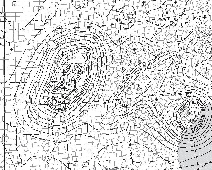
Seismic ground motion map
The seismic ground motion maps have been updated to match ASCE7-10. The titles of the maps in IBC were revised from “Maximum Considered Earthquake Ground Motion” to “Risk-Targeted Maximum Considered Earthquake (MCER) Ground Motion Response Accelerations” in order to reflect the titles in 2009 NEHRP and ASCE 7-10. As in previous editions, some areas will prove difficult to read due to the contour lines, so the USGS site and GPS coordinates are recommended (http://earthquake.usgs.gov). Additional information about changes made for 2009 NEHRP is available at www.nibs.org or www.bssconline.org.
The term “occupancy category” was replaced with “risk category” in the 2012 IBC for consistency with the term used in ASCE 7-10. This change was made because it was decided that the use of the word “occupancy” implied the category was directly tied to occupancy classifications in the code, while the word “risk” more accurately communicates that the category is based on acceptable risk of failure.
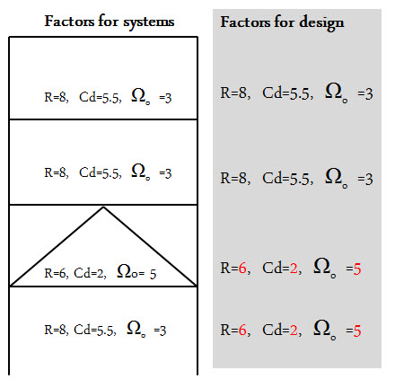
ASCE7-10 revised the way designers use the corresponding Drift amplification, Cd, and Overstrength factor, Ωo, of the Response modification factor, R. In ASCE7-05, when there is a vertical combination of different R-values, the Cd, and Ωo cannot decrease as you go down each level of a building. In ASCE7-10 (12.2.3.1), the Cd and Ωo always correspond to the R-Value as you go down. The adjacent figure illustrates the new provision to use the corresponding Cd, and Ωo with the R-value at each level.
ASCE7-10 (12.3.4.1) added a clarification for out-of-plane anchorage forces where the redundancy factor, p = 1.0. The intent of the redundancy factor was to ensure the vertical seismic-resisting system with insufficient redundancy had adequate strength. The design forces for out-of-plane wall loading are not redundancy requirements. ASCE7-10 (12.11.12) revised the out-of-plane wall anchorage force equation where the anchorage forces are reduced for shorter diaphragm spans.
Light-frame construction structures are no longer exempt from amplification of accidental torsion in ASCE7-10 (12.8.4.3). There are many structures vulnerable to torsional effects including some “tuck under” parking buildings that are often light-frame structures. See posts titled Soft-Story Retrofits and City of San Francisco Implements Soft-Story Retrofit Ordinance for more discussion of soft-story, light-frame buildings.
This is just a brief summary of changes related to seismic design found in the 2012 IBC. What are other changes that will modify your approach to seismic design?
For the first time, ACI 318 – 11 includes a design provision for adhesive anchors in concrete. Previously, adhesive anchors were designed according to provisions found in both ICC Evaluation Service (ICC-ES) AC308 and ACI 318 – 08. A relatively new standard, ACI 355.4, must be used to qualify adhesive anchors in concrete. This new standard, along with ACI 318 – 11, contains important changes that will affect anchor systems designed to the 2012 IBC. Not all changes are discussed here. I will only focus on what you – the engineer – should be aware of.
ACI 355.4 requires that adhesive anchors in concrete be evaluated using a bond strength (measured in terms of psi and used with the surface area of the embedded portion of the anchor) that corresponds to a long-term temperature (LTT) of 110 degrees F to account for potential elevated temperature exposure conditions. This wasn’t necessarily the case previously where, for example, the engineer could elect to use a temperature category that listed bond strength values based on a LTT of 75 degrees F. The issue here is creep.
Creep, in the world of adhesive anchors, looks at how well the anchor can resist load without too much axial displacement over a period of not minutes, not hours, not even years but decades. As a general rule, it’s no surprise that creep worsens as the temperature rises for almost any material. In our case, the bond strength is effectively reduced. Most adhesives, if not all, currently list bond strength values that correspond to a LTT of 110 degrees F. Make sure to select the temperature category that meets this minimum requirement. Some adhesives will experience a reduction in bond strength at an LTT of 110 degrees F, some won’t.
What about applications involving short-term-only loading? Is creep still relevant? Generally, you’ll find that adhesive anchors negatively impacted by the higher LTT requirement will gain back much of their load for seismic/wind-only load applications. So creep becomes irrelevant.
While adhesive anchors used solely for the purpose of resisting short-term loads will remain largely unaffected by this code change, significant changes have been made to the design and installation of adhesive anchors when used for sustained loading applications (e.g. dead load, live load, etc.).
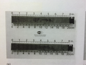
First, the bond strength must be reduced by a factor of 0.55 as compared to 0.75 under the previous code (following ICC-ES AC308). New to the code, section D.9.2.2 of ACI 318 App. D requires that adhesive anchors used for resisting sustained loads be installed by someone who has taken the Adhesive Anchor Installation Certification (AAIC) program. The installer must show proof that he/she is certified by passing both a written and performance examination. Installing adhesive overhead requires some skill. So it’s no surprise that the installer must satisfactorily demonstrate proficiency by blindly installing adhesive overhead into an inverted test tube that will later be cut in half and graded for the presence of voids. Figure 1 shows no voids, so the installer passed.
Figure 1 [from ACI-CRSI Installer Workbook Publication CP-80 (12)]However, exceptions do exist. If you’re working on a hospital or school in California, the 2013 CBC (Table 1705A.3 footnote c) requires that all horizontal and overhead adhesives anchors – irrespective of load condition – be installed by a Certified Adhesive Anchor Installer (CAAI). This deviates from ACI 318 D.9.2.2.
Arguably, with AAIC, there’s an added cost to using adhesives for anchorage designed for sustained loading. However, for sustained loading applications best suited for adhesive anchors it should come as peace of mind to the engineer, owner, contractor and other parties involved with the construction project that a certified installer has been employed to ensure that the adhesive anchor has been installed in accordance with the manufacturer’s printed installation instructions.
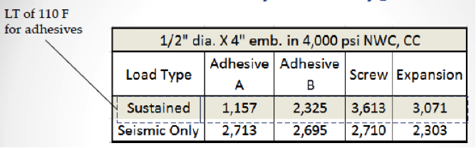
While the engineer should be aware of the above limitations placed on adhesive anchors, by no means should it hamper their design. There are several options available to the engineer. Table 1 compares the tensile design strength of three common types of anchors – two adhesives, two mechanical anchors (one screw and one expansion type) – determined using the new design provision ACI 318 -11. While the creep test results show a reduced capacity for adhesive A, it does show a significant increase in load for seismic-only applications because , as we discussed earlier, creep is no longer an issue. Some adhesives, like adhesive B, will do well under the creep test (at an elevated LTT of 110 degrees F), so any capacity increase for seismic-only applications will be small.
Table 1
What three important points can we glean from Table 1? First, all things being equal, mechanical anchors will typically achieve higher “code values” for sustained loading applications relative to adhesives. Second, mechanical anchors are easier to install overhead. Third, AAIC is not required for mechanical anchors. While these reasons support using mechanical anchors for overhead anchorage, doing so is nothing new. The bulk of overhead attachments have almost always been made with mechanical anchors mainly because it’s just easier to do it that way.
Perhaps up to 95% of adhesives are used to secure rebar to concrete – we’ll call them rebar dowels. Like any anchor, rebar dowels can be used to resist seismic and/or sustained loads. While the exact breakdown is hard to determine, arguably, the bulk of rebar dowels in the west coast are found in seismic retrofits and renovations used to thicken walls, tie-in new concrete shear walls, connect new drag struts, strengthen existing concrete elements, etc., all for the purpose of strengthening the lateral capacity of the existing structure to withstand greater earthquake and/or wind loads. These typically won’t require a CAAI, but it might if it’s a school or hospital project that requires overhead or horizontal anchors. Some rebar dowels are used for enlarging footings to withstand greater dead and live loads, so these would require a CAAI. Remember: the bond strength can be lower than expected for sustained loading applications, so you may want to use an adhesive that does well at a LTT of 110 degrees F if that’s what your design requires.
One new benefit of ACI 318 is that the engineer can now design adhesive anchors to go into lightweight concrete using the factors found in section D.3.6.
One significant change engineers should include in their specification is that the concrete must be aged at least 21 days before installing an adhesive. Previously, the industry standard was to wait seven days. For additional information regarding adhesives installed into younger normal-weight concrete, read the following Simpson Strong-Tie engineering letter: http://www.strongtie.com/ftp/letters/generic/L-A-ADHGRNCON14.pdf
What are you experiencing in the design of your anchors in your jurisdictions? Leave a comment down below because we would like to know.
In February 2007 I had the opportunity to volunteer for a Soft-Story Sidewalk Survey for the San Francisco Department of Building Inspection. The purpose of the survey was to inventory buildings in San Francisco that appeared superficially to have soft or weak first stories. The volunteers were given a list of addresses to review and we recorded if the building was more than three stories tall, had five or more dwellings, and estimated what percentage of the ground level had openings in the walls. No structural analysis going on, just counting stories, mailboxes, doors and windows.
San Francisco soft-story structure failure. Photo credit: USGS.A collapsed soft-story in San Francisco from the 1989 Loma Prieta earthquake. Photo credit: Adam Teitelbaum, AFP, Getty Images.
We use cookies on this site to enhance your user experience. By clicking "I AGREE" below, you are giving your consent for us to set cookies. Privacy PolicyI AGREE
Privacy & Cookies Policy
Privacy Overview
This website uses cookies to improve your experience while you navigate through the website. Out of these cookies, the cookies that are categorized as necessary are stored on your browser as they are essential for the working of basic functionalities...
Necessary cookies are absolutely essential for the website to function properly. This category only includes cookies that ensures basic functionalities and security features of the website. These cookies do not store any personal information.
Any cookies that may not be particularly necessary for the website to function and is used specifically to collect user personal data via analytics, ads, other embedded contents are termed as non-necessary cookies. It is mandatory to procure user consent prior to running these cookies on your website.


 ASCE7-10 revised the way designers use the corresponding Drift amplification, Cd, and Overstrength factor, Ωo, of the Response modification factor, R. In ASCE7-05, when there is a vertical combination of different R-values, the Cd, and Ωo cannot decrease as you go down each level of a building. In ASCE7-10 (12.2.3.1), the Cd and Ωo always correspond to the R-Value as you go down. The adjacent figure illustrates the new provision to use the corresponding Cd, and Ωo with the R-value at each level.
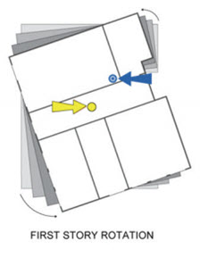 Light-frame construction structures are no longer exempt from amplification of accidental torsion in ASCE7-10 (12.8.4.3). There are many structures vulnerable to torsional effects including some “tuck under” parking buildings that are often light-frame structures. See posts titled Soft-Story Retrofits and City of San Francisco Implements Soft-Story Retrofit Ordinance for more discussion of soft-story, light-frame buildings.