Vertical deflection resulting from live and dead loads – of both roof and floor framing components – is an important serviceability consideration in the overall design of the building. And while this could be a blog topic in and of itself, this post is instead going to focus on two other types of truss movements that often prompt questions: seasonal up-and-down movement (of the trusses relative to the walls) and horizontal movement (of scissor trusses).
On the one hand, these are completely different topics. But on the other hand, they both deal with movement; which needs to be properly addressed when incorporating trusses into the overall building. So it’s sensible to discuss them together in one blog post.
Seasonal Up-and-Down Movement
This type of movement goes by many different names that might sound familiar – truss arching, truss uplift, partition separation, or – to use the most formal name – ceiling-floor partition separation. All of these names describe the separation that develops between interior partition walls and ceiling finishes, which can cause gaps in the drywall to open in the winter and close in the summer. This movement is often considered to be a truss issue; however, it is not always the trusses that do the moving, but rather the walls or floors, or both, beneath the trusses.
This issue is also not limited to truss construction, but can also occur with other types of wood construction. The truss industry has information on this topic to help educate the market about the causes of ceiling-floor partition separation, best practices and construction techniques for minimizing the movement, and how to accommodate this movement in the structure to prevent drywall cracking.
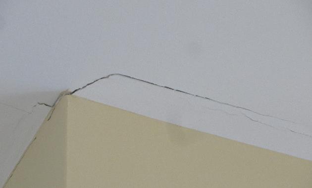
For those who are interested in a very thorough and technical discussion of this issue and all of the factors that can contribute to it, there is a Technical Note available from the Truss Plate Institute (TPI) called Ceiling-Floor Partition Separation: What Is It and Why Is It Occurring? Although it was written several years ago (by the Small Homes Council-Building Research Council), the information remains relevant because the problem and its causes are the same now as they were then. The Technical Note discusses the potential causes of ceiling-floor partition separation, which may include one or more of the following: attic moisture (and the differential shrinkage and swelling of truss chords due to seasonal changes in moisture content), foundation settlement, expansive soils, excessive cumulative shrinkage of wood framing members and errors made during the construction process such as pulling the camber out of a truss to attach it to a partition. There is even an Appendix with a brief discussion of longitudinal shrinkage and an example calculation showing how much upward deflection results when a truss arches because of differential shrinkage.
For a condensed version, there is also a document available from the Structural Building Components Association (SBCA) called “Partition Separation Prevention and Solutions (How to Minimize Callbacks Due to Gypsum Cracking at the Wall/Ceiling Interface)”. This single-page document is particularly useful for educating the industry to take the appropriate preventive measures during construction, which help minimize problems later.
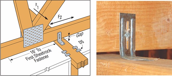
For example, the use of slotted roof truss clips – such as our STC (see below) – is one preventive measure, since these clips allow for vertical movement, but still provide lateral support at the top of the wall. DS drywall clips can be used in conjunction with the STC clips to secure the drywall to the wall. Then, to allow the drywall ceiling to “float,” the drywall is not fastened to the bottom chord within 16” from the wall. Taking these steps allows movement between the truss and the wall, without causing cracking in the drywall at the wall/ceiling interface.
It is important to note that, while foundation settlement may indicate a structural problem and can be prevented by proper design, truss arching resulting from the natural shrinking/swelling of wood does not indicate any structural problem and cannot be avoided in the design process.
Horizontal Movement of Scissor Trusses
In the typical design of a scissor truss, a pin-type bearing is used at one end, and a roller-type bearing is used at the other end, which results in some amount of horizontal deflection at the roller bearing.
The bearing assumptions used in the design of a scissor truss are important not only to the truss, but they also have design implications for the building as well. Using a pin-type bearing at both ends of the truss has undoubtedly been a temptation to every truss technician at one time or another, when the same scissor truss that is failing the analysis suddenly works as soon as the bearings are switched from pin-roller to pin-pin. Unfortunately, that isn’t a valid option unless the walls are infinitely stiff (which they typically aren’t), or unless special measures are taken to resist the horizontal thrust that develops at the pinned reactions. In most cases, such measures won’t be taken which means with the exception of some rare cases, scissor trusses must be designed with pin-roller bearings.
The horizontal deflection that results when a scissor truss is designed with a roller bearing on one end prompts further questions and discussion. What happens when a scissor truss is rigidly secured to the walls of the building – how does that horizontal movement happen? How much horizontal movement is too much? Should the scissor truss be attached to the wall with a sliding (roller-like) connection?
First, a scissor truss that is rigidly secured to both walls will still experience horizontal movement due to the flexibility of the building’s construction in most residential and light commercial construction. How much horizontal movement is too much for the building? This is definitely a question that the Building Designer needs to answer based on his/her evaluation of the overall structure. However, there are a couple of resources that can provide some insight.
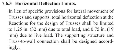
ANSI/TPI 1 has the following provision:
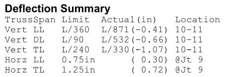
Per ANSI/TPI 1, a scissor truss can have up to 1.25″ of total horizontal deflection in the absence of stricter limits from the Building Designer. Scissor trusses may even be designed with more than this amount of horizontal deflection, along with a warning that special provisions for lateral movement may be required. It is important for the Building Designer to be aware of the calculated horizontal movement of the scissor truss, as reported on the truss design drawing, to ensure that it is an acceptable amount of horizontal movement for the supporting structure and/or to determine whether special provisions for the lateral movement need to be made.
While 1.25″ of total horizontal deflection may seem like a lot of horizontal movement, these calculated horizontal deflections are considered to be conservative; many Designers agree that the predicted movement from the pin-roller bearing combination is greater than will actually occur in the constructed building. This is based on the fact that the design loads may be overstated and the contribution of the sheathing (and drywall if applicable) to resist the horizontal movement is not taken into account during the analysis of the truss.
The National Building Code of Canada (NBC) references Section 5.4.4 of the 2009 Engineering Guide for Wood Frame Construction, which limits lateral movement at the top of each wall to h/500. This correlates to a total allowable horizontal movement of 3/8″ for 8ˈ walls. However, the Canadian truss design standard (TPIC-2014) permits trusses to have a horizontal deflection (at the roller support) of up to 1″. In this case, since the horizontal deflection of the truss exceeds the allowable horizontal deflection of the wall, a sliding connection needs to be used between the truss and the wall.
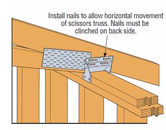
There are different opinions on the use of sliding connections, such as the slotted TC24 or TC26 connectors (see below), which allow for horizontal movement of the trusses without pushing out the wall, and also provide uplift resistance. The use of these clips also varies greatly by region. There are many places where these clips are used regularly and successfully. However, some Designers prefer to restrict the truss horizontal deflection and require the use of a positive connection between the scissor truss and the wall plate due to concerns regarding the transfer of lateral loads from the top of wall to the roof diaphragm. When TC connectors are used, they are often used on alternating ends of the trusses so that there is a positive connection along each wall at every other truss. Some Designers feel this approach minimizes the horizontal movement between the truss and the wall after the building is constructed and fully sheathed and braced.
There is not a single correct answer to address horizontal truss movement for every building. The amount of horizontal movement that is acceptable for the structure and whether or not a sliding connection should be used will depend on the building, the loading conditions, the designer’s experience and/or judgment, and, in some cases, the local building jurisdiction. What is more important than the decision to either restrict horizontal deflection or utilize sliding connectors like the TC24/TC26 (both have been successful) is that the bearing assumptions used in the design of the scissor truss are accounted for in the design of the building. The worst-case scenario is when a scissor truss is designed with a pin-pin bearing and installed in a building where absolutely no measures have been taken to supply the needed resistance to the calculated horizontal thrust.
What are your thoughts or experiences with either seasonal up-and-down movement or horizontal movement? Let us know in the comments below!

