In an ideal world, a building is envisioned and a structural engineer begins the structural design. When the decision to use roof trusses is made, a component manufacturer is promptly involved in the design process. Using the loads and design parameters from the structural engineer, the trusses are designed and those designs are provided back to the engineer. The structural engineer then incorporates the truss designs into the building, transfers the loads through the structure and designs all the structural elements, bracing and connections necessary to provide a continuous load path down to the foundation. Finally, working from the complete and detailed plans, the contractor constructs the building flawlessly. Perfection!
But let’s get back to reality, where buildings are often designed and ground broken by the time the trusses are designed. The building Designer creates a roof framing plan to analyze and transfer the loads between the roof system and the rest of the building, and then designs the building (from the top plate down) accordingly. The component manufacturer (CM) eventually gets the plans and uses them to create a truss placement diagram and gather the truss design criteria. The CM then communicates the truss design parameters to the truss design engineer, who designs each of the individual trusses. The CM provides those truss designs and the truss placement diagram back to the building Designer. So far so good, right?
If every building were rectangular with a gable-style roof, this process would be fairly simple and hassle-free. But buildings are often more complicated than that. Roof systems can get very complex, so things don’t always go according to plan…such as when a wall that was intended to be non-load bearing gets used as a bearing location for the trusses; or when the CM moves a girder to a different location that works better for the trusses. Or maybe a truss can’t be designed for the entire span and an additional support is needed. In some cases, the CM may even flip the direction of the trusses completely because it results in a more efficient (lower-cost) truss package – that’s better for the building, right?
Changes during the design process can result in additional labor, material and cost. In today’s fast-tracked world, how can these expenses be avoided? Below are some suggestions from a truss Designer’s perspective.
Know each party’s design responsibilities
This may not seem like it has much to do with minimizing changes during the design process, but some problems arise from the fact that there is not always a common understanding of each party’s responsibilities. One misconception is that truss design engineers design an entire roof system, and they design the roof truss system to work within the framework of the building as set forth in the building structural plans. This is not true! Truss design engineers design single components, not systems. They do not even see the building Designer’s plans. It is the CM that receives the construction documents to obtain the truss design criteria and requirements. They in turn communicate the truss design parameters to the truss design engineer.
It is also important to understand the role the truss placement diagram plays in the overall process. This is a commonly misunderstood document, because many people think this is an engineered document prepared by the truss design engineer. Not only do truss design engineers not prepare these documents, they do not even review them. Instead, the CM creates the truss placement diagram after reviewing the construction documents. A truss placement diagram is only intended to identify the assumed location for each truss and serve as a truss installation aid. In fact, the truss industry intentionally changed the description of this document at one point from “truss placement plan” to “truss placement diagram” because the word “plan” has a connotation associated with engineering and design, and a truss placement diagram does not involve either of those.
Understanding how the truss industry operates and the responsibilities each party has in the design process will prevent incorrect assumptions from being made. If you find yourself saying, “I’m sure the truss design engineer will check this and take care of it…,” you probably need to think again.

The clearer the specifications, the better
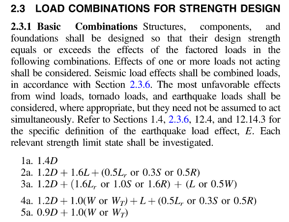
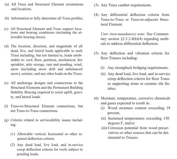
This may seem obvious, but do the construction documents contain all of the information necessary for the preparation of the truss design drawings? ANSI/TPI 1 specifies the required information in the construction documents (see text box below). Anything less than this information will mean assumptions need to be made during the creation of the truss placement diagram and the design of the trusses. The building Designer can also specify additional requirements to help ensure that the trusses they get are the trusses they want. In short, the more complete, accurate and detailed the construction documents are, the better the design process will be.
Review, review, review
It is the building Designer’s responsibility to review (and approve or reject) both the truss placement diagram and the individual truss design drawings for conformance with the overall building design. As mentioned earlier, the truss design engineer is solely responsible for the design of the individual trusses; they do not review the entire truss system and they do not check to see that the truss placement diagram meets the intent of the framing plan and specifications. Further, the component manufacturer relies on the completeness and accuracy of the information in the construction documents to create the truss placement diagram and to communicate the truss design requirements to the truss design engineer. Therefore, the success of the building’s construction depends on the building Designer’s thorough review of the truss submittal package.
Collaboration is key
Building Designers know what is best for the overall building; component manufacturers know what is best for the trusses. The best-case scenario is when the building gets the best of both. This requires collaboration during the planning stages, so that the strengths of both parties can be utilized to their maximum potential. A building Designer who finds out from the CM what the best setback distance is for a particular hip roof will not only minimize changes to the design downstream, but will also likely end up with a lower-cost building. On the other hand, a building Designer who provides some input into the actual truss designs, such as strategically placed webs in a string of trusses, will end up with a more efficient, permanent bracing plan that can even be included in the original construction documents.
Some may think the answer to this design process challenge is to let the building Designers design the trusses themselves; that all they need is the truss design software and they can design the trusses as part of their building design. But the truss industry knows that truss design software cannot replace the ingenuity and creativity of talented CMs who have a passion for what they do; just the same way that engineering software cannot ever replace an experienced engineer. That is why the truss industry continues to work hard to make it easier to collaborate, in lieu of providing truss design software to people outside of the component manufacturing industry. In this way, everyone’s skill sets can be fully utilized.
What do you think about this challenge? Let us know your thoughts in the comments below!