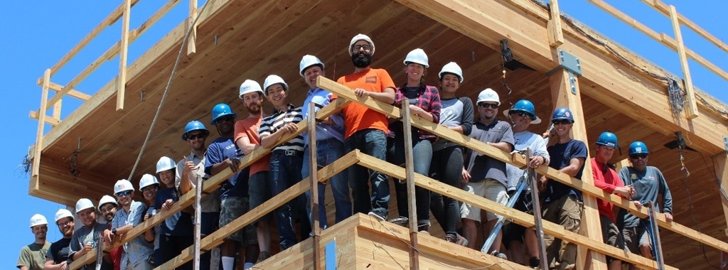
Brian DeMeza’s journey from pursuing his Master of Science degree at Oregon State University (OSU) to his current role as a Senior Field Engineer at Simpson Strong-Tie has brought him full circle with his recent involvement in the six-story NHERI TallWood project. His hands-on experience in this project played a pivotal role in shaping his passion and focus on mass timber as a potential career path.
Tag: SDWH
Revisiting Spanning the Gap
Three years ago, we created this blog post based on a technical support question we often receive about allowable fastener loads for ledgers to wood framing over gypsum board. Given that this is still a frequent question and a relevant topic, we decided to revisit the post and update it.
Drywall. Wall board. Sheetrock. Sackett Board? A product called Sackett Board was invented in the 1890s, which was made by plastering within wool felt paper. United States Gypsum Corporation refined Sackett Board for several years until 1916, when they developed a new method of producing boards with a single layer of plaster and paper. This innovation was eventually branded SHEETROCK®. More details about the history of USG can be found here.
No matter what you call it, gypsum board is found in almost every type of construction. Architects use it for sound and fire ratings, while structural engineers need to account for its weight in our load calculations. A common technical support question we receive is for allowable fastener loads for ledgers to wood framing over gypsum board.
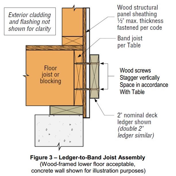
One method to evaluate a fastener spanning across gypsum board is to treat the gypsum material as an air gap. Technical Report 12, General Dowel Equations for Calculating Lateral Connection Values, is published by the American Wood Council.

TR12 has yield limit equations that allow a designer to account for a gap between the main member and side member of a connection. With a gap of zero (g=0), the TR12 equations provide the same results as the NDS yield limit equations.
![Technical Report 12 Yield Limit Equations[1]](https://seblog.strongtie.com/wp-content/uploads/2014/01/Technical-Report-12-Yield-Limit-Equations1.jpg)
Testing, of course! In So, What’s Behind a Screw’s Allowable Load? I discussed the methods used to load rate a proprietary fastener such as the Simpson Strong-Tie® Strong-Drive® SDS or SDW screws. To recap, ICC-ES Acceptance Criteria for Alternate Dowel Type Fasteners, AC233, allows you to calculate and do verification tests, or load rate based on testing alone. We develop our allowable loads primarily by testing, as the performance enhancing features and material optimizations in our fasteners are not addressed by NDS equations.
So to determine the performance of a fastener installed through gypsum board, we tested the fastener through gypsum board. This is easier to do if you happen to have a test lab with a lot of wood and fasteners in it. We did have to run down to the local hardware store to pick up gypsum board for the testing.
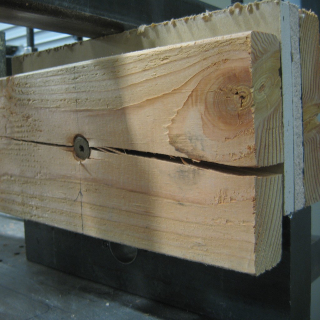
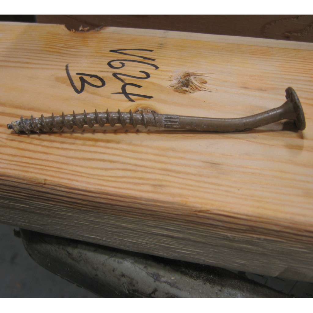
A full set of allowable loads for Strong-Drive SDWH and SDWS are available on strongtie.com. The information is given as single fastener shear values for engineered design, and also screw spacing tables for common ledger configurations. As much fun as writing spreadsheets to do the Technical Report 12 calculations is, having tabulated values based on testing is much easier.
Fastening Systems
In the fastener marketplace, Simpson Strong-Tie stands apart from the rest. Quality and reliability is our top priority.
How do you Design Sole-Plate-To-Rim-Board Attachments?
For many years, builders have struggled with the awkward sole-plate-to-rim-board attachment. They often install a few nails and call it good, resulting in a connection with significantly less capacity than needed. This connection is critical to ensure that seismic and wind loads are adequately transferred to the lateral-force-resisting system. With screws becoming much more common in construction, we saw an opportunity to address this problem.
We offer a variety of structural wood screws that have shank diameters ranging from 0.135″ to 0.244″. They form our Strong-Drive® line of structural fasteners. The Simpson Strong-Tie® Strong-Drive SDWC Truss, SDWH Timber-Hex, SDWS Timber, SDWV Sole-to-Rim and SDS Heavy-Duty Connector structural wood screws as shown in Figure 1 can be used to attach sole plates to a rim board as shown in Figure 2. These screws provide structural integrity in the wall-to-floor connection.
The sole-to-rim connection is considered a dry service location. When the sole plate and the rim are both clean wood (not treated), then any of the screws can be used as long as they meet the design loads. However, if one or both members of the connection are treated with fire retardants or preservatives, then you must use the SDWS Timber screw, SDWH Timber-Hex screw or SDS Heavy-Duty Connector screw. The SDWS, SDWH and SDS screws all have corrosion-resistance ratings in their evaluation reports.
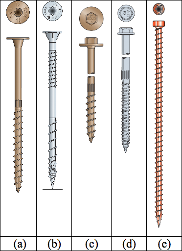
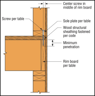
The Strong-Drive SDWV structural wood screw has the smallest diameter among these screws. The SDWV is 4″ long and has a 0.135″- diameter shank, and a large 0.400″-diameter ribbed-head with a deep six-lobe recess to provide clean countersinking. It is designed to be fast driving with very low torque. The Strong-Drive SDWS offers one of the larger diameters. It has a 0.220″-diameter shank and is offered in lengths of 4″, 5″ and 6″. It has a large 0.750″-diameter washer head which provides maximum bearing area. Longer screws allow designers to meet the minimum penetration requirement into a rim board, when the sole plate is a 3x or a double 2x member.
We have tested various combinations of sole plates, floor sheathing, and rim boards. Typical test assemblies were built and tested with two (2) Strong-Drive® screws spaced at either 3″ or 6″. Results were analyzed per ICC-ES AC233, “Acceptance Criteria for Alternate Dowel-type Threaded Fasteners.” The allowable loads listed in Table 1 are based on the average ultimate test load of at least 10 tests, divided by a safety factor of 5.0, and are rated per single fastener. The results of these tests can be found in the engineering letter L-F-SOLRMSCRW16.
The evaluated sole plates include southern pine (SP), Douglas fir-larch (DF), hem-fir (HF), and spruce-pine-fir (SPF) in single 2x, 3x or double 2x configurations. Floor sheathing thicknesses are allowed up to 1 1/8″ thick. Rim boards can be LVL or LSL structural composite lumber or DF, SP, HF or SPF sawn lumber. The load rating also assumes that the floor sheathing is fastened separately and per code.
See strongtie.com for evaluation report information if it is needed.
As a Designer, you can specify any of these Strong-Drive screws that fit your design requirements. Please visit our website and download L-F-SOLRMSCRW16 for more details.
Good luck!
Pile Construction Fasteners – New and Expanded Applications
The majority of Simpson Strong-Tie fasteners are used to secure small, solid-sawn lumber and engineered wood members. However, there is a segment in the construction world where large piles are the norm. Pile framing is common in piers along the coast, elevated houses along the beach, and docks and boardwalks.
While the term “pile” is generic, the piles themselves are not generic. They come in both square and round shapes, as well as an array of sizes, and they vary greatly based on region. The most common pile sizes are 8 inches, 10 inches, and 12 inches, square and round, but they can be found in other sizes. The 8-inch and 10-inch round piles are usually supplied in their natural shape, while 12-inch round piles are often shaped to ensure a consistent diameter and straightness. All piles are preservative-treated.
Historically, the attachment of framing to piles has been done with bolts. This is a very labor-intensive method of construction, but for many years there was no viable fastener alternative. Two years ago, however, Simpson Strong-Tie introduced a new screw, the Strong-Drive® SDWH Timber-Hex HDG screw (SDWH27G), specifically designed for pile- framing construction needs. It can be installed without predrilling and is hot-dip galvanized (ASTM A153, Class C) for exterior applications.

Simpson Strong-Tie tested a number of different pile-framing connections that can be made with the SDWH27G screw. This blog post will highlight some of the tested connections. More information can be found in the following three documents on our website:
- The flier for the SDWH Timber-Hex HDG screw: F-FSDWHHDG14 found here.
- The engineering letter for Square Piles found here.
- The engineering letter for Round Piles found here.
The flier provides product information, and the engineering letters include dimensional details for common pile-framing connections that were tested.
Piles are typically notched or coped to receive a horizontal framing member called a “stringer.” The coped shoulder provides bearing for the stringer and serves as a means of transferring gravity load to the pile. The SDWH27G can be used to fasten framing to coped and non-coped round and square piles.
The connections that we tested can be put into four general groups that include both round and square piles:
- Two-side framing on coped and non-coped piles
- One–side framing on coped and non-coped piles
- Corner framing on coped piles
- Bracing connections
Additionally, the testing program included four different framing materials in several thicknesses and depths:
- Glulam
- Parallam
- Sawn lumber
- LSL/LVL
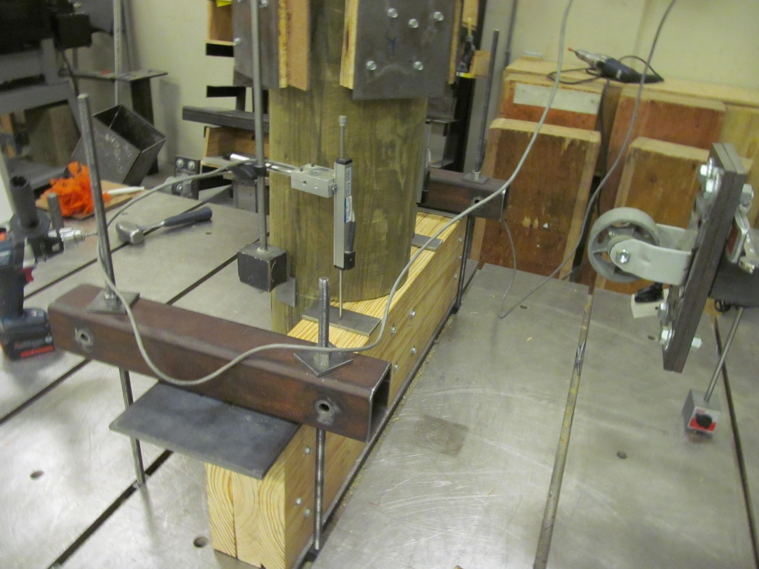
The total testing program included more than 50 connection conditions that represented pile shape and size, framing material and thickness and framing orientation and details. We assigned allowable uplift and lateral properties to the tested connections using the analysis methods of ICC-ES AC13. Figures 2 and 3 show some of the tested assemblies.
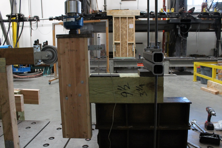
Figures 4 through 9 illustrate some of the connections and details that are presented in the flier and engineering letters.
Some elements of practice are important to the design of pile-framing connections. Some of the basic practices include:
- For coped connections, the coped section shall not be more than 50% of the cross-section.
- For coped connections, the coped shoulder should be as wide as the framing member(s).
- Fastener spacing is critical to the capacity of the connection.
- When installing fasteners from two directions, lay out the fasteners so that they do not intersect.
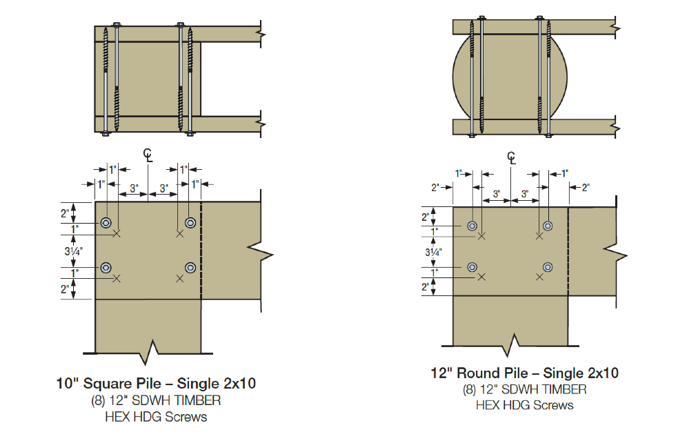
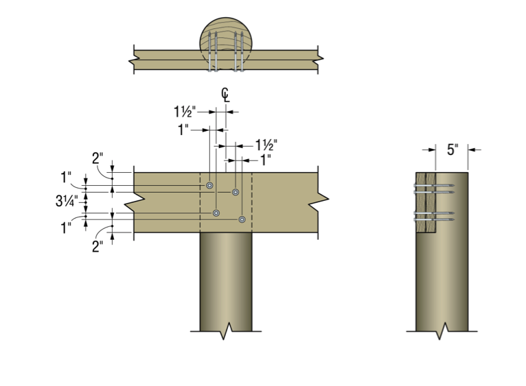
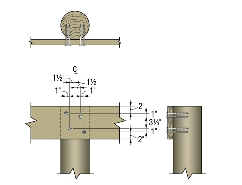
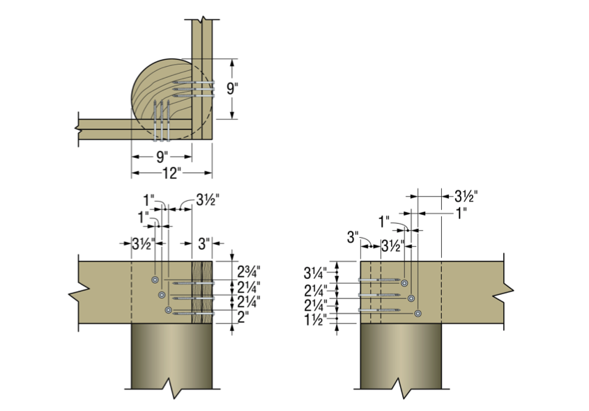
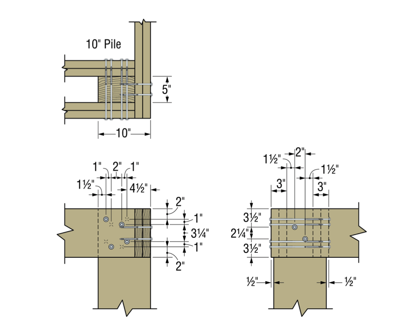
In many cases, pile-framing connections use angled braces for extra lateral support. The SDWH27G can be used in these cases too.
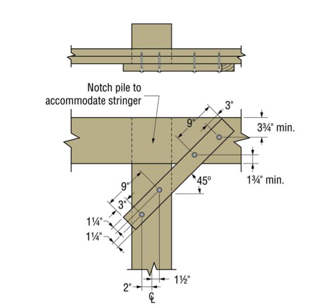
In the flier and engineering letters previously referenced, you will find allowable loads and specific fastener specifications for many combinations of stringer and pile types and sizes.
What have you seen in your area? Let us know – perhaps we can add your conditions to our list.

