

Lag screws are traditionally specified for many structural loads in wood construction. However, recent innovations in engineering for self-tapping wood screws have made them an increasingly popular, labor-saving alternative to lag screws. In the following post, Aram Khachadourian, P.E., of Simpson Strong-Tie discusses the structural and economic advantages of this option.
Continue Reading
Author: Aram Khachadourian
Aram Khachadourian, R&D Engineering Manager for Fastening Systems and Mechanical Anchors. Since joining Simpson Strong-Tie 26 years ago, he has designed and tested fasteners, holdowns, hangers, truss connectors, and anchor bolts. He has drafted numerous acceptance criteria as well as quality standards. His current focus is managing the research and development of fasteners, tools, and mechanical anchors. Prior to his work at Simpson he spent his time designing steel buildings including strip malls, wineries, and airplane hangars. Aram graduated from the University of California at Davis with a Civil Engineering degree, and is a registered professional engineer in California.
SDWS Timber Screw – The Evolution Continues
Simpson Strong-Tie® R&D engineers are always looking to make products even better and more cost effective, in ways that will improve life not only for homeowners, but also for Designers and builders. In the following post, Aram Khachadourian explains how the newly designed SawTooth™ point on our code-listed Strong-Drive® SDWS Timber screw makes driving faster and easier with no predrilling. The flat head also makes connector and sheathing placement a lot smoother.
Continue Reading
Revisiting Spanning the Gap

Three years ago, we created this blog post based on a technical support question we often receive about allowable fastener loads for ledgers to wood framing over gypsum board. Given that this is still a frequent question and a relevant topic, we decided to revisit the post and update it.
Drywall. Wall board. Sheetrock. Sackett Board? A product called Sackett Board was invented in the 1890s, which was made by plastering within wool felt paper. United States Gypsum Corporation refined Sackett Board for several years until 1916, when they developed a new method of producing boards with a single layer of plaster and paper. This innovation was eventually branded SHEETROCK®. More details about the history of USG can be found here.
No matter what you call it, gypsum board is found in almost every type of construction. Architects use it for sound and fire ratings, while structural engineers need to account for its weight in our load calculations. A common technical support question we receive is for allowable fastener loads for ledgers to wood framing over gypsum board.
One method to evaluate a fastener spanning across gypsum board is to treat the gypsum material as an air gap. Technical Report 12, General Dowel Equations for Calculating Lateral Connection Values, is published by the American Wood Council.

TR12 has yield limit equations that allow a designer to account for a gap between the main member and side member of a connection. With a gap of zero (g=0), the TR12 equations provide the same results as the NDS yield limit equations.
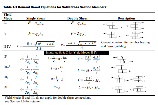
The equations are fairly complex, but it should be intuitive that the calculated fastener capacity decreases with increasing gap. Engineers are often surprised to see a 40, 50, even 60% drop in fastener capacity with one layer of 5/8” gypsum board. So what else can you do?
Testing, of course! In So, What’s Behind a Screw’s Allowable Load? I discussed the methods used to load rate a proprietary fastener such as the Simpson Strong-Tie® Strong-Drive® SDS or SDW screws. To recap, ICC-ES Acceptance Criteria for Alternate Dowel Type Fasteners, AC233, allows you to calculate and do verification tests, or load rate based on testing alone. We develop our allowable loads primarily by testing, as the performance enhancing features and material optimizations in our fasteners are not addressed by NDS equations.
So to determine the performance of a fastener installed through gypsum board, we tested the fastener through gypsum board. This is easier to do if you happen to have a test lab with a lot of wood and fasteners in it. We did have to run down to the local hardware store to pick up gypsum board for the testing.
A full set of allowable loads for Strong-Drive SDWH and SDWS are available on strongtie.com. The information is given as single fastener shear values for engineered design, and also screw spacing tables for common ledger configurations. As much fun as writing spreadsheets to do the Technical Report 12 calculations is, having tabulated values based on testing is much easier.
Fastening Systems
In the fastener marketplace, Simpson Strong-Tie stands apart from the rest. Quality and reliability is our top priority.

Pile Construction Fasteners – New and Expanded Applications
The majority of Simpson Strong-Tie fasteners are used to secure small, solid-sawn lumber and engineered wood members. However, there is a segment in the construction world where large piles are the norm. Pile framing is common in piers along the coast, elevated houses along the beach, and docks and boardwalks.
While the term “pile” is generic, the piles themselves are not generic. They come in both square and round shapes, as well as an array of sizes, and they vary greatly based on region. The most common pile sizes are 8 inches, 10 inches, and 12 inches, square and round, but they can be found in other sizes. The 8-inch and 10-inch round piles are usually supplied in their natural shape, while 12-inch round piles are often shaped to ensure a consistent diameter and straightness. All piles are preservative-treated.
Historically, the attachment of framing to piles has been done with bolts. This is a very labor-intensive method of construction, but for many years there was no viable fastener alternative. Two years ago, however, Simpson Strong-Tie introduced a new screw, the Strong-Drive® SDWH Timber-Hex HDG screw (SDWH27G), specifically designed for pile- framing construction needs. It can be installed without predrilling and is hot-dip galvanized (ASTM A153, Class C) for exterior applications.

Simpson Strong-Tie tested a number of different pile-framing connections that can be made with the SDWH27G screw. This blog post will highlight some of the tested connections. More information can be found in the following three documents on our website:
- The flier for the SDWH Timber-Hex HDG screw: F-FSDWHHDG14 found here.
- The engineering letter for Square Piles found here.
- The engineering letter for Round Piles found here.
The flier provides product information, and the engineering letters include dimensional details for common pile-framing connections that were tested.
Piles are typically notched or coped to receive a horizontal framing member called a “stringer.” The coped shoulder provides bearing for the stringer and serves as a means of transferring gravity load to the pile. The SDWH27G can be used to fasten framing to coped and non-coped round and square piles.
The connections that we tested can be put into four general groups that include both round and square piles:
- Two-side framing on coped and non-coped piles
- One–side framing on coped and non-coped piles
- Corner framing on coped piles
- Bracing connections
Additionally, the testing program included four different framing materials in several thicknesses and depths:
- Glulam
- Parallam
- Sawn lumber
- LSL/LVL
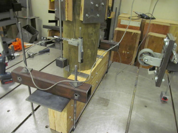
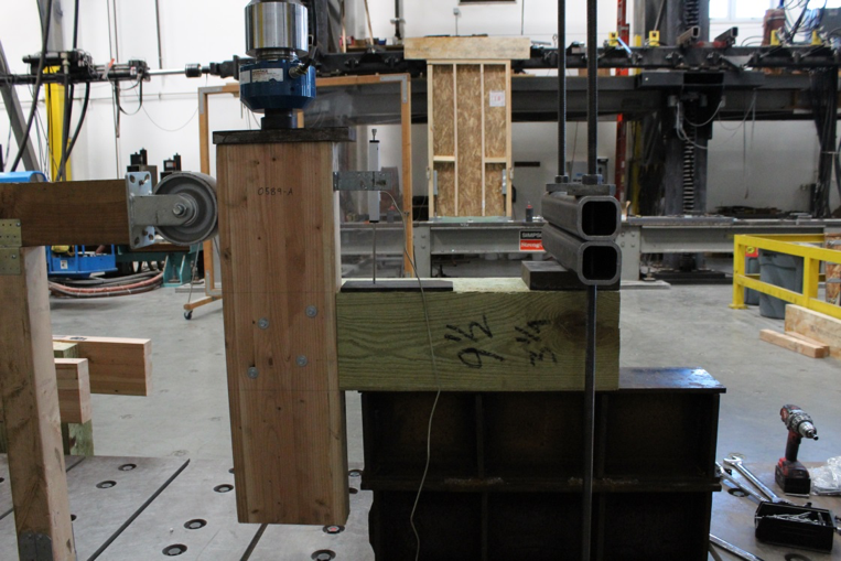
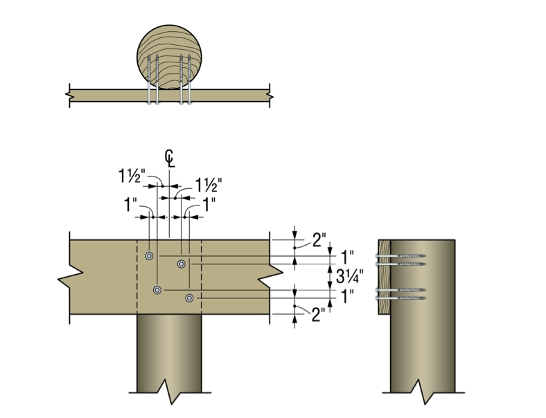
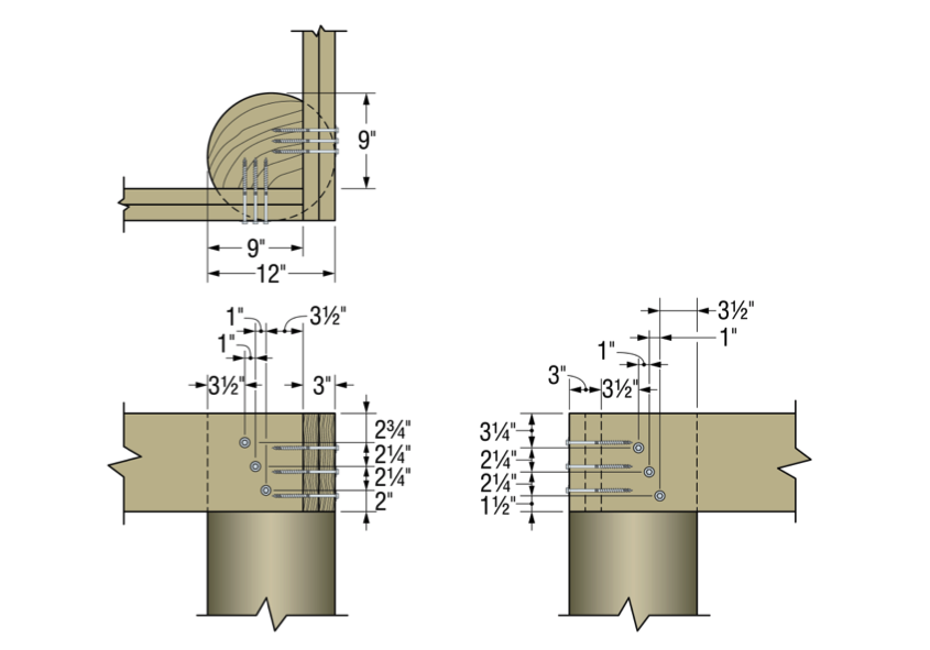
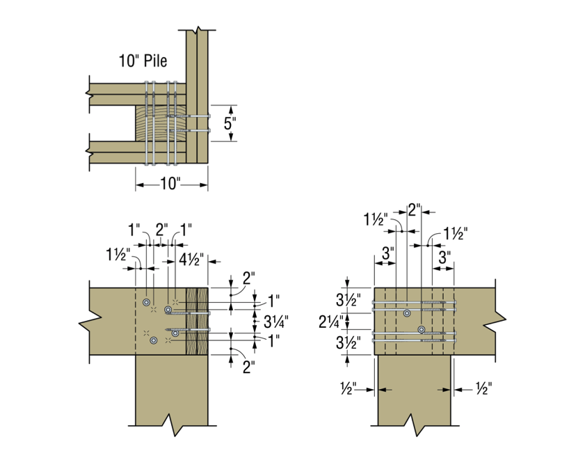
The total testing program included more than 50 connection conditions that represented pile shape and size, framing material and thickness and framing orientation and details. We assigned allowable uplift and lateral properties to the tested connections using the analysis methods of ICC-ES AC13. Figures 2 and 3 show some of the tested assemblies.
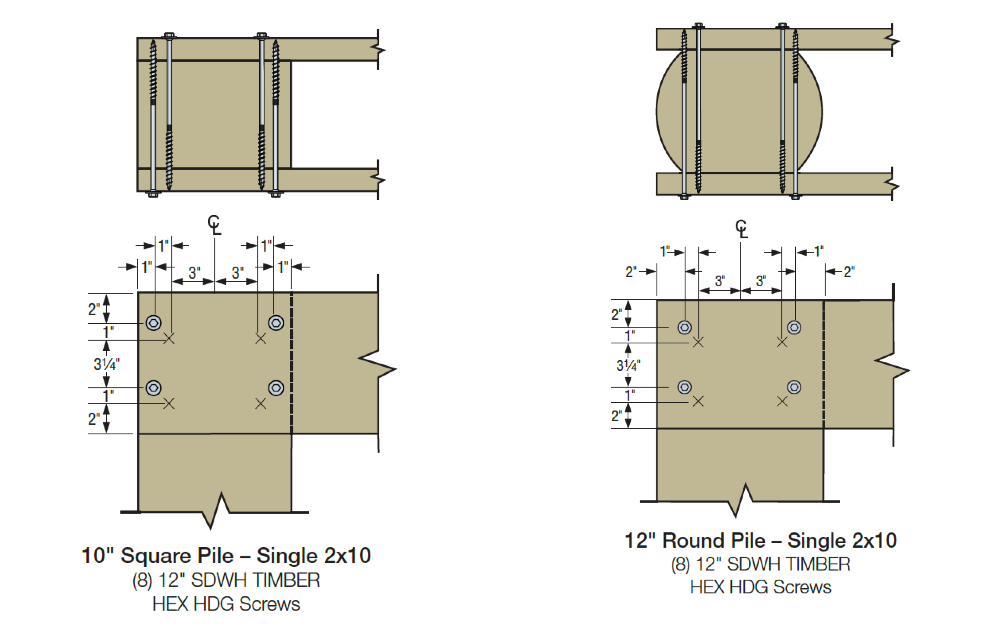
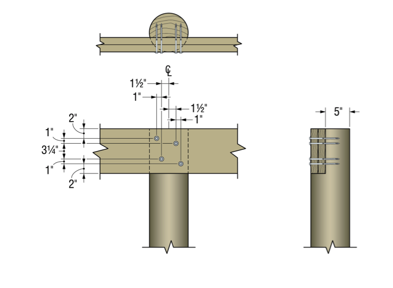
Figures 4 through 9 illustrate some of the connections and details that are presented in the flier and engineering letters.
Some elements of practice are important to the design of pile-framing connections. Some of the basic practices include:
- For coped connections, the coped section shall not be more than 50% of the cross-section.
- For coped connections, the coped shoulder should be as wide as the framing member(s).
- Fastener spacing is critical to the capacity of the connection.
- When installing fasteners from two directions, lay out the fasteners so that they do not intersect.
In many cases, pile-framing connections use angled braces for extra lateral support. The SDWH27G can be used in these cases too.

In the flier and engineering letters previously referenced, you will find allowable loads and specific fastener specifications for many combinations of stringer and pile types and sizes.
What have you seen in your area? Let us know – perhaps we can add your conditions to our list.
How to Pick a Connector Series – Selecting Fasteners
The parts won’t hold themselves up. They have to be fastened in place.
The previous blog in the How to Pick a Connector Series by Randy Shackelford, on “ Selecting a Joist Hanger,” covered the available Simpson Strong-Tie joist hanger options and how to pick a hanger for your design. This week’s blog focuses on the fasteners recommended for various wood connectors.
For straps, holdowns and other connectors, the first step is to specify a product that meets the load and corrosion resistance requirements. Then, specify fastening that is appropriate. The Wood Construction Connectors catalog, C-C-2026, offers fastener information for every Simpson Strong-Tie connector used in wood construction. If you specify the type and number of fasteners and install them as shown in the catalog, then your installation will get full design values. Many connectors are designed to be installed with either nails or Strong-Drive® SD Connector screws. Some products must be installed with Strong-Drive SDS Heavy-Duty Connector screws. Figure 1 is a snip from page 114 of catalog C-C-2026. Here the face-mount hanger table gives the size and number of nails to be installed in the header and the joist, and the table note defines the nail size terminology. Let’s take a look at the various fasteners used for Simpson Strong-Tie connectors of all varieties.
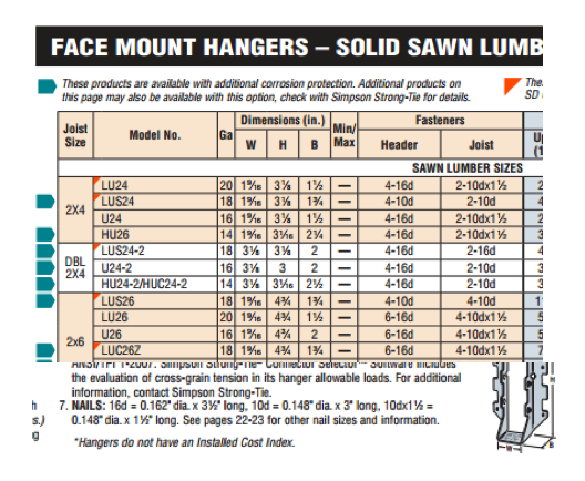
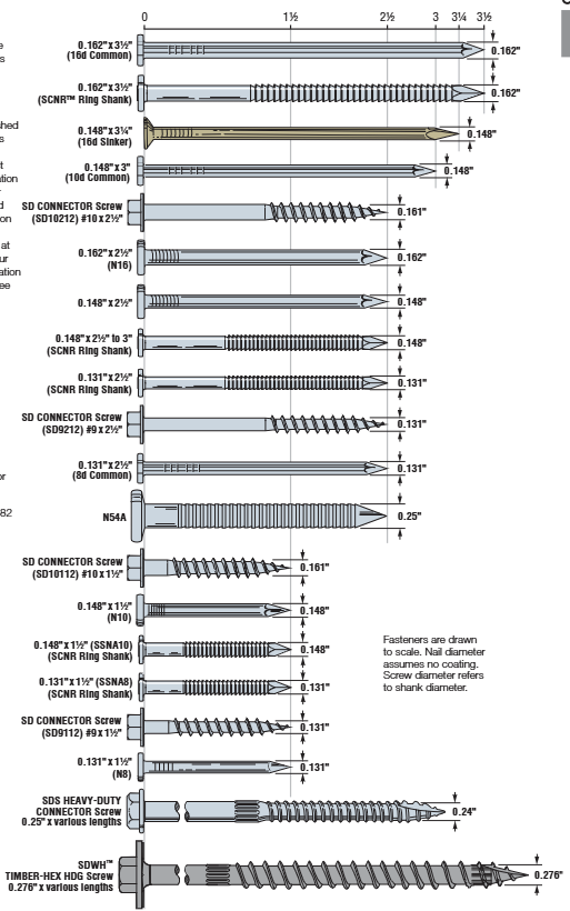
Figure 2 shows a scale view of almost all of the fasteners used with connectors. You can find this illustration in the Fastening Systems catalog, C-F-2025, and the Wood Construction Connectors catalog, C-C-2026. However, we are continually designing, evaluating and adding new fasteners to use with our connectors. Check our website for the latest and greatest.
Keep in mind some generalities that are to be considered in every connector fastener specification.
- Type and size – Be sure to specify the correct type of fastener and size; for nails, that means diameter and length.
- Do not mix fasteners – Do not combine nails and screws in the same connector unless specifically allowed to do so in the load table.
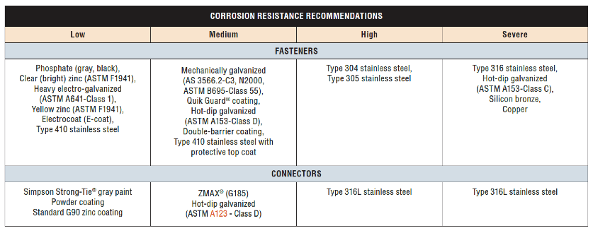
- Corrosion resistance – Consider environmental corrosion and galvanic corrosion. For environmental corrosion, specify fasteners that have corrosion resistance similar to the connector; for galvanic corrosion, the fasteners and connector should be galvanically compatible. Figure 3 shows the corrosion resistance recommendations for fasteners and connectors.
NAILS
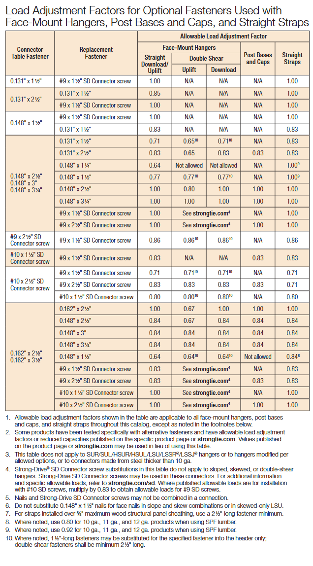
Nail terminology is messy. In a Structure Magazine article (July 2016), the author made the point that nail specifications are frequently misinterpreted (or overlooked), and as a result the built system does not have the intended design capacity. In general construction vernacular, specification by penny size identifies only the length. For example, a “10d” specification could be interpreted to mean 10d common – 0.148″ x 3″, 10d box – 0.128″ x 3″, 10d sinker – 0.120″ x 2.875″, or the 10d x 2.5″ – 0.148″ x 2.5″. See NDS-24, Appendix L, Table L4 for the length, nail diameter and head diameter of Common, Box, and Sinker steel wire nails. What if the face-mount hanger needed 0.148”x3” nails to achieve full load, but the face-mount hanger was installed with 0.148″ x2.5″? In this case, the nail substitution causes a reduction in load capacity of 15%. The load capacity losses would be even greater if 10d sinker or 10d box nails were used. The load adjustment factors for nail substitutions used with face- mount hangers and straight straps are shown in Table 3.
Simpson Strong-Tie nail terminology further complicates nail specification because, in Strong-Tie lingo, the penny reference is to diameter (not to length). This is further reason to write nail specifications in terms of diameter and length.
The best way to prevent mistakes is to specify nails by both length AND diameter.
There are two types of connector nails available, the Strong-Drive® SCNR Ring-Shank Connector nail and the Strong-Drive SCN Smooth-Shank Connector nail. SCN stands for Structural Connector Nails. R would refer to ring- shank nails. Currently most ring-shank connector nails are available in Type 316 stainless steel. Reasons for this are discussed here. The smooth-shank nails are made of carbon steel and either have a hot-dip galvanized (HDG) finish meeting the specifications of ASTM A153, Class D, or have a bright finish. Stainless-steel ring-shank nails are recommended for stainless-steel connectors. Use hot-dip galvanized nails with ZMAX® and HDG connectors. See Load tables for the nail properties.
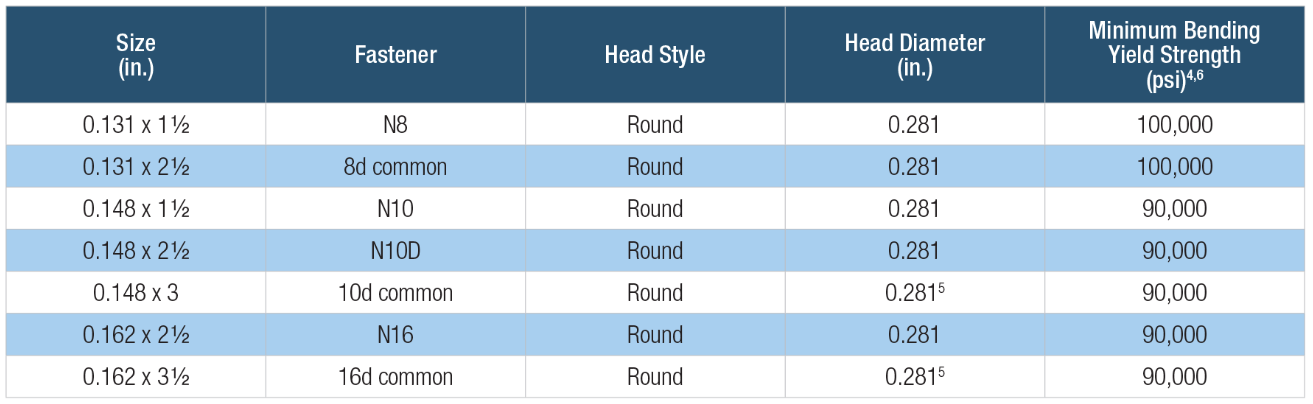
Simpson Strong-Tie connector nail specifications include common nails, sinker nails and short nails. Nails used in connectors should always have a full round head and meet the bending yield requirements of ASTM F1667, Table S1. Nails can be driven with a hammer or power-driven. Table 2 shows the Strong-Tie connector nails by catalog name, size and model number.

Remember that connector double-shear nailing should always use full-length common nails. Do not use shorter nails in double-shear conditions.
Table 3 is snipped from the Fastening Systems catalog, and it shows load adjustment factors for optional fasteners used in face-mount hangers and straps.
SD Screws
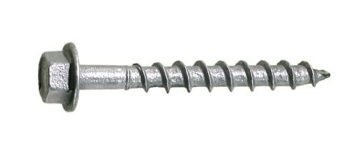
Almost 150 Simpson Strong-Tie connectors can be installed with Simpson Strong-Tie Strong-Drive® SD Connector screws (Figure 4). The shanks of the SD Connector screws are designed to match the fastener holes in Simpson Strong-tie connectors. The screw features, dimensions, strengths and allowable single-fastener properties are given in ICC-ES ESR-3046, and the SD screws have been qualified for use in engineered wood products. See ICC-ES ESR-3096 for code-approved connectors installed with SD screws.
SD screws can make connector and strap installation easier and can also provide some resistance that is needed beyond what might be offered by nails. Ease of installation is sometimes an issue in tight places where it might be much easier to use a screw-driving tool rather than a hammer or a power nailer. Some installations are improved by using screws instead of nails, especially where pulling away from the mounting member is a possible failure mode. For example, joist hangers for a deck need withdrawal resistance to help keep the deck tightly connected to the ledger.
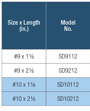
SD screws are available in four sizes as shown in Table 4 below. These screws are mechanically galvanized per ASTM B695, Class 55, and have corrosion-resistance qualifications for use in chemically treated wood for Exposure Conditions 1 and 3 per ICC-ES AC257, which is the acceptance criterion for Corrosion-Resistant Fasteners and Evaluation of Corrosion Effects of Wood Treatment Chemicals. See ICC-ES ESR-3046 for corrosion resistance details. Visit SD Screws in Connectors for a complete list of connectors that can be installed with SD screws.
Here are a few specification and construction tips for SD screws:
- SD10 screws replace 16d common and N16 nails in face-mount hangers and straps.
- SD9 screws replace 8d and 10d common and 1-1/2″ size nails and 16d sinker nails (all nails 0.148″ and 0.131″ diameter) in face-mount hangers and straps.
- When SD screws are to be an alternative to nails, specify and use only SD screws. Other types of screws shall not be substituted.
- SD screws are required to be installed by turning. Do not drive them with a hammer or palm nailer!
- SD screws and nails cannot be mixed in the same connector.
SDS Screws
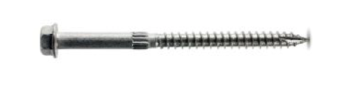
The Simpson Strong-Tie Strong Drive® SDS Heavy-Duty Connector screws are 1/4″ screws with a hex washer head (Figure 5). They are available in nine lengths. Table 5 shows the available SDS screws. SDS Screws are available with a double-barrier coating or in Type 316 stainless steel. These screws can be installed with no predrilling and have been extensively tested in various applications. SDS screws can be used for both interior and exterior applications. See ICC-ES ESR-2236 for dimensions, mechanical properties and single-fastener allowable properties. As shown in the evaluation report, SDS screws are also qualified for use in chemically treated wood. See the evaluation report for particulars. SDS screws also have been qualified for use in engineered wood products.
If you need more information about the nails and screws recommended for use with Simpson Strong-Tie connectors, visit strongtie.com and see the appropriate catalog, flier or engineering letter. Remember, your choice of fasteners affects the load capacity of your connections.
Let us know if you have any comments on Simpson Strong-Tie fasteners for straps, holdowns and other connectors.
Pier Decking Fasteners
This week’s post is a case study featuring a recent restoration job on the central coast of California and how Simpson Strong-Tie® hot-dipped galvanized screws proved to be a better option than traditional spikes.
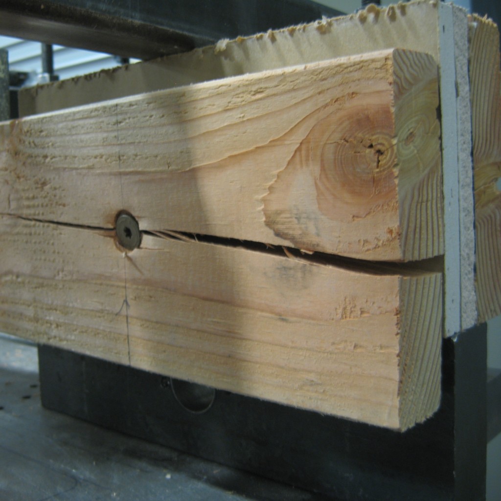
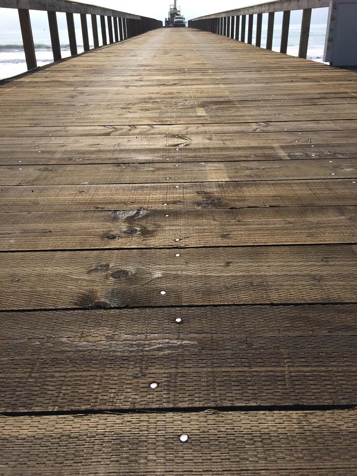
A pier originally constructed in the 1800s was closed a few years ago as general deterioration caused the structure to become unsafe. As preparation for rebuilding the pier began, one of the major concerns was the attachment of the deck boards to the framing.
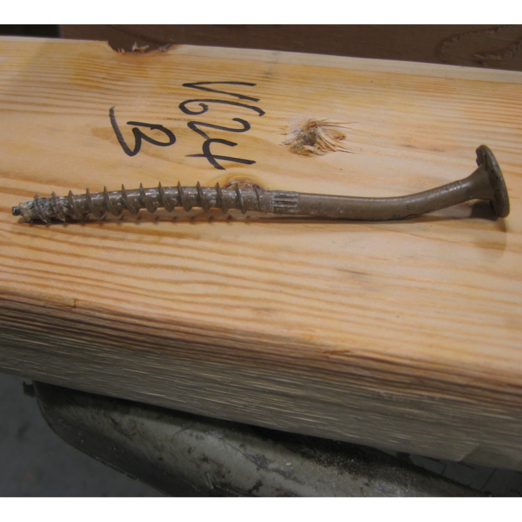
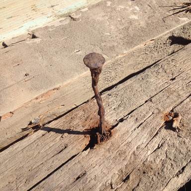
Traditionally, the deck boards have been attached with hot-dip galvanized 60d (0.283″ x 6″) spikes. However, spikes have a low withdrawal resistance, are typically predrilled and have a multi-step installation process. In addition, spikes, over time, can begin to back out so that the heads protrude above the top of the deck boards. This creates an unsafe condition for pedestrians and also results in ongoing maintenance work. Here you can see one of the old spikes.
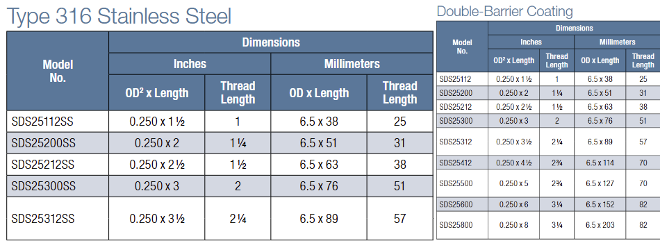
Simpson Strong-Tie provided two options for replacing these spikes: the Strong-Drive® Timber-Hex HDG screw, SDWH27800G, and its stainless-steel counterpart, the Strong-Drive Timber-Hex SS screw, SDWH27800SS. The SDWH27800G screw measures 0.276″ x 8″ and has a hot-dip galvanized coating, conforming to ASTM A153 Class-C. The SDWH27800SS screw measures 0.276″ x 8″ and is made from Type 316 stainless steel. Both of these screws have integral washer, hex-drive heads and are self-drilling. They are not intended to be self-countersinking though, and as a result, installation with the heads below the deck surface requires a shallow dapped hole.
A comparison of the load values was provided to Shoreline Engineering, Inc. engineers Bruce S. Elster, P.E., and Jonathan T. Boynton, P.E., for their review and approval. In addition, Simpson Strong-Tie Fastening Systems/Dealer Sales Representative Darwin Waite expertly conducted on-site demonstrations for numerous decision makers including the contractor and city officials. These demonstrations allowed the contractor and owners to compare the labor costs and finished appearance of the different fastening methods.

Below is a comparison of the allowable load values* of the potential fasteners. We can see how each of the Simpson Strong-Tie screw options exceeds the spike load values in all load conditions.

*Not to be used for design purposes as footnotes have been left out of this blog post. Table values include wet service factor adjustments.
In the end, the SDWH27800SS stainless-steel screw was specified for the project.
Some might consider a 316 stainless steel screw to be cost prohibitive, but when you factor in the lower cost of installation, the lower maintenance requirements and the actual cost of the fastener, this screw turned out to be the lowest cost alternate. In addition, it provided better withdrawal and lateral load values than the spikes.

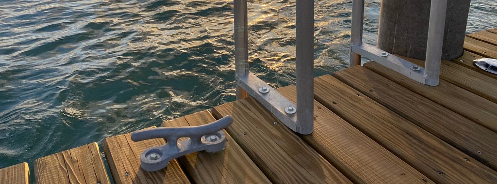
The Strong-Drive Timber-Hex SS screws made it possible to complete the deck restoration on time and on budget. Perhaps just as importantly, the pier looks beautiful and should last for many years to come.
Let us know if the comments below if you have any questions about specifying these fasteners for securing decks, docks, pilings and other heavy-duty, coastal applications.
As always, call our Engineering Department if you have any questions.
Have you used the SDWH27800SS screw for a project? Tell us about in the comments below.

Deck Fasteners – Deck Board to Framing Attachments
When you’re building a deck, it’s important to know the types of fasteners you need to use with the various materials that are available. On this week’s post we explore some deck fastener applications as well as offer suggestions on how to avoid a few common problems. We will address two generic types of deck boards fastened to wood framing: preservative-treated wood and composite decking.
Preservative-Treated Wood Decking
With preservative treated wood, it pays to know the board treatment. Wood is treated with a water-borne treatment chemical (typically micronized copper azole these days) and then it is either sent out wet or it is kiln dried. Wet-treated wood can have a moisture content (MC) greater than 30%. Wood that is subsequently kiln dried to remove excess moisture after the treatment process is labeled Kiln-Dried After Treatment (KDAT) and has a MC of about 15%. Wood deck boards with preservative treatments will be labeled as such regardless of their moisture condition.
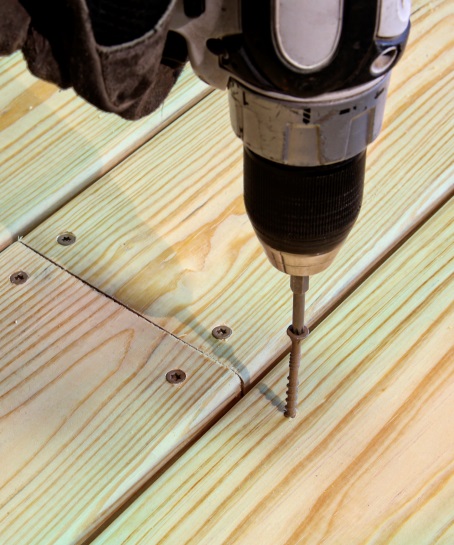
The moisture condition of the deck boards determines how best to fasten and space your deck boards. Wet wood will shrink in width and thickness after installation. As a result, you should install these boards butted tight so that gaps will emerge after they dry in place. On the other hand, KDAT wood or wood that is dry should be installed with 1/8” gaps between boards so there is a slight gap after the boards get wet and swell due to rain, ice and snow. Some manufacturers suggest using an 8d common nail for spacing when installing KDAT decking, as seen in the figure below.
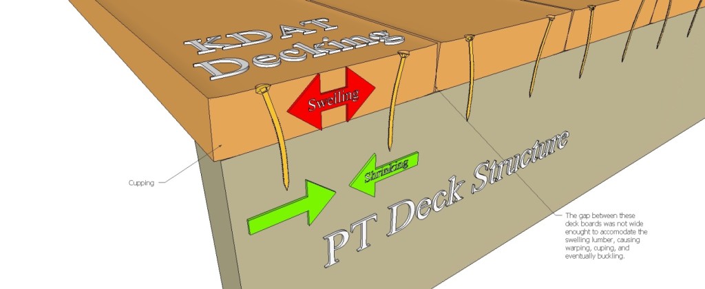
Shrinking and swelling of any installed deck board can cause the deck fastener to bend back and forth with the MC cycling. This causes many deck fasteners to break because of the fatigue loading, which can be exacerbated by the brittle steel used in most deck screws.
To combat this problem, Simpson Strong-Tie developed the DSV Wood screw. This screw is specifically designed with increased ductility to handle the bending induced by deck board movement. It is available in a variety of lengths with threads optimized to prevent jacking between the deck board and the framing, ensuring a snug long-lasting connection.
Composite deck boards are made from a mixture of wood fiber and plastic or are entirely “plastic.” Wood plastic composites and plastic materials exhibit thermal expansion, so they expand and contract in thickness, width and length as a function of temperature and solar heating. Consequently, they typically require a special screw designed for composite decking. Screws for this application will often utilize a two-thread design. The lower thread drives the screw into the framing while the upper thread pulls the loosened composite material back into the hole and holds the deck board tight to the joist. Composite screws also have a cap-style head that covers any residual material left around the screw body and leaves a clean finish. Ductility is important to these screws too.
Given the wide variety of composite deck producers, we designed a screw that works well with all of them. The DCU screw works in all types of composite decking fastened to wood framing.
A note about cellular PVC deck boards: the manufacturers’ recommendation of stainless-steel screws restricts the use of many deck board fasteners. Be sure to read and follow the decking material fastener requirements. Simpson Strong-Tie has a broad offering of painted stainless-steel deck screws available to match PVC deck boards. Find the proper match for your board here.
For other deck fastener applications, including decking fastened to steel framing, and information about other deck fasteners available, see our website product page.
Are there other applications that you want to know about that we didn’t share here? Let us know in the comments below. As always, call us in the Engineering Department if you have questions.

Testing Fasteners for Deck Ledger Connections
This week’s blog post was written by Aram Khachadourian, R&D Engineer for Fastening Systems. Since joining Simpson Strong-Tie 14 years ago, he has designed and tested holdowns, hangers, truss connectors and anchor bolts. He has drafted numerous acceptance criteria as well as quality standards. His current focus is the development, testing and code approval of structural fasteners. Prior to his work at Simpson Strong-Tie, he spent his time designing steel buildings including strip malls, wineries and airplane hangars. Aram graduated from the University of California at Davis with a Civil Engineering degree, and is a registered professional engineer in California.
As we approach the beginning of spring, homeowners across the country are starting to turn their thoughts to the backyard and making plans to add a new deck for summer enjoyment.
As a contractor, designer, or homeowner, you want to know that this new deck will have the structural integrity to stand firm for many years and remain safe for everybody who will use it. While there are many aspects to building a safe, strong deck, today we are focusing on the attachment of the deck ledger to the structure.
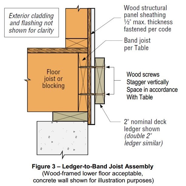
Prior to 2009, numerous catastrophic deck failures attributed to improper deck ledger attachments demonstrated the need for building code guidance. A calculated solution was overly conservative because the sheathing layer, typically present between the deck ledger and the structure’s band joist, was considered to be a gap in the connection. A prescriptive approach to deck ledger attachments was finally introduced in the 2009 International Residential Code (IRC). Table R502.2.2.1 provided fastener spacings for ½”-diameter lag screws and bolts. These values were based on testing conducted by researchers at Virginia Tech and Washington State University.
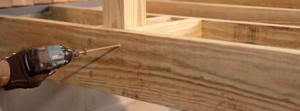
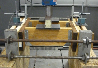
The tests included a variety of band joist types, with pressure-treated Hem-Fir as the deck ledger material. The deck ledger was tested at high moisture content to represent a wet, worst-case field condition. The test assembly had a load bar spanning two joists that were attached to the deck ledger with joist hangers. The ledger was attached through the sheathing to the rim board. Only the rim board was supported by the test frame. The average ultimate load was divided by a factor-of-safety of 3 and then further divided by the load duration coefficient of 1.6 to achieve an allowable load. These values were then applied to a deck live load of 40 psf plus a deck dead load of 10 psf to derive allowable fastener on-center spacings for various joist spans.
When Simpson Strong-Tie began to rate fasteners for ledger connections, we used a similar method of testing and analysis. However, we incorporated a few changes. One of the changes we implemented was a symmetric test set-up. The original test assembly had a ledger on one end of the joists and a support member as the boundary condition on the other. We put a ledger at each end of the joists so stiffness differences in the supports would not affect the test results. We also chose a larger factor-of-safety of 3.2 (instead of 3.0) to maintain consistency with calculation of fastener allowable loads in other applications. In order to provide our customers with a broader range of construction options, we tested many typical rim board and ledger materials, and we ran tests with single and double ledgers. You can see an example of a typical test set up here:
We have tested many Simpson Strong-Tie® Strong-Drive® fasteners for ledger applications including the SDWS Timber screw (SDWS22DB), SDWH Timber-Hex SS screw (SDWH-SS), SDWH Timber-Hex screw (SDWH19DB), and SDS Heavy-Duty Connector screw (SDS). We also have information regarding ledgers attached to studs and ledgers fastened over gypsum board. You can find all of this information in our latest fastener catalog.
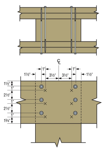
One final construction tip – deck ledgers can fail due to cross-grain tension. This occurs when the joist hangers are attached to the deck ledger near the bottom of the ledger, but the fasteners holding the ledger to the building are near the top of the ledger. To prevent cross-grain tension failure, place the joist hangers so at least half of the ledger fasteners are below the joist hanger line.
Take a look through the various ledger options in our fastener catalog, and if we don’t address your condition, let us know. As always, call us in the Engineering Department if you have questions.
Please share your feedback in the comments area below.

Don’t Get Washed Away – The Next Wave of Pile Fastener Innovation Has Arrived
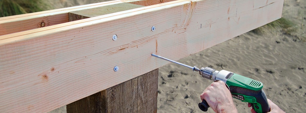
For decades, bolts were used for pile construction to ensure a structurally sound connection. While this works on paper, these types of bolted connections are not user friendly to install in the field. The more difficult the connection is to make, the more likely it won’t be done right.
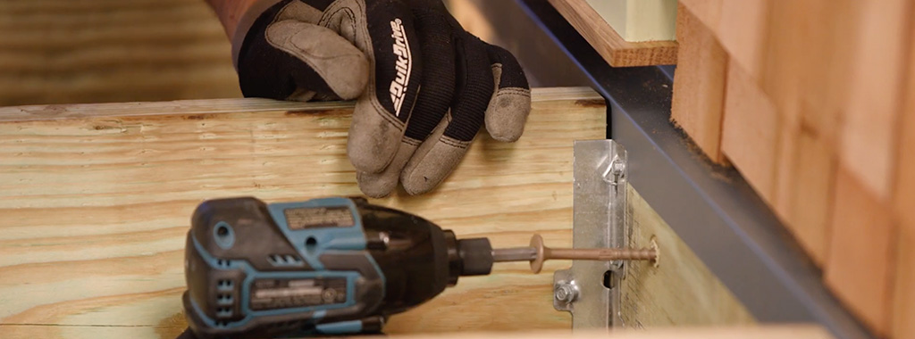
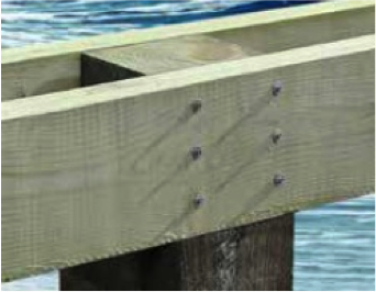
Many pile connections have stringers or beams on each side of the pile. This means the predrilled hole for the bolt must be properly aligned through all of the parts. It takes considerable strength and the skill and care of a craftsman to do this properly, often from the top of a ladder. Given the large size of many piles, the installer also has to tighten the bolt while blind to the back of the assembly. It can take a few minutes per fastener to get the job done right. These conditions have created a great need in the field for a better approach.

After much design and testing, Simpson Strong-Tie has come out with a new faster and safer solution, the SDWH Timber-Hex HDG screw. The screw has a special point, so no predrilling is required. The installation of this fastener takes a matter of seconds, not minutes. This adds up to hours of saved labor costs.
More information about the SDWH Timber-Hex HDG screw can be found in the newly released flier F-F-SDWHHDG24, which is on our website.
Loads for these screws are presented two ways. First, there are individual fastener connection values based on screw length and wood side-plate thickness. Second, loads are given for entire assembly connections. These loads are based on the testing of specific fastener layouts. Our assembly testing used piles with one or two stringers attached to each side of the pile. Here is an example of a load table for stringer-to-square pile connection loads.

Connection assembly layouts are shown in the F-F-SDWHHDG24 flier for square piles, round piles, piles with continuous stringers and piles with stringers that are spliced at the pile. Here is one example below:
We are testing additional assemblies as other connections, materials and conditions are identified.
If you have a common condition that you don’t see addressed in the flier, please let us know in the comments below. You can also always call us in the Engineering Department if you have questions.