


While stick-frame roofs are sometimes preferred to premanufactured roof trusses in some areas of the country because they can accommodate larger attics, higher ceilings, and complex roof shapes, the code requirements for these roofs are often more complex. That’s largely because, unlike truss-framed roofs, the code needs to provide a complete prescriptive method of building the roof, including the multitude of connections that must be made in the field. And, to complicate matters further, the code requirements for stick-frame roofing have been rewritten in each of the last two code cycles. I’d like to give you a high-level overview of some of those changes. In a previous SE Blog post, we discussed the design concepts of stick-framed roofs, and summarized a few of the solutions offered by the Simpson Strong-Tie® connector system for stick-frame roofing. The main concept in that post was the necessity of a continuous tie across the bottom of the rafter system to prevent the heels of the rafters from spreading under load and pushing out on the tops of the walls.
Tag: awc

Keep Your Roof On
He huffed, and he puffed, and he blew the roof sheathing off! That’s not the way kids’ tale goes, but the dangers high winds pose to roof sheathing are very real. Once the roof sheathing is gone, the structure is open and its contents are exposed to the elements and much more vulnerable to wind or water damage. It is a storyline that we meet all too often in the news.
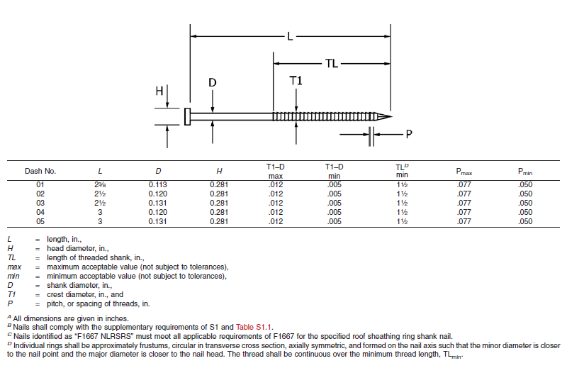
About two years ago, the ASTM subcommittee on Driven and Other Fasteners (F16.05), addressed fastening for roof sheathing in high-wind areas by adding a special nail to ASTM F1667-17 – Standard Specification for Driven Fasteners: Nails, Spikes and Staples. The Roof Sheathing Ring-Shank Nail was added to the standard as Table 46. Figure 1 illustrates the nail and lists its geometrical specifications. This is a family of five ring-shank nails that can be made from carbon steel or stainless steel (300 series). Specific features of these nails are the ring pitch (number of rings per inch), the ring diameter over the shank, the length of deformed shank and the head diameter. Also, note B specifies that the nails shall comply with the supplementary requirement of Table S1.1, which tabulates bending yield strength. In this diameter class, the minimum bending yield strength allowed is 100 ksi.
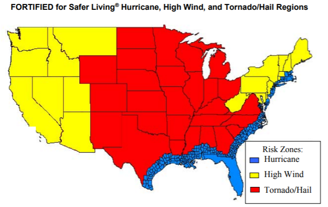
The IBHS (Insurance Institute for Business and Home Safety) discusses roof deck fastening in its Builders Guide that describes the “FORTIFIED for Safer Living” structures. The IBHS FORTIFIED program offers solutions that reduce building vulnerability to severe thunderstorms, hurricanes and tornadoes. Keeping the roof sheathing on the structure is critical to maintaining a safe enclosure and minimizing damage, and roof sheathing ring-shank nails can be part of the solution. As Figure 2 from IBHS (2008) shows, every wood-frame structure has wind vulnerability.
More importantly for the wood-frame engineering community, the Roof Sheathing Ring-Shank Nails are being included in the next revision of the AWC National Design Specification for Wood Construction (NDS-2018), which is a reference document to both the International Building Code and the International Residential Code. You will be able to use the same NDS-2018, chapter 12 withdrawal equation to calculate the withdrawal resistance for Roof Sheathing Ring-Shank Nails and Post Frame Ring-Shank nails. The calculated withdrawal will be based on the length of deformed shank embedded in the framing member. Also, Designers need to consider the risk of nail head pull-through when fastening roof sheathing with ring-shank nails. If the pull-through for roof sheathing ring-shank nails is not published, you will be able to use the new pull-through equation in the NDS-2018 to estimate that resistance.
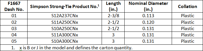
Simpson Strong-Tie has some stainless-steel products that meet the requirements for Roof Sheathing Ring-Shank Nails. These will be especially important to those in coastal high-wind areas. Table 1 shows some of the Simpson Strong-Tie nails that can be used as roof sheathing ring-shank nails. These nails meet the geometry and bending yield strength requirements given in ASTM F1667. See the Fastening Systems catalog C-F-2017 for nails in Type 316 stainless steel that also comply with the standard.
Improve your disaster resilience and withstand extreme winds by fastening the sheathing with roof sheathing ring-shank nails. You can find Roof Sheathing Ring-Shank nails in ASTM F1667, Table 46, and you will see them in the AWC NDS-2018, which will be available at the end of the year. Let us know your preferred fastening practices for roof sheathing.

Revisiting Spanning the Gap

Three years ago, we created this blog post based on a technical support question we often receive about allowable fastener loads for ledgers to wood framing over gypsum board. Given that this is still a frequent question and a relevant topic, we decided to revisit the post and update it.
Drywall. Wall board. Sheetrock. Sackett Board? A product called Sackett Board was invented in the 1890s, which was made by plastering within wool felt paper. United States Gypsum Corporation refined Sackett Board for several years until 1916, when they developed a new method of producing boards with a single layer of plaster and paper. This innovation was eventually branded SHEETROCK®. More details about the history of USG can be found here.
No matter what you call it, gypsum board is found in almost every type of construction. Architects use it for sound and fire ratings, while structural engineers need to account for its weight in our load calculations. A common technical support question we receive is for allowable fastener loads for ledgers to wood framing over gypsum board.
One method to evaluate a fastener spanning across gypsum board is to treat the gypsum material as an air gap. Technical Report 12, General Dowel Equations for Calculating Lateral Connection Values, is published by the American Wood Council.

TR12 has yield limit equations that allow a designer to account for a gap between the main member and side member of a connection. With a gap of zero (g=0), the TR12 equations provide the same results as the NDS yield limit equations.
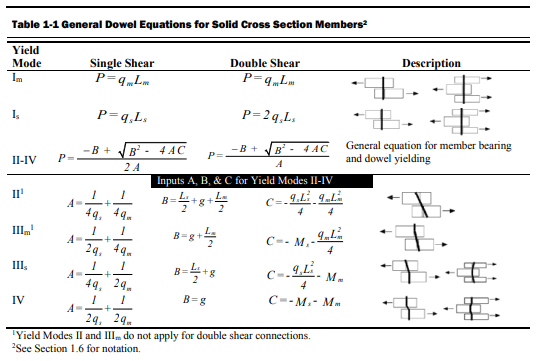
The equations are fairly complex, but it should be intuitive that the calculated fastener capacity decreases with increasing gap. Engineers are often surprised to see a 40, 50, even 60% drop in fastener capacity with one layer of 5/8” gypsum board. So what else can you do?
Testing, of course! In So, What’s Behind a Screw’s Allowable Load? I discussed the methods used to load rate a proprietary fastener such as the Simpson Strong-Tie® Strong-Drive® SDS or SDW screws. To recap, ICC-ES Acceptance Criteria for Alternate Dowel Type Fasteners, AC233, allows you to calculate and do verification tests, or load rate based on testing alone. We develop our allowable loads primarily by testing, as the performance enhancing features and material optimizations in our fasteners are not addressed by NDS equations.
So to determine the performance of a fastener installed through gypsum board, we tested the fastener through gypsum board. This is easier to do if you happen to have a test lab with a lot of wood and fasteners in it. We did have to run down to the local hardware store to pick up gypsum board for the testing.
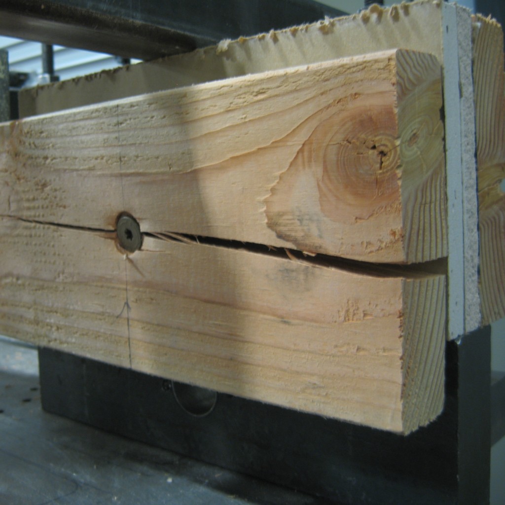
A full set of allowable loads for Strong-Drive SDWH and SDWS are available on strongtie.com. The information is given as single fastener shear values for engineered design, and also screw spacing tables for common ledger configurations. As much fun as writing spreadsheets to do the Technical Report 12 calculations is, having tabulated values based on testing is much easier.
Fastening Systems
In the fastener marketplace, Simpson Strong-Tie stands apart from the rest. Quality and reliability is our top priority.

Mass Timber Construction – Building for the Future
The future is here and that future is mass timber construction.
It is common knowledge that wood is a renewable and environmentally friendly building material. There are two types of wood-framing methods in North America. The most common method for residential construction is light-frame construction using either balloon-framing or platform-framing methods. Standardized dimensional lumber has become the dominant building material in light-frame construction because of its economy. The other method is heavy-timber construction, which often uses large solid-wood sections for nonresidential construction, such as for storage, mercantile and industrial buildings.
In Europe, there is a trend to create larger “laminated” wood sections using the more traditional standardized dimensional lumber of the 1990s. This trend culminated in what is now classified as cross-laminated timber, or CLT. CLT can be used to create floor panels and roof panels. In North America, this is classified either as cross-laminated timber (CLT) or generically as mass timber.
CLT is essentially multiple layers of wood panels. Each layer of wooden panels is laid crosswise on the one before at approximately a 90° angle and glued using a polyurethane adhesive to increase the stability of the entire panel. Typical thickness of the individual boards can vary from 3/8″ to 2″ thick. Typical board width can vary from 2-3/8” to 9-1/2” wide. CLT panels are fabricated and marketed from 3-ply CLT up to 7-ply CLT. CLT 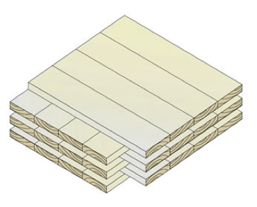 manufacturers normally publish characteristic properties for their panels – such as bending strength, shear strength, modulus of elasticity and panel stiffness – to assist Designers in specifying these products.
A Cross Laminated Timber Handbook has been published by FPInnovations in Canada as an introduction to CLT. The US edition CLT handbook can be downloaded for free here.
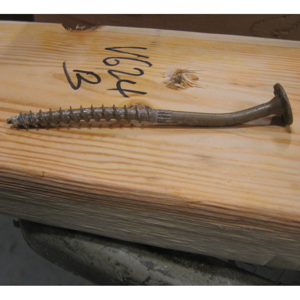
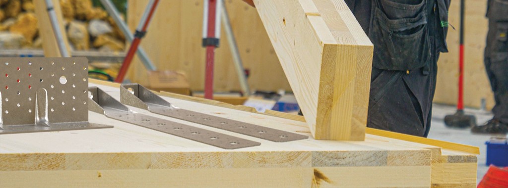
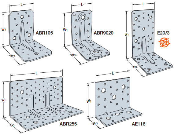
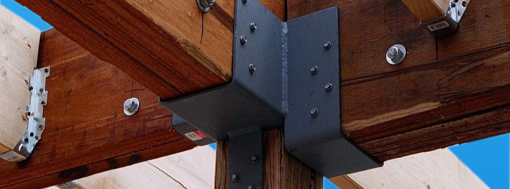
As in all wood buildings, connection designs are critical to the success of this new type of building material. Simpson Strong-Tie offices in Europe have been instrumental in developing and supplying connectors and fasteners in the CLT market. Simpson Strong-Tie has developed many connectors specifically for the CLT market in Europe (Figure 3).
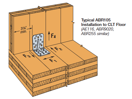
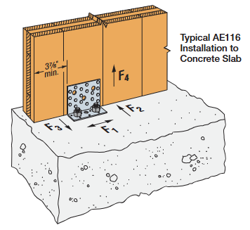
Those connectors are used to join the CLT floor panels to CLT wall panels and CLT wall panels to the concrete foundation (Figures 1 and 2).
 Specialized ring-shank nails and long metal screws have been developed as well. In mid-2014, Simpson Strong-Tie North America (Pleasanton, California Testing Facility) embarked on an initial test program to assess those connectors and fasteners developed for the CLT market by Simpson Strong-Tie Europe, using North American CLT panels to verify and quantify the performance characteristics according to North American testing protocols (American Society for Testing and Materials and Canadian Construction Materials Centre).
The initial test program used CLT panels fabricated in Western Canada using Canadian Spruce-Pine-Fir (S-P-F) lumber. The connectors and ring-shank nails were imported from the Simpson Strong-Tie European manufacturing facilities. Testing of the connectors also included the Simpson Strong-Tie Strong-Drive® SD screws, which as expected, provided higher load capacity than the ring-shank nails. A summary of the test program and the load rating developed for both the Canadian and the U.S. market can be downloaded here.
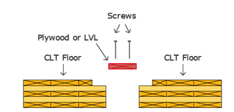
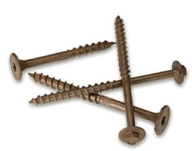
Other types of long countersunk screws such as the Strong-Drive® SDWS Timber screw (countersunk) or Strong-Drive SDWH Timber-Hex (hex head) screw (shown) are used either to splice the floor panels together or to drag the diaphragm loads back to the column or post as necessary.
As CLT continues to gain acceptance in North America, other connection details will also become more popular. Simpson Strong-Tie intends to continue developing and improving connection details to support this type of construction.
Building code acceptance is another important requirement and development that is in progress in both Canada and the U.S. In Canada, the 2014 edition of CSA O86 “Engineering Design in Wood” has reserved a section for CLT.
The 2015 edition of the International Building Code (IBC) recognized CLT when it is manufactured to the product standard. CLT walls and floors will be permitted in all types of combustible construction. The 2015 National Design Specification (NDS) for Wood Construction was recently published and approved as an ANSI American National Standard. The 2015 National Design Specification is also referenced in the 2015 IBC.
The future is here. Environmentally friendly mass timber (including CLT) is poised to grow in use, especially with the recognition of CLT in the building codes. North American manufacturing of CLT has been established and can only grow to support the expanding use of this new building material.
References:
https://fpinnovations.ca
*Images with permission from FPInnovations

New Treatment of Shear Wall Aspect Ratios in the 2015 SDPWS
This post was co-written by Simpson Engineer Randy Shackelford and AWC Engineer Phil Line.
The 2015 International Building Code references a newly updated 2015 Edition of the American Wood Council Special Design Provisions for Wind and Seismic standard (SDPWS). The updated SDPWS contains new provisions for design of high aspect ratio shear walls. For wood structural panels shear walls, the term high aspect ratio is considered to apply to walls with an aspect ratio greater than 2:1. These same high‑aspect‑ratio shear wall provisions have been maintained in subsequent editions of SDPWS, including the 2021 SDPWS, and remain part of current design practice.

In the 2015 SDPWS, reduction factors for high aspect ratio shear walls are no longer contained in the footnotes to Table 4.3.4 (See Figure 2). Instead, these factors are included in new provisions accounting for the reduced strength and stiffness of high aspect ratio shear walls.

Deflection Compatibility – Calculation Method
New Section 4.3.3.4.1 states that “Shear distribution to individual shear walls in a shear wall line shall provide the same calculated deflection, δsw, in each shear wall.” Using this equal deflection calculation method for distribution of shear, the unit shear assigned to each shear wall within a shear wall line varies based on its stiffness relative to that of the other shear walls in the shear wall line. Thus, a shear wall having relatively low stiffness, as is the case of a high aspect ratio shear wall within a shear wall line containing a longer shear wall, is assigned a reduced unit shear (see Figure 3).
In addition, Section 4.3.4.2 contains a new aspect ratio factor, 1.25 – 0.125h/bs, that specifically accounts for the reduced unit shear capacity of high aspect ratio shear walls. The strength reduction varies linearly from 1.00 for a 2:1 aspect ratio shear wall to 0.81 for a 3.5:1 aspect ratio shear wall. Notably, this strength reduction applies for shear walls resisting either seismic forces or wind forces. For both wind and seismic, the controlling unit shear capacity is the smaller of the values from strength criteria of 4.3.4.2 or deflection compatibility criteria or 4.3.3.4.1.
Deflection Compatibility – 2bs/h Adjustment Factor Method
The 2bs/h factor, previously addressed by footnote 1 of Table 4.3.4, is now an alternative to the equal deflection calculation method of 4.3.3.4.1 and applies to shear walls resisting either wind or seismic forces. This adjustment factor method allows the designer to distribute shear in proportion to shear wall strength provided that shear walls with high aspect ratio have strength adjusted by the 2bs/h factor. The strength reduction varies linearly from 1.00 for 2:1 aspect ratio shear walls to 0.57 for 3.5:1 aspect ratio shear walls. This adjustment factor method provides roughly similar designs to the equal deflection calculation method for a shear wall line comprised of a 1:1 aspect ratio wall segment in combination with a high aspect ratio shear wall segment.
In prior editions of SDPWS, a common misunderstanding was that the 2bs/h factor represented an actual reduction in unit shear capacity for high aspect ratio shear walls as opposed to a reduction factor to account for stiffness compatibility. The actual reduction in unit shear capacity of high aspect ratio shear walls is represented by the factor, 1.25 – 0.125h/bs, as noted previously. The 2bs/h factor is the more severe of the two factors and is not applied simultaneously with the 1.25-0.125h/bs factor.
What are the major implications for design?
- For seismic design, the 2bs/h factor method continues unchanged, but is presented as an alternative to the equal deflection method in 4.3.3.4.1 for providing deflection compatibility. The equal deflection calculation method can produce both more and less efficient designs that may result from the 2bs/h factor method depending on the relative stiffness of shear walls in the wall line. For example, design unit shear for shear wall lines comprised entirely of 3.5:1 aspect ratio shear walls can be as much as 40% greater (i.e. 0.81/0.57=1.42) than prior editions if not limited by seismic drift criteria.
- For wind design, high aspect ratio shear wall factors apply for the first time. For shear walls with 3.5:1 aspect ratio, unit shear capacity is reduced to not more than 81% of that used in prior editions. The actual reduction will vary by actual method used to account for deflection compatibility.
- The equal deflection calculation method is sensitive to many factors in the shear wall deflection calculation including hold-down slip, sheathing type and nailing, and framing moisture content. The familiar 2bs/h factor method for deflection compatibility is less sensitive to factors that affect shear wall deflection calculations and in many cases will produce more efficient designs.
As the 2015 International Building Code is adopted in various jurisdictions, designers will need to be aware of these new requirements for design of high aspect ratio shear walls. The 2015 SDPWS also contains other important revisions that designers should pay attention to. The American Wood Council provides a read-only version of the standard on their website that is available free of charge.
Please contribute your thoughts to these new requirements in the comments below.
Narrow Face Installations
Engineered wood products have been used in wood-framed construction for many decades. Early forms of engineered wood include plywood as replacement for 1x wood sheathing and glu-laminated beams that could be fabricated in larger sizes with optimized material utilization. I-joists utilizing deep plywood webs and solid sawn lumber flanges solved the challenge of longer floor spans. Oriented strand board (OSB) eventually replaced plywood in the webs, while the innovation of laminated veneer lumber (LVL) became common in the flange material.
In addition to I-joists, structural composite lumber is widely used as a replacement for solid lumber. This could be for a number of reasons such as availability of longer lengths, straighter sections and higher strengths. Structural composite lumber (SCL) may be LVL, parallel strand lumber (PSL), laminated strand lumber (LSL) or oriented strand board (OSB).
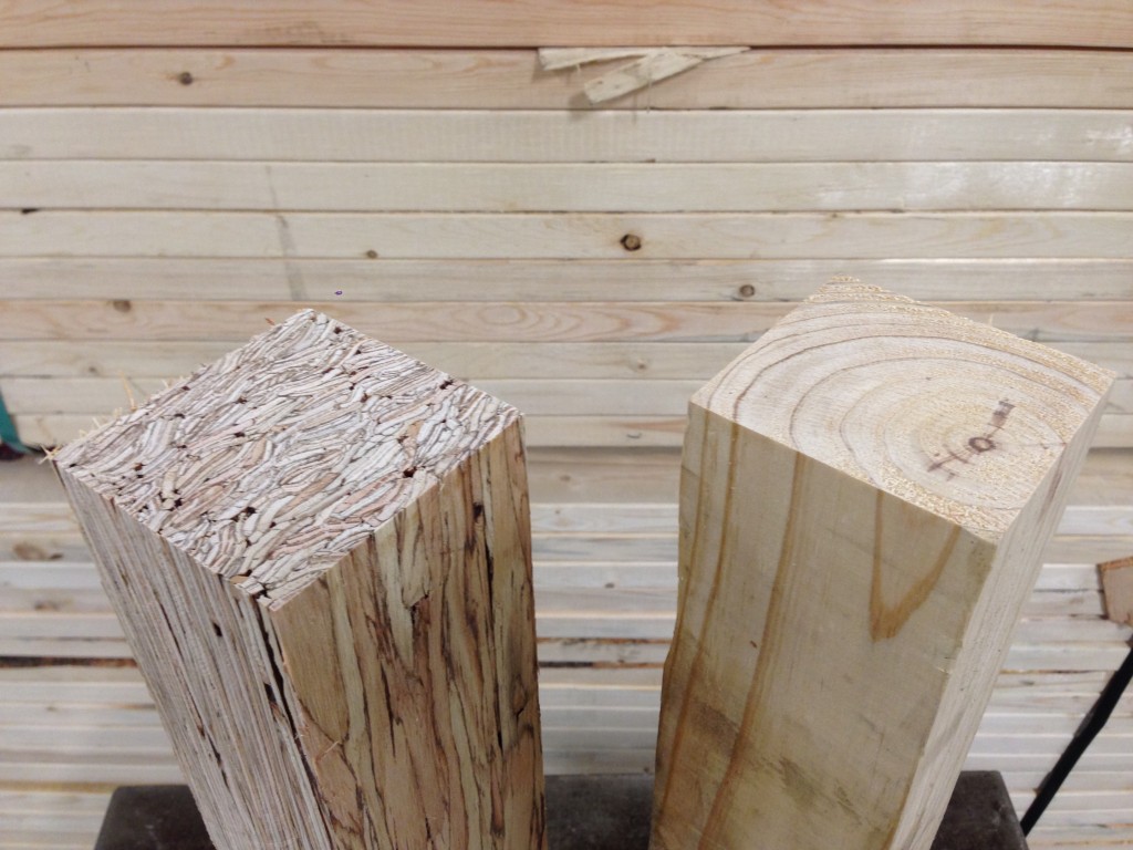
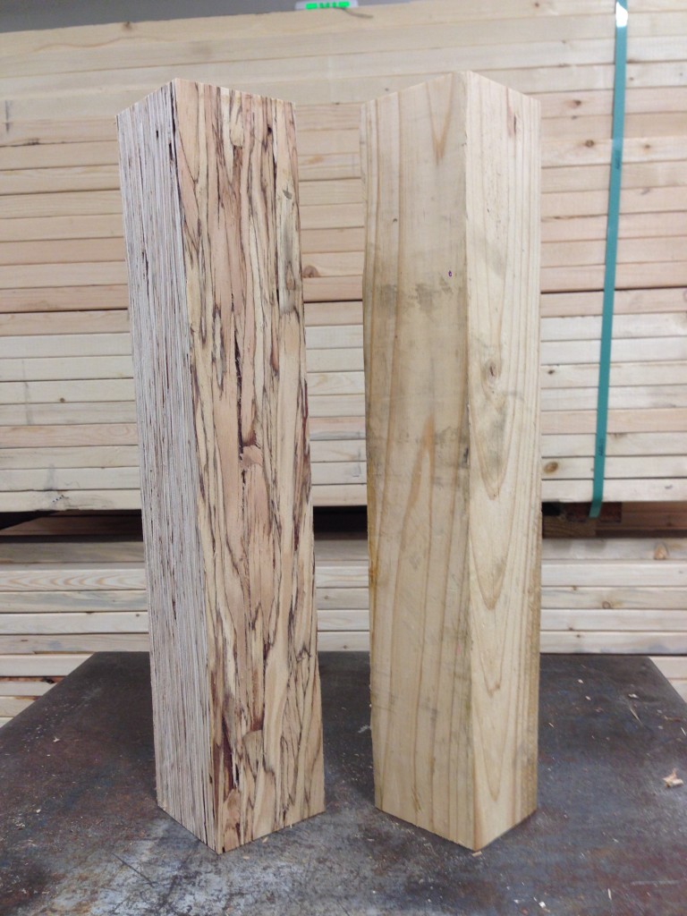
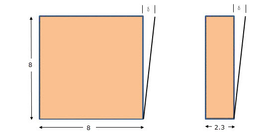
Structural composite lumber has two faces. If the cross-section is rectangular, say 3½x5¼, the narrow face will show the edges of the SCL layers. In a square section, the face that shows the SCL layers is still referred to as the narrow face. Fasteners will have lower performance when they are installed in the narrow face of SCL. While this is not an issue for beams, Simpson Strong-Tie connectors such as post bases, column caps or holdowns may have reduced allowable loads when installed on the narrow face of SCL columns.
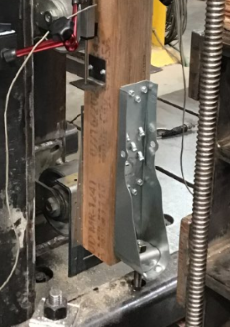
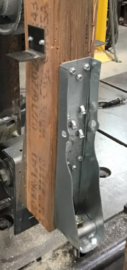

To support the use of Simpson Strong-Tie connectors installed on SCL post material, we have run many tests over the years. The reductions are published in the technical bulletins, T-C-SCLCLM25 (U.S. version) and T-C-SCLCLMCAN25. The reduction factors range from 0.45 to 1.0, and vary based on SCL material type – LSL, PSL, or LVL – and also by connector and fastener type.
It is important to understand the magnitude of the reductions. While narrow face installations may be unavoidable, engineers will need to specify the correct lumber and hardware combination to meet the design loads.
Share additional thoughts by leaving a comment.