Corrosion: The Issues, Code Requirements, Research and Solutions

When you hear $452 billion, what comes to mind? Perhaps the annual state budgets of California, Texas, Florida or New York? Maybe the combined net worth of Bill Gates, Larry Ellison, or the Walton Family? While those would be good guesses, I bet you didn’t think of corrosion! According to a May 2012 Congressional Briefing hosted by NACE International and ASM International, corrosion-related costs are a staggering 3.1% of the U.S. GDP, which is more than the individual budgets of those states above, and the combined net worth of the top 15 people listed on the Forbes 400: The Richest People in America.

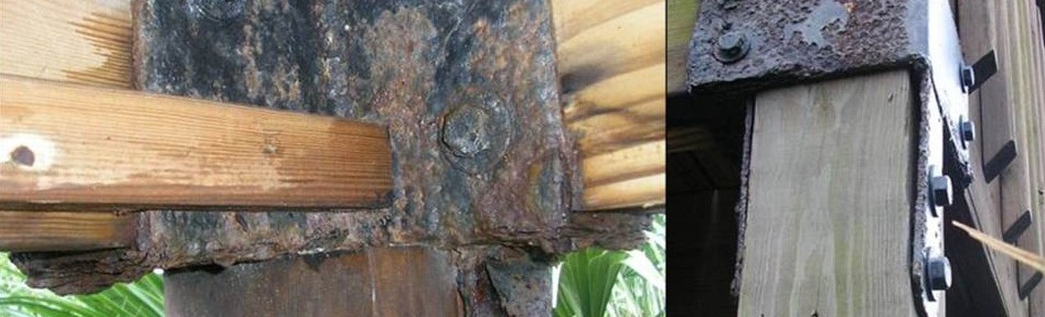
Corrosion of metallic surfaces is an electrochemical process typically involving an anode, electrolyte and a cathode. An anode is a metal zone which loses electrons when exposed to an electrolyte, an electrolyte is a non-metal electrical conductor, and a cathode is the zone where an oxidizing agent (e.g., oxygen) gains the electrons. While there are many different forms of corrosion (e.g., pitting, intergranular, wet storage stain, etc.), and various sources of causes (e.g., treated lumber, moisture level, temperature, atmosphere, air quality, etc.), other factors such as exposure related to time of wetness are equally important. In a study presented in Dr. X.G. Zhang’s book Corrosion and Electrochemistry of Zinc, time of wetness is 50% greater near the top of a structure compared to the bottom, leading to greater corrosion.

Continue Reading

Taking Wood-Framed Construction to New Heights

When I had more hair and less of it was gray, I worked on a project as an assistant engineer doing the calculations for a mixed-use building in San Jose, California. Final design consisted of four stories of wood framing over a concrete podium slab and another level of below-grade parking. At that time, my firm had designed many two- and three-story residential buildings, but common thinking was you switched to steel or concrete for taller structures because of perceived limitations in wood-framed construction.Continue Reading

Vote For Your Favorite "Creative Use of Our Product" Photo For A Chance To Win!

In my previous life as a building designer, I occasionally saw some creative installations of Simpson Strong-Tie products. These usually came in the form of an RFI where the contractor was asking for forgiveness for a misinstallation. However, this week’s post pays tribute to the creativity and ingenuity of our customers. The following photos are some of my favorite interesting applications and creative uses of our products. Some are purely utilitarian, which describes most of the aftermarket automotive uses. Others have a unique beauty while solving a problem or filling a need. Some are truly works of art and the rest are just plain silly. I hope you enjoy them as much as I do.

Tell us which picture is your favorite by posting a comment, or tell us about an interesting application or creative use for Simpson Strong-Tie products you’ve seen. We’ll be awarding five commenters with a Simpson Strong-Tie Prize Pack via random drawing (one entry per person, please). Details and rules here.

Continue Reading

Vote For Your Favorite “Creative Use of Our Product” Photo For A Chance To Win!

In my previous life as a building designer, I occasionally saw some creative installations of Simpson Strong-Tie products. These usually came in the form of an RFI where the contractor was asking for forgiveness for a misinstallation. However, this week’s post pays tribute to the creativity and ingenuity of our customers. The following photos are some of my favorite interesting applications and creative uses of our products. Some are purely utilitarian, which describes most of the aftermarket automotive uses. Others have a unique beauty while solving a problem or filling a need. Some are truly works of art and the rest are just plain silly. I hope you enjoy them as much as I do.

Tell us which picture is your favorite by posting a comment, or tell us about an interesting application or creative use for Simpson Strong-Tie products you’ve seen. We’ll be awarding five commenters with a Simpson Strong-Tie Prize Pack via random drawing (one entry per person, please). Details and rules here.

Continue Reading

Out-of-Plane Wall Anchorage Design

While the Simpson Strong-Tie Tye Gilb R&D lab in Stockton is a large testing facility, the world’s largest R&D lab is Mother Nature herself. Natural disasters such as earthquakes or storms put our engineering designs to the test. In this week’s blog post, I’ll be turning attention to wall anchorage for out-of-plane forces and the lessons we have learned from Mother Nature so far.

The 1979 building code incorporated many of the lessons learned from the 1971 San Fernando earthquake. In 1994, Mother Nature put the 1979 building code to the test with the January 17 Northridge earthquake. The Northridge earthquake showed that some of the increased design and detailing requirements in the 1979 building code worked well to improve performance over what was observed in 1971. However, it also revealed to researchers that acceleration at the roof level of single story warehouse buildings were three to four times the ground acceleration. The combination of higher than expected acceleration and excessive deformation of the wall anchorage assembly caused many wall anchorage failures.

Figure 1 Out-of-Plane Wall Anchorage Assembly

Several changes in the design forces used for wall anchorage and additional detailing requirements were incorporated in the 1997 Uniform Building Code. The requirements have been refined with each new building code, but overall the requirements and design forces have remained about the same under the current International Building Code. Wall anchorage design is governed by ASCE/SEI 7-16 Section 12.11. These provisions aim to mitigate the brittle wall anchorage failures observed in past earthquakes by increasing the design force and in Seismic Design Categories C through F, requiring:Continue Reading

Why a Structural Boundary Member Between a Truss/Rafter is Not Optional

Blocking or boundary member?

In my experience traveling across the country observing wood-framed construction, it was apparent that east of the Rocky Mountains, structural wood members in-line with supporting walls between roof framing cease to be installed. Some may call these wood members blocking and deem them as optional. And often in a humid environment, installation of these members may be ardently resisted in order to provide ample attic ventilation and prevent mold growth. It is important, however, to understand that this blocking creates the structural boundary members for the roof diaphragm and it is not optional.

Continue Reading

How Do You Use Technology To Make Your Job Easier?

I confess to being a bit of a technology junkie. I think it was around 1995 when I first overcame my fears and cracked open my computer case, installed a new hard drive and upgraded to an enormous 8 megabytes of RAM. While I still enjoy building my own home computer every now and then, it seems like keeping up with technology is a full-time job. For every new website or app, you can expect two or three more just like it to follow. Trying to filter through all of that information to find what’s useful to your specific job, process or project can be impossible.

I’ve found it’s usually best to let the need dictate the technology, versus the other way around. When I was designing buildings, contractor sketches or descriptions of field issues were often not clear (especially the ones that had been faxed 5 times!). Sometimes we could figure it out with several phone calls, but other situations would require a field visit. A photograph would work, but developing film and sending the photos would take too long. The development of inexpensive digital cameras so field questions could be e-mailed with photos really streamlined my process for responding to field issues.

Continue Reading

October 11 – Buildings At Risk: Earthquake Loss Reduction Summit

I don’t travel too much for work, so the last three weeks has been a bit different from my normal routine. On August 30, I attended an unreinforced masonry retrofit workshop in Memphis, had a sales meeting the following week in St. Louis, and the annual SEAOC convention last week in Santa Fe, New Mexico.

I have been remiss in not talking about an important summit taking place in California next month. SEAOSC is hosting the 2nd annual Buildings at Risk Earthquake Loss Reduction Summit on October 11 in downtown Los Angeles, California. The summit is a precursor to the Great California ShakeOut” event that will be held on October 18.The summit will serve as a forum to not only increase awareness of seismic risk, but spur action. This will be an important conference not only for structural engineers working in seismic areas, but for building officials, architects, building owners, insurance companies, and first responders. The sessions will stress the benefits of mitigation and encourage the different stakeholders to work together on solutions.

Early registration for a discounted rate and a chance to win an iPad ends today, but there is still time to register.

– Paul

“Sunny With A Chance Of Earthquake”

With scientists predicting a 99% chance of a 6.7 magnitude earthquake striking Southern California within the next 30 years, California weather forecasters may want to remind residents that the location which gives lots of golden sunshine year round is also one of high seismic risk.

Recent earthquakes in cities similar to Los Angeles, San Francisco and Memphis have served as a reminder of the damage and disruption a major earthquake can have on a community. Through lessons learned from past earthquakes and research performed by the construction industry, there are many tools available geared toward residential buildings to reduce damage and resist collapse.

Continue Reading

Cantilever Floor Induced Load Path Concerns

IBC Section 1604.9 requires structural members, systems, components and cladding be designed to resist forces due to earthquakes and wind, with consideration of overturning, sliding and uplift. It also states that a continuous load path be provided for transmitting these forces to the foundation. Seems obvious to engineers that a continuous load path is needed, but it’s still nice to have the code say so.

But what happens if your structure’s upper and lower story walls do not stack? How do you create the required continuous load path? As engineers, we try to steer the architect towards eliminating the offset, making things line up, and keeping construction simple. But architectural requirements cannot always accommodate simple, and non-stacking walls occur all the time.

Continue Reading