Bob Leichti, Senior Technical Manager, Research and Development. Prior to joining Simpson Strong-Tie in 2012, Bob was an Engineering Manager covering structural fasteners, hand tools, regulatory compliance and code reports for a major manufacturer of power tools and equipment. Prior to that, Bob was a Professor in the Department of Wood Science and Engineering at Oregon State University. He received his B.S. and M.S. from the University of Illinois, and his M.S. and Ph.D. from Auburn University.
He huffed, and he puffed, and he blew the roof sheathing off! That’s not the way kids’ tale goes, but the dangers high winds pose to roof sheathing are very real. Once the roof sheathing is gone, the structure is open and its contents are exposed to the elements and much more vulnerable to wind or water damage. It is a storyline that we meet all too often in the news.
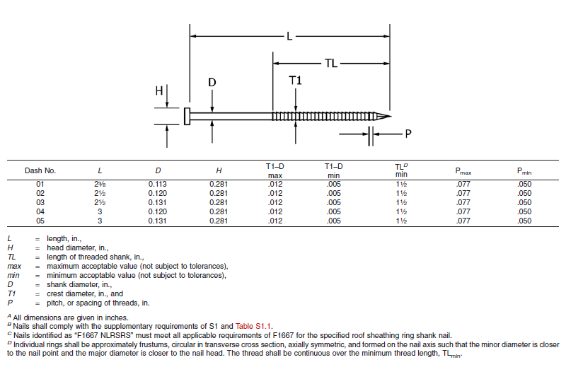
About two years ago, the ASTM subcommittee on Driven and Other Fasteners (F16.05), addressed fastening for roof sheathing in high-wind areas by adding a special nail to ASTM F1667-17 – Standard Specification for Driven Fasteners: Nails, Spikes and Staples. The Roof Sheathing Ring-Shank Nail was added to the standard as Table 46. Figure 1 illustrates the nail and lists its geometrical specifications. This is a family of five ring-shank nails that can be made from carbon steel or stainless steel (300 series). Specific features of these nails are the ring pitch (number of rings per inch), the ring diameter over the shank, the length of deformed shank and the head diameter. Also, note B specifies that the nails shall comply with the supplementary requirement of Table S1.1, which tabulates bending yield strength. In this diameter class, the minimum bending yield strength allowed is 100 ksi.
Figure 1. Roof Sheathing Ring-Shank Nails (ASTM. 2017. Standard Specification for Driven Fasteners: Nails, Spikes and Staples, F1667-17. ASTM International, West Conshohocken, PA.)
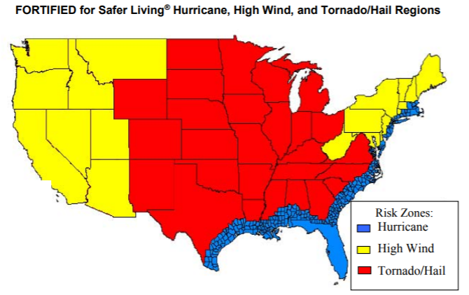
The IBHS (Insurance Institute for Business and Home Safety) discusses roof deck fastening in its Builders Guide that describes the “FORTIFIED for Safer Living” structures. The IBHS FORTIFIED program offers solutions that reduce building vulnerability to severe thunderstorms, hurricanes and tornadoes. Keeping the roof sheathing on the structure is critical to maintaining a safe enclosure and minimizing damage, and roof sheathing ring-shank nails can be part of the solution. As Figure 2 from IBHS (2008) shows, every wood-frame structure has wind vulnerability.
Figure 2. Hurricane, high wind and tornado regions of the US (IBHS. 2008. Builders Guide, Fortified for Safer Living. Tampa, FL. 81 pp.)
More importantly for the wood-frame engineering community, the Roof Sheathing Ring-Shank Nails are being included in the next revision of the AWC National Design Specification for Wood Construction (NDS-2018), which is a reference document to both the International Building Code and the International Residential Code. You will be able to use the same NDS-2018, chapter 12 withdrawal equation to calculate the withdrawal resistance for Roof Sheathing Ring-Shank Nails and Post Frame Ring-Shank nails. The calculated withdrawal will be based on the length of deformed shank embedded in the framing member. Also, Designers need to consider the risk of nail head pull-through when fastening roof sheathing with ring-shank nails. If the pull-through for roof sheathing ring-shank nails is not published, you will be able to use the new pull-through equation in the NDS-2018 to estimate that resistance.
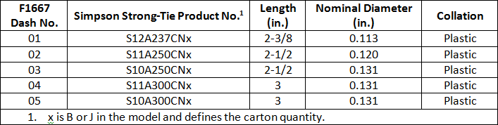
Simpson Strong-Tie has some stainless-steel products that meet the requirements for Roof Sheathing Ring-Shank Nails. These will be especially important to those in coastal high-wind areas. Table 1 shows some of the Simpson Strong-Tie nails that can be used as roof sheathing ring-shank nails. These nails meet the geometry and bending yield strength requirements given in ASTM F1667. See the Fastening Systems catalog C-F-2017 for nails in Type 316 stainless steel that also comply with the standard.
Table 1. Simpson Strong-Tie collated nails made from Type 304 stainless steel that comply with F1667-17 specifications for Roof Sheathing Ring-Shank Nails.
Improve your disaster resilience and withstand extreme winds by fastening the sheathing with roof sheathing ring-shank nails. You can find Roof Sheathing Ring-Shank nails in ASTM F1667, Table 46, and you will see them in the AWC NDS-2018, which will be available at the end of the year. Let us know your preferred fastening practices for roof sheathing.
Experiential learning — has it happened to you? Certainly it has, because experiential learning is learning derived from experience. It happens in everyday life, in engineering and in product development, too. For example, experience has taught us that after a product is launched, our customers will find applications for the product that were never expected or listed in the product brief. Also, experience has shown us that larger fasteners tend to be placed in applications that have greater structural and safety demands.
When the larger Deck-Drive™ DWP screws were manufactured, we decided that they should be marketed as “load-rated” screws because they were big enough to support physically large parts and would be expected to provide structural load resistance.
So what is a “load-rated” screw? To Simpson Strong-Tie, a load-rated screw is a threaded fastener that has controlled dimensions and physical properties, as well as validated connection properties. Load-rated fasteners are also subject to the same quality inspection that would occur if they were undergoing an evaluation report.
This week we are blogging about being “galvanic,” and we don’t mean with respect to people, but with respect to the corrosion that occurs between dissimilar metals.
Here is a question, and it is not a joke: What is one significant result that can occur when you have both electrochemical activity and intimate contact? The answer is galvanic corrosion.
Galvanic corrosion can take place when two or more metals of different electrochemical activity are in intimate contact in the presence of an electrolyte. The dissimilar metals form a galvanic couple, and with the aid of the electrolyte, a galvanic current flows between the metals of the galvanic couple. The more anodic metal corrodes in the presence of the more cathodic metal. In fastening systems, this can be a significant issue because the metal of the fastener often does not match that of the connection materials, making their electrochemical activity dissimilar.
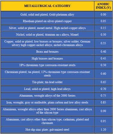
Let’s examine the requirements for galvanic corrosion to occur.
First – In the most common instance, the metals are dissimilar, which means that the metals have different chemical potentials. You may be familiar with the galvanic series where metals are rated by their tendency to give up electrons in a salt-water solution. See Figure 1 for a chart of the galvanic series. The chart is structured with the most cathodic metals at the top and progresses to the most anodic at the bottom. The anodic index shown in the chart is normalized so that gold is the minimum numerical value, while zinc has the greatest numerical value. Stainless steel (300 series) is hidden in the terminology of “18% Chromium type corrosion-resistant steels.” In this chart, the stainless steel is assumed to be passivated.
Second – The metals must be in direct contact.
Third – An electrolyte must be present to facilitate the movement of electrons. The electrolyte in construction environments is usually plain water that occurs in the form of precipitation, condensation or water splash. Electrolytes that are solutions of chlorides (for example, salt water) are particularly effective electrolytes because they are more conductive.
The size of the anodic and cathodic parts can also be important in galvanic corrosion. If the anodic area is small relative to the cathodic exposed area, then the severity of the anodic corrosion is amplified. We can write an equation to explain the role of area in the galvanic process. We know that no corrosion will occur if the corrosion current density (icor) in μA/cm2 is the same for the anode (icor-a) and the cathode (icor-c). Here we are using a and c as subscripts to identify the anode and the cathode in the galvanic system. We know that current density is a function of total anodic current (I) in μA (where italicized A is amps), and the exposed area (A) is in cm2, which (according to ASTM G102-89) can be written as
icor = Icor/A
No galvanic corrosion transpires if icor-a for the anodic material is equivalent to icor-c of the cathodic material, which is to say Icor/Aa = Icor/Ac. However, when Ac ≠ Aa, then the corrosion function is not balanced, and relative areas can drive the severity of the galvanic reaction. Inasmuch as area can affect the galvanic process, it will help connection performance if the more anodic material is larger than the more cathodic material. And, by making the Aa>>Ac, we can arrest or minimize the galvanic process. Generally, this means it is best to have a fastener that is more cathodic than the materials being fastened.
We also know that the environment can affect galvanic activity. The differential in the anodic index of dissimilar metals is amplified in harsh environments, but in controlled environments, a greater differential in anodic index can be tolerated.
Let’s summarize some best fastening practices for preventing galvanic conditions that could undermine an otherwise good connection design (Claus, L. 2014. “Galvanic Corrosion.” Fastener Technology, April, pp. 64–66.):
Use fasteners that are galvanically similar to the connection materials.
Isolate the dissimilar materials by using a plastic washer or durable coating.
Prevent entrapment of water or shield the connection from direct weather exposure.
If the fasteners are dissimilar from the connection materials, choose a fastener that is cathodic relative to the connection materials.
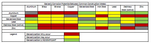
Some good information is available that can help to avoid a galvanic design challenge. First, see Figure 2. This chart provides color-coded galvanic compatibility that is fast and easy to use. The chart suggests material combinations where there will be galvanic action (red), material combination that might demonstrate galvanic activity (yellow), and material combinations that will have insignificant galvanic activity (green).
Figure 2. Galvanic compatibility between common construction materials (Stuart, D.M. 2013. Dissimilar Materials. PDHonline course S118. Fairfax, VA)
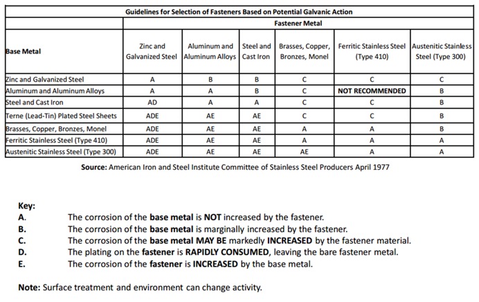
Then see Figure 3 because it gives more information about choices of materials for the fastener and connection materials. Here the probable results of galvanic corrosion to the fastener and base metals are described for various common combinations of common construction materials. It will help to explain which parts of the connection will be affected by galvanic corrosion and how severe the corrosion is likely to be.
Figure 3. Guidelines for selecting fasteners based on potential galvanic action (Stuart, D.M. 2013. Dissimilar Materials. PDHonline course S118. Fairfax, VA)
We know that you have many challenges when designing fastener connections, and it is our hope that this discussion helps you make informed choices when fastening dissimilar materials. Remember: Galvanic corrosion happens! Let us know if you have any comments.
This week we’re blogging about corrosion, and we’re not talking about rusting of the soul — we’re talking about oxidation of steel.
In 2014, we reviewed our corrosion protection recommendations for new catalog publications. In doing so, we realized that we could facilitate selection of hardware and fasteners if our Corrosion Resistance Classifications for treated wood were linked to common design conditions described in the codes. We made some revisions to our Corrosion Resistance Classifications during that exercise. This blog post talks about those changes and some current related activity in the wood treatment industry.
The common design conditions for corrosion-resistant wood construction include the wood materials with associated treatments and the environmental corrosion agents. The American Wood Protection Association (AWPA), which is an ANSI-accredited consensus standards organization, publishes the code-referenced standard, AWPA U1-15 Use Category System: User Specifications for Treated Wood.
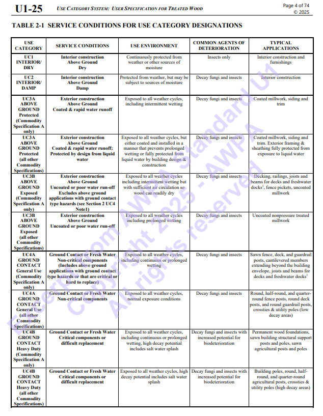
When you specify treated wood, this is the standard that defines the appropriate treatment chemicals and chemical retentions depending on the exposure condition and bio-hazard, which the AWPA has summarized into a Use Category (UC) system. Figure 1 is a clip from the AWPA web site that gives a glimpse at the UC system. As the UC rating increases from UC1 to UC5, the chemical retention increases because the bio-hazard is increasing. Corrosion hazards are directly related to the combination of treatment chemical, treatment chemical retention and use environment.
Figure 1. Summary of AWPA Use Category System https://awpa.com/images/2025/U1-25_excerpt.pdf
The AWPA UC system does not include environmental corrosion agents. As a result, we had to separately integrate those with treatment chemical effects as we developed the corrosion resistance classifications.
Finally, one more evaluation system had to be addressed: the exposure conditions of ICC-ES AC257 — Corrosion Resistant Fasteners and Evaluation of Corrosion Effects of Wood Treatment Chemicals. In the end, we developed Corrosion Resistance Classifications that considered the AWPA Use Categories, environmental corrosion agents and the ICC-ES AC257 exposure conditions.
Some of you may be thinking that we have not mentioned another aspect of corrosion — galvanic corrosion. Galvanic corrosion results when metals with dissimilar electrical potentials are placed in contact in the presence of an electrolyte (water). We’ll take up galvanic corrosion in a subsequent blog post.
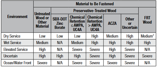
Our basic Corrosion Resistance Classification table is shown in Figure 2.
Figure 2. Corrosion Resistance Classifications (from C-F-2025, p. 18, or strongtie.com)
The ratings shown in the table — Low, Medium, High and Severe — refer to the corrosion resistance of Simpson Strong-Tie coating systems and base metals. An example of a coating system that is rated “Low” is paint or electro-galvanized zinc. An example of a material rated for “Severe” corrosion conditions is Type 316 stainless steel.
To use the Corrosion Resistance Classifications table, find the Environment, then move to the correct column in the Material to Be Fastened section; identify a rating. Then look in the companion table labeled “Corrosion Resistance Recommendations” to identify a coating or base metal that is appropriate for your project. Be sure to read the table notes to the Corrosion Resistance Classifications for exceptions and limitations. We implemented this system to simplify product selection. Let’s take a look at each aspect that contributes to the Corrosion Resistance Classifications table.
Environment
The environment captures the moisture, atmospheric conditions and other elements that affect corrosion rate. “Dry Service” usually means an interior space with low moisture content or dampness. No liquid water is present in this sort of environment. The absence of moisture limits the electrochemical reaction needed to produce what we see as corrosion. “Wet Service” usually means exterior exposure and involves liquid water as direct exposure or condensation and wood moisture contents that can exceed air-dry conditions and may be temporary or persist for prolonged periods. We incorporated environmental agents with the “Elevated Service and Ocean/Waterfront” conditions. These environmental agents include fumes, acid rain, airborne salinity, etc. The “Uncertain Environment” was included for the Designer who does not know the corrosive conditions in service.
Material Being Fastened
Here we distinguish between clean materials and wood treated with chemicals — wood preservatives or fire-retardant chemicals (FRT). Untreated softwoods used for framing are generally not significantly corrosive. This does not include cedars and redwood, which are a special case. Cedars tend to be corrosive and particularly prone to staining when fastened with carbon steel hardware and fasteners. As a result, our recommendations for untreated softwoods are generally a function of the environment — moisture, weather exposure and corrosion agents such as salt spray, sulfur or fertilizer fumes and acid rain are all examples.
Some treatment chemicals do not significantly increase the corrosion hazard. These are the SBX-DOT treatment chemicals (inorganic boron and borate treatments). These are not typically used in exterior environments or for high-moisture conditions. The preservatives are not chemically bound to the wood and they can leach out under exposure to liquid moisture, which would leave the wood unprotected. The corrosion hazard attendant to these chemicals is similar to that of untreated wood and the codes permit the use of bare carbon steel in contact with wood treated with these chemicals (IBC2024, Section 2304.10.6.1 and IRC2025, Section R304.3.1 (exception 3)).
Most of the waterborne chemicals in common use contribute to an elevated corrosion hazard. Some of the common wood treatment chemicals include formulations of alkaline copper quaternary (ACQ), copper azole (CA), ammoniacal copper zinc arsenate (ACZA) and micronized copper azole (MCA). The AWPA UC system defines the exposure conditions for each Use Category as well as the chemical retention required to prevent a decay failure. The MCA formulations are alternatives to those specified in the code-referenced standard through the evaluation report process and are not standardized by the AWPA. The evaluation report process for wood preservatives requires the submission of evidence in compliance with ICC-ES AC326 — Proprietary Wood Preservative Systems — Common Requirements for Treatment Process, Test Methods and Performance.
We realize that UC4A is a general-use ground-contact condition, and further, it is the maximum necessary specification for treated wood in many building applications. The Simpson Strong-Tie Corrosion Resistance Classifications recognize that the corrosion hazard of treatment chemical retentions for UC4A in Wet Service is a “Medium” corrosion condition (with the exception of ACZA, which is rated “High” in Wet Service). This means that carbon steel products with sufficient corrosion resistance (e.g., ZMAX, double barrier coating, etc.) can be used in these conditions assuming no other corrosion-causing agents are present.
On the other hand, the moisture conditions and treatment chemical retentions are elevated in UC4B and UC4C, and there is also a potential for salt exposure, which further escalates the corrosion hazard. In these conditions, stainless steel is generally recommended for connectors and fasteners as the best material for mitigating the corrosion risk.
The last column in the Corrosion Resistance Classifications table is devoted to FRT wood. Fire-retardant treatment chemicals are proprietary and are deemed to meet the requirements of the codes through the evaluation report process (ICC-ES AC66 — Acceptance Criteria for Fire-Retardant-Treated Wood). We cannot evaluate the corrosion resistance of hardware to all of the FRT formulations. However, we have reviewed most of the FRT evaluation reports for corrosion information. The corrosion effects of FRT chemicals, like preservative treatment chemicals, are minimized in dry-service conditions because the electrochemical reaction cannot progress or is slowed without an electrolyte. The Corrosion Resistance Classifications reflect that information. The Designer should always follow the FRT evaluation reports in addition to considering our recommendations.
It is important to note that the Corrosion Resistance Classifications are not associated with specific applications. Rather, the ratings are based on the integrated effects of the environment and the wood treatment where the chemical retentions given in the AWPA Use Category system play an important role in the ratings. This makes it relatively straightforward to select hardware that is adequate for a design environment.
Changes to the AWPA U1 Standard and Effects on Corrosion Resistance Classifications
As noted here and in the online JLC article, wood preservative chemicals can achieve compliance with the codes by either of two methods:
The product is a generic product (e.g., ACQ-D or CA-B) and is listed in the AWPA U1 standard; or
The product has an evaluation report obtained by submitting evidence in accordance with ICC-ES AC326 — Proprietary Wood Preservative Systems — Common Requirements for Treatment Process, Test Methods and Performance.
You may be aware that the AWPA is revising its code-referenced standard, AWPA U1-15, Use Category System: User Specification for Treated Wood. The consensus process is ongoing and is not complete. However, AWPA member chemical companies (Viance, Koppers, and Arch) have placed information in the market. In parallel with the AWPA, ICC-ES has modified AC326 to reflect the changes ongoing in the AWPA U1 standard. Simpson Strong-Tie has been in contact with the AWPA, other industry associations and industry professionals to understand the potential effects on metal hardware of the AWPA U1 and ICC-ES AC326 revisions.
The proposed revisions to the AWPA U1 standard modify the definitions for UC3A, UC3B, UC4A, UC4B and UC4C. The most important revisions are to UC3B and UC4A. The new definition for applications in UC3B suggests that beams and joists in decks and docks may have bio-hazards that exceed the UC3B assumptions, while the new UC4A definition will include above-ground applications with ground- contact hazards. The revised AWPA U1 standard will be published in the May–June 2016 time frame; AWPA U1-16 will be included in the 2018 codes.
The revision to ICC-ES AC326 also modifies the definitions for UC3B, UC4A and UC4B. ICC-ES AC326 has an implementation date of July 2016, which will cause some changes to specifications this summer. Micronized copper azole (MCA) formulations are the most common treatment chemicals that will be affected by this action.
Revisions to the Use Category definitions are being driven by two issues:
Wood treated for UC3 is sometimes used in near-ground applications where the bio-hazard is more like UC4.
Under-treatment compromises the margin of safety to bio-hazards, which can lead to decay failures.
Rather than revisit the retention specifications in AWPA U1 standard, the AWPA is modifying the definitions for the Use Categories that are involved, and that language has been carried into ICC-ES AC326 to ensure that the two systems are consistent with each other. The result of changes to the Use Category definitions will likely cause some specifications to change from UC3B to UC4A or from UC4A to UC4B. The main effects will likely be to specifications in eastern and southern states, where there may be more chemical in the wood to meet retention specifications.
The Simpson Strong-Tie Corrosion Resistance Classifications make specific reference to the corrosive levels of environmental conditions and the chemical treatment and retentions of the AWPA Use Categories, not to applications. As a result, the AWPA U1 revisions and the parallel changes to ICC-ES AC326 will not necessitate a change in our corrosion recommendations, because the chemical retentions for each Use Category have not changed. However, your hardware specifications could change for typical applications depending on the Use Category of the treated wood in your project. Our information suggests that this issue is still not settled within the industry, and we will pass along information as we learn it.
Simpson Strong-Tie is currently preparing new catalogs for the coming year and will be updating the corrosion information in those publications and our website. We’re interested in your experience with our Corrosion Resistance Classifications and whether you have suggestions for how we might make the content more useful to you.
Structures and connections can be designed either using Allowable Strength Design (ASD) method or Load and Resistance Factor Design (LRFD) method. In the ASD method, the allowable strength is calculated by dividing the nominal strength by a safety factor. In the LRFD method, the design strength is calculated by multiplying the nominal strength by the resistance factor. In design, the adjusted ASD design value is compared to a calculated load or stress. As long as the adjusted ASD design value exceeds the calculated load of stress, then the ASD design value is judged safe. In LRFD design, the nominal strength is equated to factored loads. If the factored strength is greater than the factored loads, then the design can be accepted. ASD is the more common method adopted in the professional world.Continue Reading
This week’s post was written by Bob Leichti, Manager of Engineering for Fastening Systems. Prior to joining Simpson Strong-Tie in 2012, Bob was an Engineering Manager covering structural fasteners, hand tools, regulatory compliance and code reports for a major manufacturer of power tools and equipment. Prior to that, Bob was a Professor in the Department of Wood Science and Engineering at Oregon State University. He received his B.S. and M.S. from the University of Illinois, and his M.S. and Ph.D. from Auburn University.
When test results don’t make sense, we start by eliminating causes of the problem. When our withdrawal test values came up low, we checked the load cell calibration, the specific gravity of the wood, the nail dimensions, even the units – everything was correct. So why were the nail withdrawal values so low? More wood, more nails, more tests – same results. Ultimately, we concluded that the withdrawal resistance of stainless-steel, smooth-shank nails is not well described by the withdrawal function in the 2012 NDS, section 11.2.3, equation 11.2-3.Continue Reading
We use cookies on this site to enhance your user experience. By clicking "I AGREE" below, you are giving your consent for us to set cookies. Privacy PolicyI AGREE
Privacy & Cookies Policy
Privacy Overview
This website uses cookies to improve your experience while you navigate through the website. Out of these cookies, the cookies that are categorized as necessary are stored on your browser as they are essential for the working of basic functionalities of the website. We also use third-party cookies that help us analyze and understand how you use this website. These cookies will be stored in your browser only with your consent. You also have the option to opt-out of these cookies. But opting out of some of these cookies may have an effect on your browsing experience.
Necessary cookies are absolutely essential for the website to function properly. This category only includes cookies that ensures basic functionalities and security features of the website. These cookies do not store any personal information.
Any cookies that may not be particularly necessary for the website to function and is used specifically to collect user personal data via analytics, ads, other embedded contents are termed as non-necessary cookies. It is mandatory to procure user consent prior to running these cookies on your website.