Cold-Formed Steel Curtain-Wall Systems

In August 2012, Simpson Strong-Tie launched a comprehensive, innovative solution for curtain-wall framing. Our lead engineer for developing our line of connectors for curtain-wall construction explains the purpose of the curtain wall with the illustrations below.

steel-stud-framing
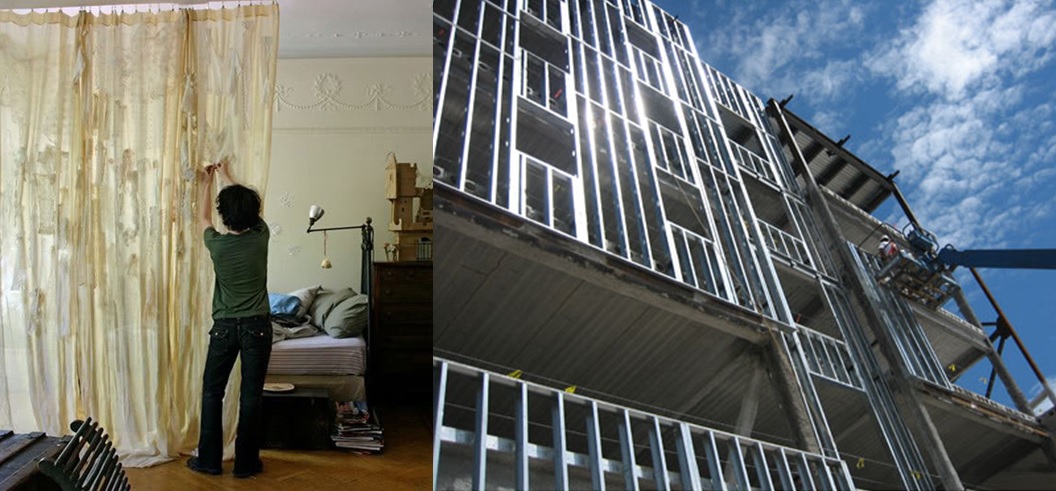
First, curtain walls are not what you put up if you shared a room with your brother and sister when you were growing up. When I first learned about the use of cold-formed steel curtain walls, I laughed and thought: “Gosh, how useful this would be for someone growing up with 5 siblings in one bedroom!” I have always enjoyed the sense of humor that our engineers use to help explain technical topics.

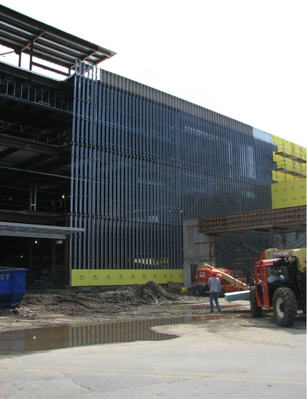
Curtain walls can be described as exterior building walls with the primary purpose of protecting the interior building against the exterior weather and natural phenomena such as sun exposure, temperature changes, earthquakes, rain and wind.

To put it in structural terms, a curtain-wall system consists of non-load-bearing exterior walls that must still carry their own weight. Curtain walls are not part of the primary structural framing for the building, but they typically rely on the primary structural framing for support. Additionally, curtain walls receive wind and seismic loads and transfer these forces to the primary building structure.

Types of Curtain Walls

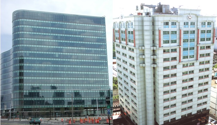
Glass and cladding curtain walls make up two basic types of curtain-wall systems. Glass curtain-wall systems are usually designed using aluminum-framed walls with in-fills of glass. The cladding curtain wall is a system with back-up framing that is covered in some type of cladding material. The cladding curtain-wall system is the type in which Simpson Strong-Tie products can be used.

mid-rise-buildings-1
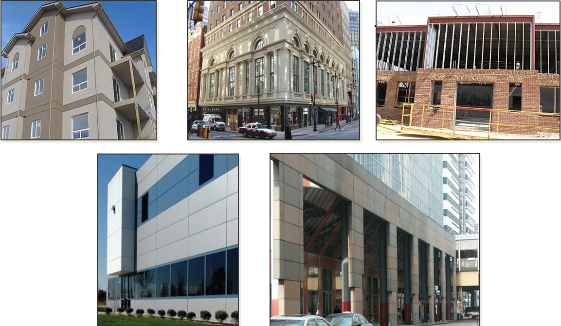
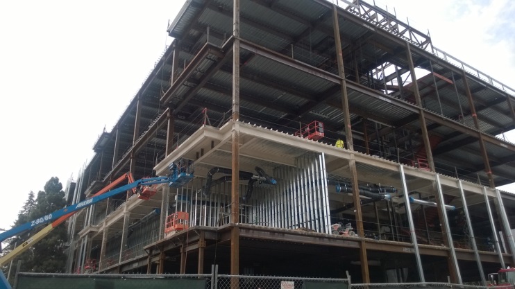
The back-up framing is the structural element of the curtain-wall system. It is typically constructed with cold-formed steel studs ranging from 31/2″ to 8″ deep, in 33 mil (20 ga.) to 97 mil (12 ga.) steel thicknesses. The framing studs are typically spaced at 16″or 24″ on center. There are many different types of cladding materials. They include, but are not limited to, exterior insulation finish systems (EIFS), glass-fiber-reinforced concrete (GFRC), bricks, metal panels and stone panels.

building-material-examplesDeflection

One essential function of the curtain wall is to allow for relative movement between the curtain-wall system and the main building structure. At first, it was not obvious to me why making this allowance was necessary, but our product development team creatively explained some of the reasons why this is an important must-have feature for curtain walls.

deflection-examples
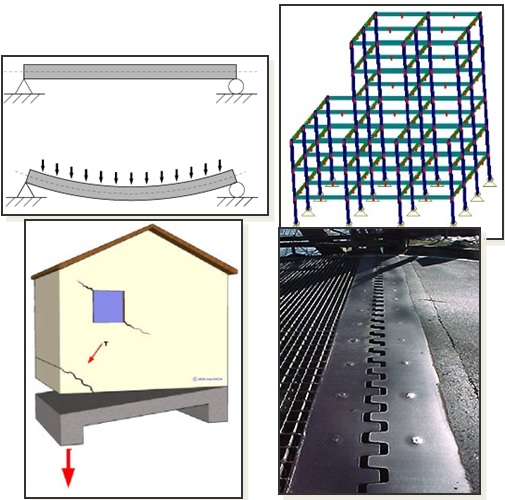
First, the primary building will move up and down as it is loaded and unloaded by the live-load occupancy, similar to beam live-load deflections.

Second, the structure sways and has torsional displacement due to movement from lateral wind or seismic loads.

Third, concrete structures typically encounter creep and shrinkage, and there may be foundation differential settlement or soil compression from high-gravity loads.

Lastly, the temperature differential may cause the building elements to expand and contract, which, again, can result in relative movement between structural elements. This is similar to a bridge’s steel plate expansion joint system.

And if you are a curious designer like me, you probably wonder why the relative vertical moment is so significant in engineering design.

One key reason is to ensure that the curtain walls do not collect gravity loads from the building, so as to prevent overloading and possible failure of the stud framing. In addition, a well-designed curtain-wall system needs to retain the primary structural load path as intended by the building designer.

The other reason is to protect the cladding of the building. If you remember earlier, the cladding material may be marble, granite or natural stones that are often very expensive and heavy. In some cases, the cladding can be one of the most expensive systems in a building. And there are times when it’s much more cost-effective to design for relative movement than it is to over-design structural framing to address the stringent deflection requirements.

Construction Type

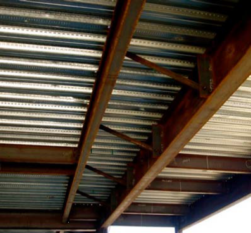
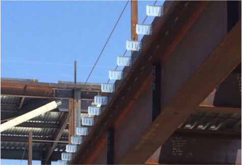
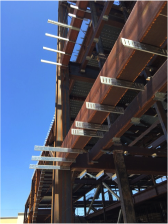
Bypass framing is a term that is often used in curtain-wall construction. In this system, the metal studs bypass the floor and hang off the outside edges of the building. You can see from the illustration how the studs run past, or bypass, the edge of the slab. In this case, the studs are supported vertically on the foundation at the bottom, and then run continuously past multiple floor levels.

Picture by Don Allen of Super Stud Building Products.

In steel construction, concrete fill over metal deck is typically constructed with a heavy-gauge bent plate or structural angle. Connectors can attach directly to the steel angle or the web of an edge beam.

Simpson Strong-Tie SCB Bypass slide clip connections.
SSB Bypass Framing Slide-Clip Strut connections.


It may seem that this type of construction is too complex and requires great efforts to detail the many connections needed to hang the curtain wall off the outside of the building. So what are the compelling reasons to choose bypass framing construction?

Bypass framing can accommodate flexibility for the architect. In another words, the bypass configuration easily allows architects to create reveals, set-backs and other architectural features.  Plus, there are fewer joints to detail for movement when stud length can run continuously for several floors.  Another benefit is that the exterior finish can also be installed on a curtain-wall system with a tighter tolerance than the edge of the structure.

One other special bypass framing type is known as ribbon window or spandrel framing. Ribbon windows are a series of windows set side by side to form a continuous band horizontally across a façade. The vertical deflection for this type of bypass framing is typically accommodated at the window head. This type of bypass usually works well for panelized construction.

www.glassmagazine.com

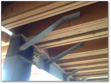
Another common curtain-wall system is infill framing, where the studs run from the top of one floor to the underside of the floor above. Sometimes it’s a challenge to attach bypass framing to the edge of thin concrete slabs. In the following illustration, deflection is designed at the top track of wall panels.

bypass-framing-in-actionIn Part 2 of this blog post series, I will provide more details about how we have innovated products to be used for this application, plus a more comprehensive post about the products we offer and how they are typically used.

In the meantime, you can check out our product offering. Our recent SC slide-clip and FC fixed-clip connectors are designed for high-seismic areas.

I would like to invite you to comment and provide feedback on this topic and tell us whether you’ve had any experience working with a Designer on a CFS curtain-wall project. If you are a Designer who specializes in this discipline, how are you designing curtain-wall systems for seismic forces?


The New Truss Design Standard: Enter to Win A Copy of ANSI/TPI 1-2014 National Design Standard for Metal Plate Connected Wood Truss Construction

If you are like me, then you enjoy this time of the year. Instead of looking back and reviewing the events of the past year, this is the month for looking ahead at the year to come and what’s in store. So what is in store for 2015?

For the truss industry, there is a new truss design standard that was just released the last week of December. Still hot off the press, the ANSI/TPI 1-2014 standard is a revision to the 2007 edition and is referenced in the 2015 International Building Codes.

While the 2015 I-Codes might take some time for some municipalities to adopt, others are gearing up for adoption of the 2015 I-Codes as early as mid-2015. Either way, it is always good to know what is in the latest and greatest code-referenced design standards. So here’s a look at the new ANSI/TPI 1-2014 truss design standard:

The New ANSI/TPI 1-2014 Standard

First, here is a brief primer on the TPI 1 standard. The Truss Plate Institute (TPI) published the first truss design criteria in 1960. Many updates to these design criteria followed after that, and in 1995, TPI published its first ANSI-accredited truss design standard, ANSI/TPI 1-1995. Subsequent editions of this American National Standard have included ANSI/TPI 1-2002, ANSI/TPI 1-2007, and now ANSI/TPI 1-2014. All of the TPI standards, including archived copies going all the way back to TPI-60, are available from TPI (www.tpinst.org). Here is a link to the overview of non-editorial changes from ANSI/TPI 1-2007 to ANSI-TPI 1-2014.

While the 2007 edition included many significant revisions to the previous edition, the 2014 standard has relatively few substantive changes to the 2007 edition, which is good news for those who are still trying to catch up. Chapter 2 covers the design responsibilities involved in metal plate connected wood truss construction and looks different at first glance because it has been reorganized. However, the actual “Design Responsibilities” as they were defined in TPI 1-2007 have not changed.

In short, two separate sections in TPI 1-2007, which address design responsibilities in projects that require registered design professionals and projects that do not, have now been combined into one section. The “Truss Design Engineer” is simply referred to as the “Truss Designer” and the “Registered Design Professional for the Building” is simply the “Building Designer.” If the project requires registered design professionals, then the Truss Designer and Building Designer will be registered design professionals. Regardless of whether or not those two parties are registered design professionals, their responsibilities relating to the design and application of metal plate connected wood trusses are the same, so defining those responsibilities once within the TPI standard simplifies things and makes more sense.

Not new to the wood industry, but new to TPI 1-2014, are provisions for Load and Resistance Factor Design (LRFD). AF&PA incorporated LRFD provisions into the 2005 National Design Specification (NDS) for Wood Construction, and the TPI standard has followed suit, using the same basic approach as the NDS.

The section in TPI 1-2014 with the most changes is the section on deflection criteria. The deflection criteria have been revised in the last three editions of the TPI standard. Starting in TPI 1-2002, a requirement was added to consider creep in total deflection calculations. However, specific creep factors were not specified in the standard and were only presented in the Commentary. In the 2007 edition, creep factors were moved into the standard, and the total deflection calculation explicitly specified a component due to creep of no less than 50 or 100 percent of the initial deflection for long-term loads for dry and green (wet service) use, respectively. This was consistent with the 1.5 and 2.0 creep factors specified in the NDS for total deflection calculations for seasoned and unseasoned conditions.

Between the 2007 and 2014 editions, an inconsistency was discovered between the TPI 1 deflection criteria and the deflection limits in the U.S. model building codes. While the intent of the TPI standard was to present the same basic L/xxx deflection limits for Live Load and Total Load as the model building codes, it was discovered that the IBC deflection limits for “DL + LL” were actually intended to address only the creep portion of the dead load deflection plus the immediate live load deflection. So although long-term deflection including proper creep considerations can be an important consideration in the overall design of the building, it is not intended to be used to limit the design of a truss with respect to building-code established limits on vertical deflection.

Excerpt from the ANSI/TPI 1-2014 Commentary

To resolve the issue of inconsistent methods used in the building industry to specify deflection limits, the 2014 edition now distinguishes between the following:

• “Deflection due to Live Load Plus Creep Component of Deflection due to Dead Load” for purposes of meeting the IBC deflection limits for DD + LL, which is defined as

ΔCR = Δ LL + (Kcr ‐1) x Δ DL

• “Long-Term Deflection”, which includes the full effect of creep but for which there are no explicit deflection limits specified in TPI

• “Deflection due to Total Load”, which is based on the full load (including both dead load and live load), but includes no explicit creep factors. The deflection due to total load has the same deflection limits as the IBC deflection limits for DD + LL, but this is not a mandatory check in TPI; it only applies to trusses if the Building Designer specifies that such a check due to total load be performed. Further, any consideration for creep in that calculation would also have to be specified by the Building Designer.

In recognition of the increased creep in trusses compared to solid sawn beams, the creep factors have been increased to 2.0 and 3.0 for dry and green (wet service) use, respectively. For purposes of deflection checks in accordance with the IBC, these factors reduce to 1.0 and 2.0, respectively, since the equation for “Deflection due to Live Load Plus Creep Component of Deflection due to Dead Load” uses KCR-1 rather than KCR as the factor on the immediate deflection due to dead load.

What does this all mean? For the majority of truss applications (e.g., dry-service), the effect of switching from TPI 1-2007 to TPI 1-2014 will be a change in creep factor from 1.5 to 1.0, unless additional requirements are specified by the Building Designer. Those additional requirements may include a limit on long-term deflection or a check for total load deflection (subject to the TPI deflection limits), including any considerations for creep.

A complete listing of the changes in TPI 1-2014 and more discussion about these changes are available in the TPI 1-2014 Commentary.

Now is your chance to win a copy of the ANSI/TPI 1-2014 standard for your own design library! Simply post a truss-related question, comment or idea for a future truss-related blog topic, and we will enter you into a drawing during the week of Jan 15-22. One winner will be picked at random. We look forward to hearing from you!

Steel Moment Frame Beam Bracing

In a previous blog post on soft-story retrofits, I briefly discussed beam bracing requirements for moment frames. This week, I wanted to go into more detail on the subject because it’s important to understand that a typical steel moment frame requires lateral beam bracing to develop its full moment capacity. Figure 1 below shows two common methods of beam bracing. While on the surface determining beam bracing requirements may not appear complicated, there are several items that could prove it to be more challenging than you might think, especially when steel moment frames are used in light frame construction.

Figure 1: Steel Beam Bracing

(A) Braced with kicker and metal deck(1)
(B) Braced with kicker and wood joist/beams(2)

Before going into beam bracing in steel moment frames, it is important to discuss the behavior of a simply supported beam under gravity load. Short beams (Lb < Lp)[3], might not require bracing to achieve the full plastic moment of the beam section. However, when a beam is long (Lb > Lr) and without bracing, the beam can twist or buckle out-of-plane.  Figure 2 illustrates these two behaviors along with the case where the beam length is somewhere in between the two (e.g., Inelastic lateral torsional buckling). In addition, if beam sections are non-compact, flange local buckling (FLB) or web local buckling can occur prior to reaching the beams full plastic moment.

Continue Reading