


With the use of engineering software tools, structural engineers can design buildings faster and more efficiently than ever before. In this blog post, Clifton Melcher, P.E., a senior project manager for cold-formed steel connectors, discusses the various enhancements included in version 2.5 of Simpson Strong-Tie® CFS Designer™ software.
Continue Reading
Tag: CFS Designer
Beat Building Drift with the New DSSCB Drift Strut Slide Connector from Simpson Strong-Tie
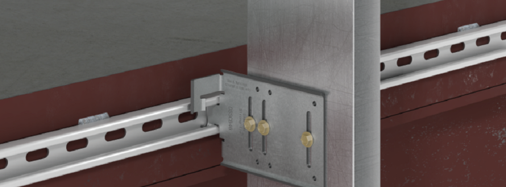
Structural engineers concerned with building envelopes are always looking for better solutions that help isolate the cladding from the primary structure in conditions where large building drift is a concern. Simpson Strong-Tie has an answer with a unique and innovative solution, the new DSSCB (drift strut sliding clip bypass).
Continue Reading
Q&A About CFS Designer™ Software

I recently had the pleasure of presenting a webinar with Rob Madsen, PE, of Devco Engineering on our CFS Designer software, “Increase Productivity in Your Cold-Formed Steel Design Projects.” The webinar took place on September 28, and a recording is available online on our training website for anyone who wasn’t able to join us. Viewing the recording (and completing the associated test) qualifies for continuing education units and professional development hours. The webinar covers how to use the CFS Designer software to design complex loading conditions for beams, wall studs, walls with openings, and stacked walls using cold-formed steel studs, tracks, built-up sections, and even custom shapes. We received some excellent questions during the webinar, but due to time constraints were only able to answer a few during the live webinar. Rob and I did get a chance to answer all the questions in a Q&A document from which I’d like to share some excerpts. The complete Q&A webinar list can be accessed here, or through the online recording.
Continue Reading

The Top 5 Helpful Tips for Using CFS Designer™ to Optimize Your Workflows
Back in April of last year, I had the opportunity to show how our new CFS Designer software could help structural engineers “go lean” in their design process by eliminating repetitive tasks (while still meeting required design standards, of course!). Since then, I’ve had the opportunity to visit with hundreds of engineers in person to teach them about CFS Designer and how it can help them improve and optimize their workflows. As a power user of the software, I want to share my top tips for letting CFS Designer help you save the maximum amount of time.
Continue Reading
DoD-Compliant CFS Wall Framing Design
Back in the year 2000, the U.S. Department of Defense (DoD) was charged with incorporating antiterrorism protective features into the planning, design and execution of its facilities. The main document developed to meet this requirement is the Unified Facilities Criteria “DoD Minimum Antiterrorism Standards for Buildings” (UFC 4-010-01). The current version was published in December 2018, with subsequent updates through Change 3 (May 2024). This document covers what is most commonly referred to as “blast” design.Continue Reading

Get There Quicker! How CFS Designer Can Help Speed Up Your Design Process
Did you know that Simpson Strong-Tie is celebrating its 60th birthday this year? We started out with one punch press and the ability to bend light-gauge steel. Then, one Sunday evening in the summer of 1956, Barclay Simpson’s doorbell rang and a request for our first joist hanger led us into the wood connector business. Since then, we’ve continued to grow that business by focusing on our engineering, research and development efforts. Some might say that nowadays we’re an engineering company that also happens to manufacture products, as evidenced by our focus on developing technology tools over the past few years such as web calculators, an updated website and design software. Our focus on technology, however, is really another aspect of our continued commitment to excellence in manufacturing and our application of the tenets of lean manufacturing.
Many of you may already be familiar with the idea of lean manufacturing made famous by Toyota in the early 2000s, along with the principles of continual improvement and respect for people. The concept of continual improvement is based on the idea that you can always make small changes to improve your processes and products. Although they were established in a manufacturing setting, these ideals ring very true for engineering as well; eliminate steps in your design process that don’t add any value to the final project and always be on the lookout for tools or techniques that can speed up your process. Thinking lean isn’t about cutting corners to get your result faster, it’s about mindfully getting rid of the steps that aren’t helping you and finding better ways of doing everyday tasks.
As structural engineers, we can find ourselves working on a variety of projects that lead us to perform repetitive calculations to check different conditions, such as varying parapet heights on the exterior of a building, or we may find ourselves working with an unfamiliar material, such as light-gauge or cold-formed steel (CFS), where we have to take some time away from design to review reference materials such as AISI S200-12 North American Standard for Cold-Formed Steel Framing. Wouldn’t it be great if there were a design tool that could help you complete your light-gauge projects more quickly, in complete compliance with current building codes?
It turns out that Simpson Strong-Tie offers a design tool called CFS Designer™ to help structural engineers improve their project design flow. This program gives engineers the ability to design light-gauge stud and track members with complex beam loading and span conditions according to building code specifications. What does that actually mean, though? Allow me to illustrate with an example of a design project.
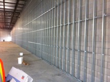
Let’s say you’re designing a building and part of your scope is the exterior wall framing, or “skin” of the building. You probably get sent some architectural plans that look something like this:
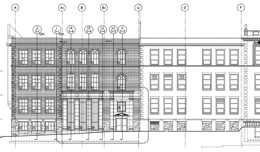
The architectural elevations will have wall section marks indicated for different framing situations. Two sample wall sections are shown in Figure 2.
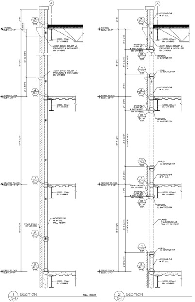
This building has several different wall section types that include door and window locations, varying parapet heights, diverse finish materials that need to meet different deflection criteria, and different connection points back to the base building. The traditional design calculation that you would need to run for one wall section might begin with a loading diagram similar to Figure 3 below.
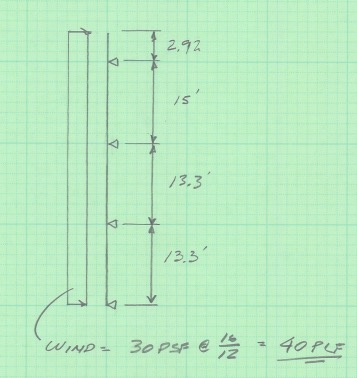
Once you have your loading diagram generated, you would need to use reference load tables or a computer analysis program to solve for the axial and moment demands, the reactions at the pinned supports, and the member deflections.
After you determine the demand loads, you would then need to select a CFS member with sufficient properties, and you may need to iterate a few times to find a solution that meets the load and deflection parameters. After you’ve selected a member with the right width, gauge and steel strength, you’ll need to select an angle clip that can handle the demand loads, as well as fasteners to connect the clip to the CFS stud and to the base building. You would also need to also check the member design to ensure that it complies with bridging or bracing requirements per AISI. Then, after all that, you’d have to repeat the process again for all of the wall section types for your project.
Just writing out that whole process took some time, and you can imagine that actually running the calculations takes quite a bit longer. I think we can all agree that the design process we’ve outlined is time-consuming, and here’s where using CFS Designer™ to streamline your design process can really help.
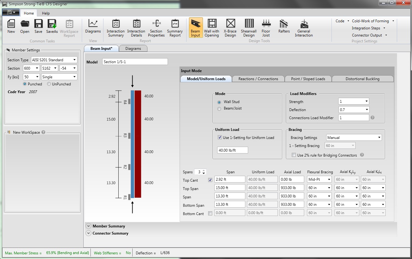
CFS Designer is a structural engineering design program that can automate many of the manual steps that are required in the design process. It has an easy-to-understand graphical user interface that allows you to input your project parameters within a variety of design modules from walls and beams, jambs and headers, X-brace walls, shearwalls, floor joists, and roof rafters. The program also enables the design of single stud or track members, built-up box-sections, back-to-back sections, and nested stud or track sections. Figure 5 shows an example of how you would input the same stud we looked at before into the program.
The program will generate the loading diagrams and complete calculation package for all of these different situations. And along with checking the member properties and deflection limits, CFS Designer will also check bridging and bracing requirements and provide connector solutions for the studs using tested and code-listed Simpson Strong-Tie products. Figure 6 shows an example of the summary output you would receive.
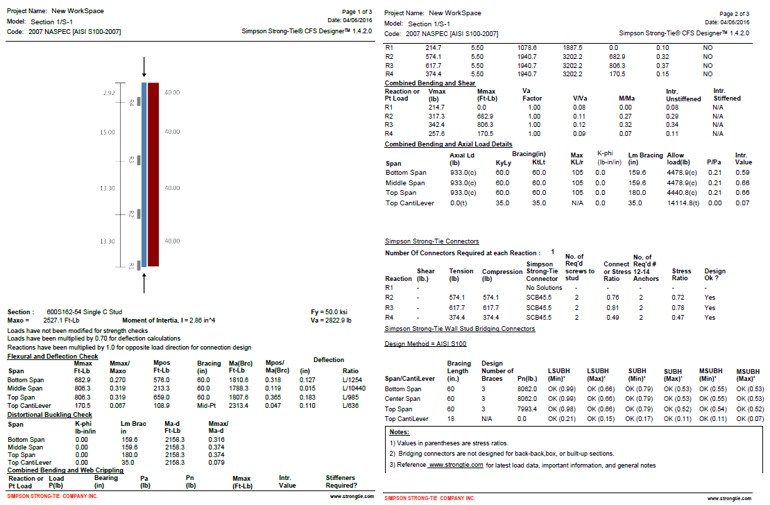
One unique part of the output is toward the center of the second page, under the heading “Simpson Strong-Tie Connectors.” This section summarizes the tension and compression loads at each reaction point and then shows a connector solution (such as the SCB45.5) along with the number of screws to the stud and the number of #12 sheet-metal screws to anchor back to the base building. Simpson Strong-Tie has developed and tested a full array of connectors specifically for CFS curtain-wall construction as well as for interior tenant improvement framing, which allows designers to select a connection clip straight out of a catalog without needing to calculate their own designs per the code. It’s just another way we’re helping you to get a little leaner!

The last part of the output shown in Figure 6 is titled “Simpson Strong-Tie Wall Stud Bridging Connectors.” It checks the bridging and bracing requirements per AISI S100 and selects a SUBH bridging connector, an innovative bridging solution developed by Simpson Strong-Tie that snaps into place and achieves design loads while only requiring one #10 screw to connect for 75% of applications.

You can download a free trial of CFS Designer™ and give it a test drive to see how much time it can save you on a design project. The trial version has almost full functionality, with the exception of not being able to print the output sheets. You can see purchasing information online, and you should always feel free to contact your local Simpson Strong-Tie engineering department with any questions you may have. I hope you are able to take advantage of this great tool to further improve your everyday design processes. We will be sure to keep you updated on our latest technology tools that help speed up the design process. If you’re using CFS Designer, we’d like to hear your thoughts about the program. Please share them in the comments below.