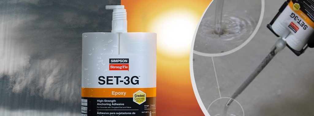
Modern construction schedules and conditions create a demand for solutions that can perform in a wide variety of environments. In the following post, Field Engineer Chris Johnson provides a rundown of different concrete and hole conditions for adhesive anchoring, the related design factors, and proper installation instructions and approved adhesive products for submerged anchorage.
Tag: uncracked concrete
Concrete Anchor Design for the International Building Code: Part 2
Designing “Alternative Materials”
Concrete anchor types whose designs are not addressed in the IBC or its Referenced Standards, or are specifically excluded from the scope of the Referenced Standard (ACI 318-11), may be recognized as Alternative Materials. Section 1909 of the 2012 IBC requires that “The strength design of anchors that are not within the scope of Appendix D of ACI 318, shall be in accordance with an approved procedure.” Section D.2.2 of ACI 318-11 lists some concrete anchor types that are considered “Alternative Materials” and specifically excludes these anchors from its scope. The list of “Alternative Material” anchors provided in this section is not, however, a comprehensive list.
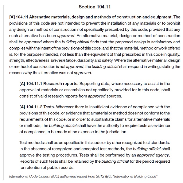
Section 104.11 of the 2012 IBC describes how the design professional must approach the design of Alternative Materials.
Section 104.11 provides the design professional with two options for the substantiation of the acceptable performance of an Alternative Material:
a. Research Reports. As described in the previous section (Design of Code Anchors), Research Reports are referenced as the primary source for the design and qualification of Alternative Materials. Research Reports for anchors are published by IAPMO UES or ICC-ES, both ANSI ISO 17065 accredited agencies. Publicly developed, majority-approved acceptance criteria are used to establish the test program and minimum performance requirements for an anchor type. Some Alternative Material anchor types have established acceptance criteria to which a product can be evaluated:
- Screw Anchors in Concrete (such as Simpson Strong-Tie® Titen HD®): ICC-ES AC193
- Headed Cast-in Specialty Inserts (such as Simpson Strong-Tie® Blue Banger Hanger®): ICC-ES AC446
- Powder- or Gas-Actuated Fasteners (such as Simpson Strong-Tie® PDPA and GDP): ICC-ES AC70
If Research Reports are used to substantiate an anchor’s performance, the design professional is bound by the design methodology and product limitations described in the Research Report.
b. Tests. If a Research Report is not available, and no acceptance criteria exists for a given anchor type, IBC Section 104.11 permits the use of tests performed in accordance with “recognized and accepted test methods” by an “approved agency” to substantiate performance. One example of an anchor type for which no acceptance criteria exists is:
- Helical Wall Ties (such as Simpson Strong-Tie® Heli-Tie™)
Cracked Concrete Determination
One of the many design considerations that the design professional must determine when designing either “Code Anchors” or anchors qualified as “Alternative Materials” is whether to consider the state of the concrete “cracked” or “uncracked.” The concrete state can significantly influence the anchor’s capacity. Neither the IBC nor ACI 318, Appendix D explicitly defines which applications should be categorized as “cracked” or “uncracked” concrete. The design professional must determine by analysis whether cracking will occur in the region of the concrete member where the anchors are installed. Absent an analysis to determine whether cracking will occur, the design professional may conservatively assume that the concrete state is “cracked.” With that said, there are two circumstances that require the design professional to design for “cracked” concrete:
a) Anchors in structures assigned to Seismic Design Categories C, D, E, or F (per 2012 IBC, Chapter 16) are required to be designed for “cracked” concrete unless the design professional can demonstrate that cracking does not occur at the anchor locations. The prequalification requirements of ACI 355.2 for mechanical anchors and ACI 355.4 for adhesive anchors include a test program that evaluates the performance of anchors in cracked concrete. Only anchors that have been tested and have passed the cracked concrete test program qualify for use in “cracked” concrete. The Research Report for a post-installed anchor (mechanical or adhesive) will clearly indicate whether it qualifies for use in “cracked concrete.”
b) Anchors located in a region of the concrete element where analysis indicates cracking at service level loading must be designed for “cracked” concrete (e.g. fr ≥ 7.5λ√f’c, ACI 318-11 eq. 9-10).
The design professional must consider additional factors that have the potential to result in concrete cracking in the region of anchorage. These factors include restrained shrinkage, temperature changes, soil pressure, and differential settlement. If no cracking is assumed in the region of the anchorage, the design professional should be able to justify that assumption.
Design Calculations
The design methodology in ACI 318 Appendix D is cumbersome. Calculations can be performed by hand using the design equations in Appendix D, inserting the substantiated data from an anchor manufacturer’s data tables or Research Reports to design with post-installed anchors. Designing with cast-in-place “Code Anchors” does not require additional data beyond what is included in ACI 318, Appendix D since these are “standard” anchors with standard design characteristics.
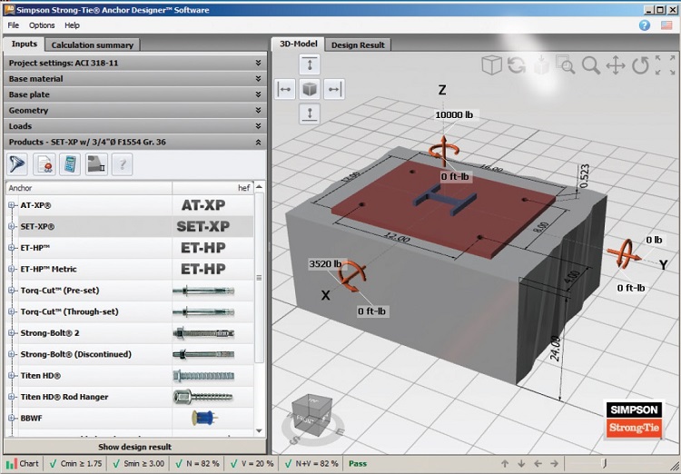
Performing hand calculations can be time-consuming, and for most design professionals is impractical due to the complexity of the design equations associated with multiple failure modes required to be considered. Design software, such as Simpson Strong-Tie® Anchor Designer™ Software for ACI 318, ETAG and CSA provides a fast, reliable method of calculating anchor performance for both cast-in-place and post-installed anchors. This software designs both “Code Anchors” and “Alternative Materials” for which an acceptance criteria exists.
Simpson Strong-Tie® Anchor Designer™ Software for ACI 318, ETAG and CSA is free and can be downloaded here.
New Simpson Strong-Tie Anchor Designer software
Remember back to the days when you used allowable stress design for designing anchorage to concrete? Once you had your design loads, selecting an anchor was quick and easy. The 1997 UBC covered the anchorage to concrete in less than two pages, so the calculation was painless. Post-installed anchors were even easier, since allowable loads were tabulated and you just needed to apply a couple of edge distance and spacing reductions.
Since the introduction of strength design provisions and the adoption of ACI 318 Appendix D, first in the 2000 IBC, designing code-compliant anchorage to concrete has become much more complex. At least once (and probably not more) armed with a pencil, calculator, and an eraser, most of us have set out to design a ‘simple’ anchorage to concrete connection using the Appendix D provisions. Several pages of calculations later (and hopefully with a solution to the problem), most of us, I imagine, came to realize that designing anchorages to concrete by hand required much more time and effort than we anticipated or could allocate time for. As a result, many of us probably created an Excel template to speed up the design process using built-in functions and some Visual Basic programming.
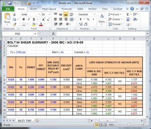
The question is: are you still using the template?
For me, the answer is an emphatic “NO”, mainly because the spreadsheet I created has limited capability given the complexity in adapting the design methodology to complex anchor layouts, changes to the design provisions with each new code edition, and the need to add/modify data each time a new post-installed anchor product is introduced.
The Anchorage to Concrete Challenge – How Do You Meet It?
We structural engineers here at Simpson Strong-Tie have a love/hate relationship with anchorage to concrete. Ever since the introduction of the strength design provisions in the 2000 IBC and ACI 318 Appendix D, anchorage to concrete has been a challenge for designers, building officials and manufacturers. SEAONC’s recent testing and the resulting code changes offer some relief to wood-frame designers for sill-plate anchor design at the edge of concrete, but many challenges remain.
With the increasing demand for high-density housing and urban infill projects, designers are now faced with anchoring multi-story wood-framed shear walls to relatively thin elevated concrete slabs (typically referred to as podium slabs). Overturning tension anchorage forces at the ends of shear walls in these projects can routinely be in the 40 kip range and even get as high as 60 kips or more.


