

The anchorage of nonstructural components like mechanical and electrical equipment is an important element of ensuring life safety that doesn’t always get the same attention as the structural engineering required for the building itself. The key standard that governs design loads is ASCE 7. This blog post explores updated equations in the newest edition of the standard, ASCE 7-22, specifically Chapter 13, which covers seismic design of nonstructural components. We’ll walk step by step through an example of anchoring a piece of equipment to a concrete slab inside a Risk Category IV building in a high seismic area.
Tag: anchor

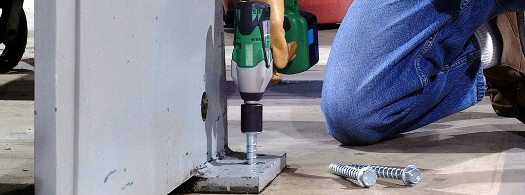
PAF, GAF or Pass? Part 1: A Guide to Selecting a Power-Actuated Fastening Solution
“PAF, GAF or Pass?” is a question that designers are often faced with when they need to attach wood or mechanical, electrical, or plumbing (MEP) fixtures to concrete, steel, or masonry structures, because there are several considerations to be made when deciding whether to utilize a direct-fastening solution or to “pass” and utilize a different attachment method. This is Part One of a two-part series discussing power–actuated fasteners and their applications. Before we get into the nitty-gritty, let’s define these acronyms and discuss how these types of fasteners work.

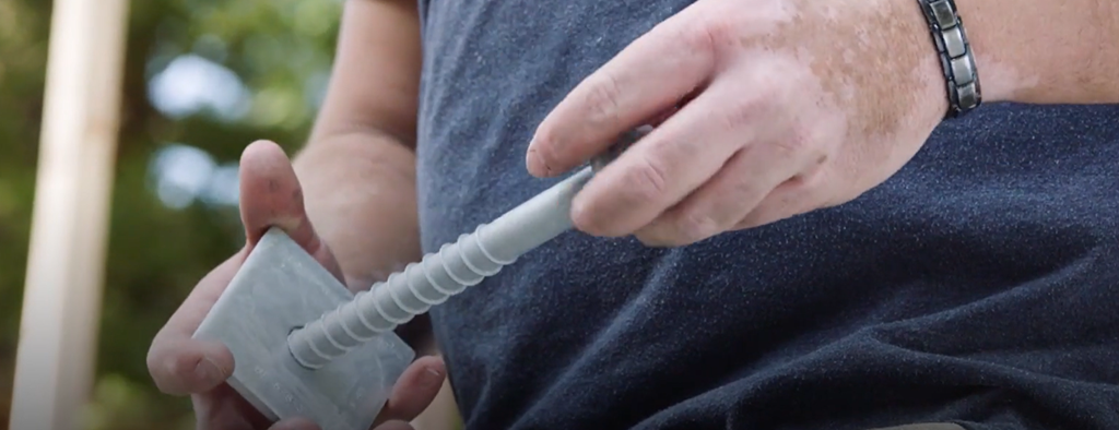
Anchor Anatomy 101: Heli-Tie™ Helical Wall Tie
This is the fourth Anchor Anatomy 101 blog post focusing on anchor systems. The goal of each post is to review anchor components, installation processes, and common applications to help you make informed anchor selection decisions based on your project’s unique requirements. The prior Anchor Anatomy 101 blog post focused on wedge type anchors. This blog post “drills down” into helical wall ties.

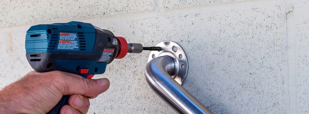
Anchor Anatomy 101: Strong-Bolt® 2 Wedge Anchor
We’re back today with our third Anchor Anatomy 101 blog post focusing on anchor systems. Each post is designed to clarify anchor components, installation processes, and common applications to help you make informed anchor selection decisions based on your project’s unique requirements. Our preceding post focused on adhesive anchor systems, while this post will look at wedge anchors.

Anchor Anatomy 101: SET-3G® Adhesive Anchoring System
Welcome to our second Anchor Anatomy 101 blog post focusing on anchor systems. Each post is designed to clarify anchor components, installation processes, and common applications to help you make informed anchor selection decisions based on your project’s unique requirements. Our first article focused on screw anchors; this blog looks at adhesive anchoring systems.
Anchor Anatomy 101: Titen HD® Concrete and Masonry Screw Anchors
Today’s blog post is the first in a series called “Anchor Anatomy 101.” Each post is designed to clarify anchor components, installation processes, and common applications to help you make informed anchor selection decisions based on your project’s unique requirements.
Concrete Results: The Titen Turbo™ Dust Channel Delivers Dependable Installations
Discover the innovation driving our Titen Turbo concrete screw anchors. In the following post, Ken Cho, Senior Product Engineer at Simpson Strong-Tie, explains how the patented dust channel design simplifies installations, eliminates frustrations and enhances overall efficiency. Revolutionize your concrete fastening projects with our latest offering — now also available in black!
Part II: A New Wood Construction Connectors Catalog for the New Year
We just released our updated Wood Construction Connectors catalog (C-C-2024) which features our product line that has a legacy that started in 1956. This year’s 372-page version begins with a colorful, attention-grabbing cover design and is packed inside with all the technical details that help people build safer, stronger structures. This blog is Part II of a two-part series highlighting this new catalog and the solutions inside it.
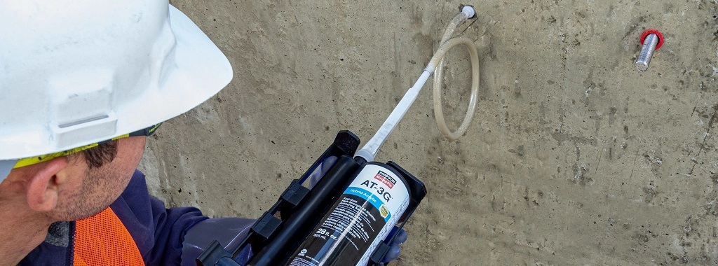
Introducing AT-3G™: Your high-strength cold-weather, fast-cure anchoring adhesive
In general, post–installed adhesive anchor design per ACI 318 Chapter 17 is relatively straightforward. In practice, however, post–installed anchorage can often become challenging because of fast–track project schedules, supply issues, ever-changing weather conditions, design conflicts/changes, or unexpected field conditions.
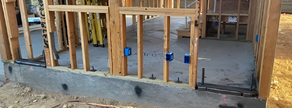
How to Accommodate Misplaced Shearwall Anchorage
For several years, the Simpson Strong-Tie Strong-Wall® research and development team has kicked around the idea of developing an “adapter” that would allow for field substitutions or accommodate misplaced Strong-Wall anchorage.