5 Steps to a Successful Soft-Story Retrofit

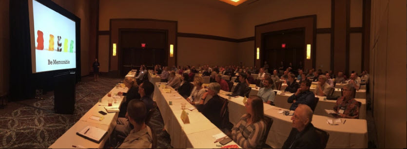
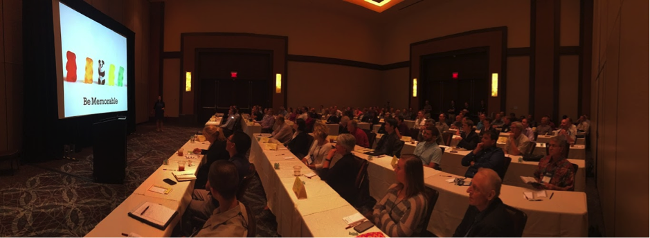
Last year, I gave a presentation at the annual National Council of Structural Engineers Associations (NCSEA) Summit in Orlando, Florida, titled “Becoming a Trusted Advisor: Communication and Selling Skills for Structural Engineers.” As this was a summit for the leaders of the structural engineers associations from across the country, I wasn’t sure how many people would find it valuable to spend their time learning about a very nontechnical topic. To my surprise and delight, the seminar ended up being standing-room only, and I was able to field some great questions from the audience about how they could improve their selling and communication skills. In the many conversations I had with the conference attendees after my presentation, the common theme was that engineers felt they needed more soft-skills training in order to better serve their clients. The problem, however, was finding the time to do so when faced with the daily grind of design work.

Structural Engineers In a Training for Seismic Retrofits
Presenting at the NCSEA Summit, I’m the tiny person in upper left hand corner.

When I started my first job as a design engineer at a structural engineering consulting firm straight out of school, I was very focused on improving and expanding my technical expertise. Whenever possible, I would attend building-code seminars, design reviews and new product solution presentations, all in an effort to learn more about structural engineering. What I found as I progressed through my career, however, was that no matter how much I learned or how hardworking I was, it didn’t really matter if I couldn’t successfully convey my knowledge or ideas to the person who really mattered most: the client.

Contractors discussing building plans with an engineer.

How can an engineer be most effective in explaining a proposed action or solution to a client? You have to be able to effectively sell your idea by understanding the needs of your client as well as any reasons for hesitation. The importance of effective communication and persuasion is probably intuitive to anyone who’s been on the sales side of the business, but not something that occurs naturally to data-driven folks like engineers. As a result of recent legislation in California, however, structural engineers are starting to be inundated with questions from a group of folks who have suddenly found themselves responsible for seismically upgrading their properties: apartment building owners in San Francisco and Los Angeles.

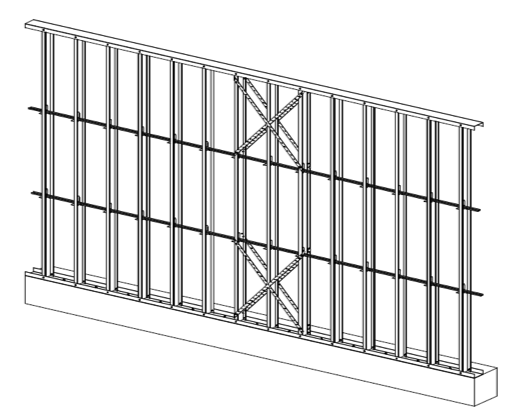
Imagine for a moment that you are a building owner who has received a soft-story retrofit notice under the City of Los Angeles’ Ordinance 183893; you have zero knowledge of structural engineering or what this term “soft-story” even means. Who will be your trusted advisor to help you sort it out? The City of Los Angeles Department of Building and Safety (LADBS) has put together a helpful mandatory ordinance website that explains the programs and also offers an FAQ for building owners that lets them know the first step in the process: hire an engineer or architect licensed in the state of California to evaluate the building.

Simpson Strong-Tie Structural Engineer Annie Kao at a jobsite.
Checking out some soft story buildings in Los Angeles. The Los Angeles Times has a great map tool.

I’ve had the opportunity to be the first point of contact for a building owner after they received a mandatory notice, because it turns out some relatives own an apartment building with soft-story tuck-under parking. Panicked by the notice, they called me looking to understand why they were being forced to retrofit a building that “never had any problems in the past.” They were worried they would lose rent money due to tenants needing to relocate, worried about how to meet the requirements of the ordinance and, most importantly, worried about how much it was going to cost them. What they really wanted was a simple, straightforward answer to their questions, and I did my best to explain the necessity behind retrofitting these vulnerable buildings and give an estimated time frame and cost that I had learned from attending the first Los Angeles Retrofit Resource Fair in April 2016. With close to 18,000 buildings in the cities of San Francisco and Los Angeles alone that have been classified as “soft-story,” this equates to quite a number of building owners who will have similar questions and be searching for answers.

To help provide an additional resource, Simpson Strong-Tie will be hosting a webinar for building owners in the Los Angeles area who have received a mandatory soft-story retrofit notice. Jeff Ellis and I will be covering “5 Steps to a Successful Retrofit” and helping to set a clear project path for building owners. The five steps that Simpson Strong-Tie will be recommending are:

  1. Understanding the Seismic Retrofit Mandate
  2. Partnering with Design Professionals
  3. Submitting Building Plans with the Right Retrofit Product Solutions
  4. Communicating with Your Building Tenants
  5. Completing Your Soft-Story Retrofit

We encourage you to invite any clients or potential clients to attend this informative webinar, which will lay the foundation for great communication between the two of you. As part of the webinar, we will be asking the building owners for their comments, questions and feedback so we can better understand what information they need to make informed decisions, and we will be sure to share these with the structural engineering community in a future post. By working together to support better communication and understanding among all stakeholders in retrofit projects, we will be well on our way to creating stronger and more resilient communities!

For additional information or articles of interest, there are several resources available:

Great ShakeOut Earthquake Drill 2016

The Great ShakeOut Earthquake Drill is an annual opportunity for people in homes, schools and organizations to practice what to do during earthquakes and improve their preparedness. In a post I wrote last October about the Great ShakeOut, I reminisced about the first earthquake I had to stop, drop and cover for – the Livermore earthquake in January, 1980. This year got me thinking about how our evacuation drills work.

At Simpson Strong-Tie, we use the annual Great ShakeOut drill to practice our building evacuation procedures. Evacuation drills are simple in concept – alarms go off and you exit the building. We have volunteer safety wardens in different departments who confirm that everyone actually leaves their offices. There are always a few people who want to stay inside and finish up a blog post. Once the building is empty and we have all met up in the designated meeting area, we do a roll call and wait for the all-clear to get back to work.

Several years ago the alarms went off. While waiting for the drill to end, we were concerned to see fire fighters arrive and rush into the building. Realizing this was not a drill, there were some tense moments of waiting. The fire chief and our president eventually walked out of the building and our president was yelling for one of our engineers. Turns out the engineer (who shall remain nameless) was cooking a chicken for lunch. Yes, a whole chicken. The chicken didn’t make it – I’m not sure what the guilty engineer had for lunch afterwards. At least we received extra evacuation practice that year. We aren’t allowed to cook whole chickens in the kitchen anymore.

Simpson Strong-Tie is helping increase awareness about earthquake safety and encouraging our customers to participate in the Great ShakeOut, which takes place next Thursday on October 20. It’s the largest earthquake drill in the world. More than 43 million people around the world have already registered on the site.

On October 20, from noon to 2:00 p.m. (PST), earthquake preparedness experts from the Washington Emergency Management Division and FEMA will join scientists with the Washington Department of Natural Resources and the Pacific Northwest Seismic Network for a Reddit Ask Me Anything – an online Q&A. Our very own Emory Montague will be answering questions. The public is invited to ask questions here. (Just remember that this thread opens the day before the event and not sooner.)

Emory Montague from Simpson Strong-Tie
Emory, ready to answer some seismic-related questions.

We’re also providing resources on how to retrofit homes and buildings, and have information for engineers here and for homeowners here.

Earthquake risk is not just a California issue. According to the USGS, structures in 42 of 50 states are at risk for seismic damage. As many of you know, we have done a considerable amount of earthquake research, and are committed to helping our customers build safer, stronger homes and buildings. We continue to conduct extensive testing at our state-of-the-art Tye Gilb lab in Stockton, California. We have also worked with the City of San Francisco to offer education and retrofit solutions to address their mandatory soft-story building retrofit ordinance and have created a section on our website to give building owners and engineers information to help them meet the requirements of the ordinance.

Last year, Tim Kaucher, our Southwestern regional Engineering Manager, wrote about the City of Los Angeles’s Seismic Safety Plan in this post. Since that time, the City of Los Angeles has put that plan into action by adopting mandatory retrofit ordinances for both soft-story buildings and non-ductile concrete buildings. Fortunately, California has not had a damaging earthquake for some time now. As a structural engineer, I find it encouraging to see government policy makers resist complacency and enact laws to promote public safety.

Participating in the Great ShakeOut Earthquake Drill is a small thing we can all do to make ourselves more prepared for an earthquake. If your office hasn’t signed up for the Great ShakeOut Earthquake Drill, we encourage you to visit shakeout.org and do so now.

Seismic Bracing Requirements for Nonstructural Components

Have you ever been at home during an earthquake and the lights turned off due to a loss of power?  Imagine what it would be like to be in a hospital on an operating table during an earthquake or for a ceiling to fall on you while you are lying on your hospital bed.

Continue Reading

Report Back from Nepal – Assessing Seismic Damage from April/May Earthquakes

As soon as news spread that 7.8-magnitude and 7.3-magnitude earthquakes struck Nepal in April and May of this year, earthquake structural engineering experts from our firm, Miyamoto International, hopped on planes from three countries to offer assistance. We do this in hopes that our expertise and technical advice might help stricken communities recover; help them to build better and ultimately help save lives.Continue Reading

Midrise of Steel

Guest blogger Jeff Ellis, engineering manager

The number of midrise structures constructed using light-frame cold-formed steel (CFS) certainly seems to be increasing each year. As with any material, there are benefits and challenges, especially in areas of moderate to high seismic risk. This post will discuss these as well as potential solutions.

Light-frame CFS midrise construction often uses ledger floor framing primarily to facilitate the load transfer detailing at the floor, tension anchorage (tie-downs or hold-downs) and compression chord studs or posts designed to resist the amplified seismic overturning loads. CFS framing is typically thin and singly symmetric.

Various CFS Construction Floor Framing Methods


Amplified Seismic Load

The AISI Lateral Design standard (AISI S213-07/S1-09) Section C5.1.2 requires that the nominal strength of uplift (tension) anchorage and the compression chord studs for shear walls resist the lesser of (1) the amplified seismic load or (2) the maximum load the system can deliver when the response modification coefficient, R, greater than 3. The amplified seismic load is defined as the load determined using the ASCE 7 seismic load combinations with the overstrength factor, Wo, which may be taken as 2.5 for CFS framed shear wall systems with flexible diaphragms.

Typically, the maximum the system can deliver to the uplift anchorage or chord studs is taken as the forces determined using the nominal shear strength of the shear wall assembly tabulated in the seismic shear wall table in S213 multiplied by 1.3. The S213 commentary accounts for the tabulated loads being based on Sequential Phased Displacement (SPD) rather than CUREE cyclic protocol and the degraded backbone curve. See the Structure magazine article that discusses the design of CFS framed lateral force-resisting systems.

Continuous Rod Tie-Down Systems

Light-framed CFS over three stories often use continuous rod tie-down systems rather than cold-formed steel hold-downs to resist shear wall overturning forces as they offer increased load capacity. Neglecting the dead load contribution, the amplified seismic load requirement for CFS shear walls using an R greater than 3 results in an 80% increase in the load used to size the continuous rod tie-down system compared to design level loads. For shear walls using an R greater than 3, it is important to note on the design drawings whether the uplift loads shown are ASD, LRFD, amplified ASD or amplified LRFD so the appropriate tie-down system may be designed.

Continuous Rod Tie-Down System Resisting Shear Wall Overturning Forces

Continuous rod tie-down systems are designed not only for strength, but also checked to ensure they do not deflect too much to cause the top of shear wall drift to exceed the code limit or to exceed the 0.20” vertical story deflection limit required by some jurisdictions and ICC-ES AC316. Take-up devices are used in CFS framed structures to take-up construction and settlement gaps that may occur.  AISI S200 Section C3.4.4 states that a gap of up to 1/8” might occur between the end of wall framing and the track. The vertical elongation of the continuous rod tie-down system includes rod elongation (PL/AE) and the take-up device deflection due to the seating increment and the deflection under load.

In addition, coordination is important in using continuous rod tie-down systems in CFS structures because the walls are often prefabricated offsite. An example is the consideration of the appropriate detail for the steel bearing plate installed at the floor sheathing in the story above to resist the uplift (tension) force from the story below.

One possible detail is to install the bearing plate in the bottom CFS track under all the CFS chord studs, but it’s important to ensure the bottom track flanges are deep enough to screw them to the stud flanges as the bearing plate can have a thickness of 1 ½” or more and typical tracks use 1 ¼” flanges. It is also important to ensure that the bearing plate width fits in the track. Another possible detail is to install the bearing plate under the CFS track under all the CFS chord studs.  However, then it must be cut into the floor sheathing and may cause the bottom track to be raised at the bearing plate. For this detail, the floor shear transfer must be detailed through the ledger into the CFS framing.

Continuous Rod Tie-Down System Steel Bearing Plate Coordination Issues

Concrete Tension Anchorage

The concrete tension anchorage is designed according to ACI 318 Appendix D using the continuous steel rod material and size in accordance with S213 to have the nominal strength to resist the lesser of the amplified seismic force or the maximum load the system can deliver. ACI 318-11 Section D.3.3.4.3 offers four force limits for design of concrete tension anchorage design in Seismic Design Category C through F:

(1)   The concrete nominal tension anchorage strength shall be greater than 1.2 times the ductile steel rod nominal tension anchorage strength

(2) The anchorage design strength shall be greater than the maximum tension force that can be delivered by a yielding attachment;

(3) The anchorage design strength shall be greater than the maximum tension force that can be delivered by a non-yielding attachment; and

(4) The anchorage design strength shall be greater than the amplified seismic force.

Typically either option (1) or (4) is used where (1) would lead to less concrete required than (4) if the bolt is efficiently sized while (4) would be required for such conditions as a vertical irregularity.  See the concrete anchorage and podium anchorage SE Blog posts for more details.

ACI 318-11 Section D.3.3.4.3 Anchorage Design Options

CFS Wall Stud Bracing

CFS studs are typically thin and singly symmetric and thus require bracing. AISI S211 (Wall Stud Design Standard) permits two types of bracing design that cannot be combined; sheathing based or steel based. There are limits on the stud axial strength when using sheathing braced design. It’s important to identify on the drawings that the sheathing braces the studs and another load combination must be used for the stud design.

2012 IBC Section 2211.4 requires stud bracing to be designed using either AISI S100 (North American Specification) or S211 (Wall Stud Design Standard). S100-07 Section D3.3 required nominal brace strength is to be 1% of the stud’s nominal compressive axial strength, but S100-12 Section D3.3 changes this to the required brace strength is to be 1% of the stud’s required compressive axial strength (demand load). In addition, D3.3 requires a certain stiffness for each brace. AISI S211 required brace strength is to be 2% of each stud’s required compressive axial strength for axially loaded studs and, for combined bending and axial loads, be designed for the combined brace force per S100 Section D3.2.2 and 2% of the stud’s required compressive axial strength.

There are two primary types of steel stud bracing systems: bridging and strap bracing. U-channel bridging extends through the stud punchouts and is attached to the stud with a clip, of which there are various solutions such as this post on Wall Stud Bridging.  Bridging bracing requires coordination with the building elements in the stud bay. It installs on one side of the wall, and does not bump out the wall sheathing. It also requires periodic anchorage to distribute the cumulative bracing loads to the structure for axially loaded studs often using strongback studs and does not require periodic anchorage for laterally loaded studs since the system is in equilibrium as the torsion in the stud is resisted by the U-channel bending.

Flat strap bracing is installed on either side of the wall and at locations other than the stud punchout. It bumps out the sheathing and requires periodic anchorage to distribute the cumulative bracing loads to the structure for axially and laterally loaded studs.

Beam

Strap and Block Bracing
Strap and Block Stud Bracing Anchored Periodically to Structure Using Strongbacks

Beam2

Bridging and Clip Bracing Anchored Periodically to Structure Using Strongbacks
Bridging and Clip Bracing Anchored Periodically to Structure Using Diagonal Strap Bracing

Light-frame cold-formed steel construction has been used successfully for many projects, but there are challenges  that must be addressed to ensure code compliance and desired performance. Some beneficial resources for designing CFS structures are the SEAOC 2012 IBC Structural/Seismic Design Manual Volumes 1 and 2 and the Cold-Formed Steel Engineers Institute’s (CFSEI) website where you can find technical notes and design guides.

What have been some of your observations or challenges in designing cold-formed steel midrise structures?

Ignore Seismic Requirements When Wind Controls?

Prior to joining Simpson Strong-Tie, my career involved the design of projects in California’s San Francisco Bay Area. When designing the primary lateral force resisting system, I would have several pages of seismic base shear calculations and, oh yeah, a one- or two-line calculation of the wind forces – just to show that seismic governed. There was no need for complete wind analysis, since the seismic design and detailing requirements were more restrictive. Of course, building components such as parapets, cladding or roof screens needed a wind design. Unfortunately, when wind appears to control, meeting the seismic requirements is not so simple.

Continue Reading