


Today the NEES-Soft project has begun testing the steel Simpson Strong-Tie® Strong Frame® Special Moment Frame as a retrofit option for soft-story buildings at the NEES outdoor shake table facility at UC San Diego. The testing is focused on validating the FEMA P-807 design procedure, which attempts to create a least-cost retrofit solution by only retrofitting the garage areas of problem buildings.Continue Reading
Category: Testing/R&D
Simpson Strong-Tie is constantly testing and innovating.

Steel Moment Frame Beam Bracing
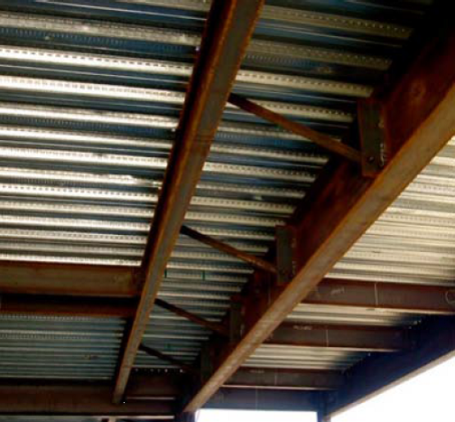
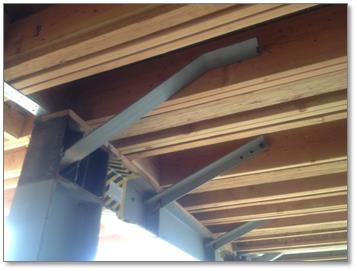
In a previous blog post on soft-story retrofits, I briefly discussed beam bracing requirements for moment frames. This week, I wanted to go into more detail on the subject because it’s important to understand that a typical steel moment frame requires lateral beam bracing to develop its full moment capacity. Figure 1 below shows two common methods of beam bracing. While on the surface determining beam bracing requirements may not appear complicated, there are several items that could prove it to be more challenging than you might think, especially when steel moment frames are used in light frame construction.
Figure 1: Steel Beam Bracing
Before going into beam bracing in steel moment frames, it is important to discuss the behavior of a simply supported beam under gravity load. Short beams (Lb < Lp)[3], might not require bracing to achieve the full plastic moment of the beam section. However, when a beam is long (Lb > Lr) and without bracing, the beam can twist or buckle out-of-plane. Figure 2 illustrates these two behaviors along with the case where the beam length is somewhere in between the two (e.g., Inelastic lateral torsional buckling). In addition, if beam sections are non-compact, flange local buckling (FLB) or web local buckling can occur prior to reaching the beams full plastic moment.

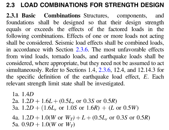
Are the Load Combinations Balanced?
In April’s post about the Omega Factor, one commenter asked of the 1.2 increase allowed by ASCE 12.4.3.3, “Why do they allow a stress increase for allowable combinations? Seems unconservative for steel now that they have essentially balanced the ASD capacity with LRFD.”
To be honest, I have never spent much time analyzing which design methodology was more or less conservative. If I was designing with wood I would use ASD, and if it was with concrete I would use LRFD. Steel was strictly ASD early on in my design career, but LRFD usage grew. The question about balance made me curious. Are the load combinations balanced?

Of course, just comparing the load combinations would be meaningless. We know the LRFD combinations result in higher design forces. But those higher forces are compared to higher design strengths. So we need to normalize things.

Open Front Structure Wind Pressure Design
We received a request from Martin H., one of our blog readers, to discuss the method for determining roof wind pressures on an open front agricultural building. The inquiry was regarding clarification on analyzing the roof pressure when a combined external and interior pressure exists and whether these are additive.
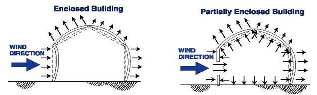
As can be seen in the above illustrations, the net design pressure on the roof is the sum of the uplift on the exterior surface and the uplift on the interior surface from any internal pressure. ASCE 7 provides a method for determining this pressure. Specifically, ASCE 7-22 will be used for the remainder of this post. Assuming the three remaining sides of the open front structure are walls without openings, the building will be classified as partially enclosed by the definitions of Section 26.2.
ASCE 7-22 provides for two methods for determining the Main Wind Force Resisting System (MWFRS) wind loads for partially enclosed buildings, the Directional Procedure in Chapter 27, and the Envelope Procedure in Chapter 28.
When using the Directional Procedure, the net wind load is calculated using the following equation:
P = qGCp – qi(GCpi)
When using the Envelope Procedure, the net wind load is calculated using the following equation:
P = qh[(GCpf) – (GCpi)]
In each of these equations, the first portion determines the pressure on the exterior surface, and the second portion determines the pressure on the interior surface. So the variable for calculating the internal pressure is the internal pressure coefficient GCpi.
The internal pressure coefficient is provided in Table 26.11-1 based on three different categories of building enclosure.
|
Enclosure Classification |
(GCpi) |
| Open Buildings |
0.00 |
| Partially Enclosed Buildings |
+0.55 -0.55 |
| Enclosed Buildings |
+0.18 -0.18 |
Table 26.11-1
In the case of an open front structure, it is assumed that the partially enclosed internal pressure coefficient must be used. This coefficient is 3x greater than when the building envelope is classified as enclosed. Use of this higher coefficient in the design will account for the interior pressure on the underside of the roof combined with the exterior pressure.
MWFRS versus C&C
Another somewhat related question: to what level loads should the roof anchorage forces be calculated, MWFRS or C&C (Component and Cladding)? I have often been asked this question, and wrote a Technical Note published by CFSEI (Cold-Formed Steel Engineers Institute) in July 2009.
What are your thoughts?
– Sam
What are your thoughts? Visit the blog and leave a comment!
So, What’s Behind A Structural Connector’s Allowable Load? (Holdown Edition)
This is Part 1A of a four-part series I’ll be doing on how connectors, fasteners, anchors and cold-formed steel systems are load rated.
I envisioned doing a four-part series on how connectors, fasteners, anchors, and cold-formed steel are load rated. After writing the first installment on connectors, I realized that connectors are a bit more complicated, since the testing and evaluation for joist hangers (or similar devices) is different than testing for holdown devices. And I wanted to discuss holdowns. So without belaboring the apology for my numbering system, this will be part 1A of the series – still discussing wood connectors, but focusing on holdowns and some of the unique requirements in their load rating.
AC155, Acceptance Criteria for Hold-Downs (Tie-Downs) Attached to Wood Members, was first developed in 2005 to better address boundary conditions, deflection limits, and wood post limits. Prior to AC155, holdowns were evaluated based on testing on a steel jig with a safety factor of 3.0 and an NDS bolt calculation. Deflection at the allowable load was simply reported so that it was available for use in design, but there was not a deflection limit that affected the load rating.

In the steel jig setup shown, the jig keeps the holdowns stationary while the rectangular bar underneath the holdowns is pushed downward to simulate an uplift force. This was (and still is) an effective method of testing the capacity of the steel body of a holdown, but it does not tell you a lot about the deflection of the holdown when installed on a wood member. Since story-drift is such a critical component to shearwall performance and the deflection of holdowns has a significant effect on the total drift, this needed to be address in the holdown test standard.
Continue Reading

So, What’s Behind A Structural Connector’s Allowable Load?
This is Part 1 of a four-part series I’ll be doing on how connectors, fasteners, anchors and cold-formed steel systems are load rated.
Today I did my presentation for the WoodWorks webinar on Testing and Product Evaluation of Products for Wood-framed Construction. We covered a lot of material regarding code requirements for using alternate materials or construction methods, how testing and evaluation criteria are developed, and some specifics on several Acceptance Criteria (AC’s) that are commonly used for connector evaluations. We also discussed some specific testing requirements, so I thought it would be timely to discuss some of those issues in this week’s blog post.
So, how are structural connectors for light frame wood construction load rated? What’s behind the allowable loads information published in Simpson Strong-Tie literature or wood connector evaluation reports? These are things that you might find yourself wondering while driving to the office or jobsite, or on a Sunday afternoon while enjoying your favorite iced tea or barley-based beverage.
The short answer is: testing, calculations, and of course, sound engineering judgment.
Continue Reading