A while back, we posted about how structural engineers can use social media like Facebook, Twitter and LinkedIn. We discussed how structural engineers can use LinkedIn as a tool to find out more about industry news. While that is one way to use LinkedIn, another way to get even closer to the pulse of your industry is to join industry-specific LinkedIn groups.
LinkedIn groups are places within LinkedIn that allow professionals to share content, post or view job openings, network, and help establish key opinion leaders in a particular industry.
If you are new to LinkedIn, it can be challenging to find all of the LinkedIn groups that you may want to join. We compiled a list of structural engineering LinkedIn groups that can help you get started:
American Society of Civil Engineers (ASCE): This group was initially formed to allow networking between engineers. It has now grown to over 200,000 members and includes other professionals who work in the industry. Since this is a large group, there are more focused sub-groups that you can also join. We recommend using the ASCE group for general information.
ASCE: Structural Engineering: This is a sub-group of ASCE. The members of this LinkedIn group are mainly structural engineers. This is a good place for discussion and asking for feedback on work-related topics.
American Concrete Institute: This is a great group for structural engineers who work with concrete. You can connect not just with engineers, but also with professionals in the concrete production, design and construction industries.
SEAOC-Structural Engineers Association of California: If you are a structural engineer in California, we highly recommend this group. If you are interested in structural and seismic engineering, this is the group to join.
NCSEA: The National Council of Structural Engineers Associations (NCSEA) is a great group to join to get industry information, find resources including webinars, and hear about local industry events and meetings.
While there are a lot more LinkedIn groups, we hope that the ones we have shared are useful for you. What LinkedIn groups do you recommend? Let us know in the comments below.
A firewall is a term that is used in the construction industry to describe a fire-resistive-rated wall or fire-stop system, which is an element in a building that separates adjacent spaces to prevent the spread of fire and smoke within a building or between separate buildings. A firewall is actually one of three different types of walls that can be used to prevent the spread of fire and smoke.
Types of fire-resistive-rated walls:
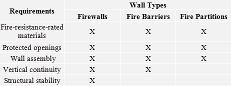
The three types of fire-resistive-rated walls are firewalls, fire barriers and fire partitions. They are listed in order from the most stringent requirements to the least. A firewall is a fire-resistive-rated wall having protected openings, which restricts the spread of fire and extends continuously from the foundation to or through the roof with sufficient structural stability under fire conditions to allow collapse of construction on either side without collapse of the wall. A fire barrier is a fire-resistive-rated wall assembly of materials designed to restrict the spread of fire which continuity is maintained. A fire partition is a vertical assembly of materials designed to restrict the spread of fire in which openings are protected. Each type has varying requirements and the table below displays some of the differences between them.
What are some of the typical uses of each type of fire-resistive wall?
As the requirements for each type of wall vary, so do the uses. Typical uses of each are as follows:
Firewalls – party walls, exterior walls, interior bearing walls
Fire barriers – shaft enclosures, exit passageways, atriums, occupancy separations
Fire partitions – corridor walls, tenant space walls, sleeping units within the same building
How do you determine whether your wood building design needs a firewall?
The 2024 International Building Code (the IBC, or “the Code” in what follows), which is adopted by most building departments in the United States, is the resource we are using in this discussion. (As a side note, it’s possible your city or county has supplemental requirements, and it is best to contact your local building department for this information up front.)
To determine your fire-resistive wall requirements, review these chapters in the 2024 IBC:
Chapter 3, Identify Occupancy Group – typically Section 310 (“Residential Group”) for wood construction
Chapter 5, Select Construction Type – Section 504, Table 504.3
Chapter 6, Determine Fire-Resistive Rating Requirements – Table 601, typically Type III wood-constructed buildings require a two-hour fire separation for the exterior bearing walls
What are typical fire-resistive wall designs?
Information for one-hour, two-hour designs, etc. can be found in tables 721.1(2) and 721.1(3) of the Code provide information to obtain designs that meet the rating requirements (in hours) for your building, including the walls and floor/roof systems. The GA-600 is another reference that the Code allows if the design is not proprietary.
How do I know whether the structural attachments I specify for the wall and roof assemblies meet the Code requirement?
Once the wall or floor/roof assembly design is selected, the Designer must ensure that the components of the wall do not reduce the fire rating. The Code requires that products which pierce the membrane of the assemblies at a hollow location undergo a fire test to ensure they meet the requirements of the design. ASTM E814 and ASTM E119 are the standards governing the fire tests for materials and components of the fire-resistive wall. There are several criteria that the component in the assembly must meet: a flame-through criterion, a change-in-temperature criterion and a hose-stream test.
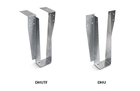
Simpson Strong-Tie has created the DHU, DGT, DGHT hanger for use with typical two-hour fire-resistive walls for wood construction. The DHU hanger has passed the ASTM E814 testing and can be used on a fire-resistive wall of 2×4 or 2×6 constructions and up to two 5/8″ layers of gypsum board. The DHU and DHUTF have both an F (Fire) and a T (Temperature) rating.
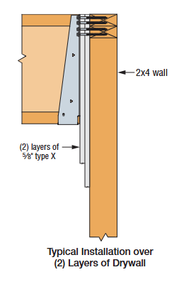
The DHU/DHUTF hanger has two options, a face-mount version (DHU) and a top-flange version (DHUTF). The hanger doesn’t require any cuts or openings in the drywall, which ensures reliable performance; no special inspection is required. To install the hanger, gypsum board must first be installed in a double or single layer, at least as deep as the hanger. For installation, apply a two-layer strip of Type X drywall along the top of the wall, making the base layer a wider strip (bottom edge is 12″ or more below the face layer, depending on jurisdiction). Then install ¼” x 3½” Simpson Strong-Tie Strong-Drive® SDS screws through the hanger and into top plates of the wall. Since the hanger is more eccentric than typical, the top plates of the wall must be restrained from rotation. The SSP clip can be used for restraint, but the design may not require it if there is a sufficient amount of resistance already in place, such as sheathing, a bearing wall above, or a party wall as determined by the designer. See the photos and installation illustration below for guidance or visit our website for further information.
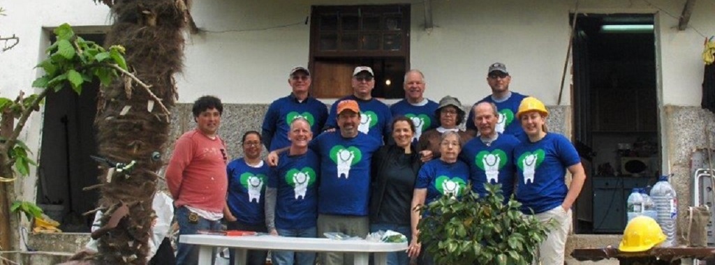
Five Simpson Strong-Tie employees had the opportunity to participate in a week-long Habitat for Humanity build in the small town of Amarante, Portugal, in late April. The company decided to allocate the funds for the CWP to Habitat’s Global Village program, allowing these employees to help renovate and remodel the older home of a widowed mother (Doña Margarida Ribiero) and daughter (Sonia) living in the Portuguese countryside.
Five Simpson Strong-Tie employees had the opportunity to participate in a week-long Habitat for Humanity build in the small town of Amarante, Portugal, in late April. The group was originally scheduled to work on a Habitat project in Nepal late last year as part of Habitat’s Jimmy and Rosalynn Carter Work Project (CWP), but following the signing of a new constitution and civil unrest in the country, the project was canceled.Continue Reading
Editor’s Note: This is a republished blog post with an introduction by Jeff Ellis.
This is definitely an attention-grabbing headline! At the National Earthquake Conference in Long Beach on May 4, 2016, Dr. Thomas Jordan of the Southern California Earthquake Center gave a talk which ended with a summary statement that the San Andreas Fault is “locked, loaded and ready to go.”
The LA Times and other publications have followed up with articles based on that statement. Temblor is a mobile-friendly web app recently developed to inform homeowners of the likelihood of seismic shaking and damage based on their location and home construction. The app’s creators also offer a blog that provides insights into earthquakes and have writtene a post titled “Is the San Andreas ‘locked, loaded, and ready to go’?” This blog post delves a bit deeper to ascertain whether the San Andreas may indeed be poised for the “next great quake” and is certainly a compelling read. Drop, cover and hold on!
Volkan and I presented and exhibited Temblor at the National Earthquake Conference in Long Beach last week. Prof. Thomas Jordan, USC University Professor, William M. Keck Foundation Chair in Geological Sciences, and Director of the Southern California Earthquake Center (SCEC), gave the keynote address. Tom has not only led SCEC through fifteen years of sustained growth and achievement, but he’s also launched countless initiatives critical to earthquake science, such as the Uniform California Earthquake Rupture Forecasts (UCERF), and the international Collaboratory for Scientific Earthquake Predictability (CSEP), a rigorous independent protocol for testing earthquake forecasts and prediction hypotheses.
In his speech, Tom argued that to understand the full range and likelihood of future earthquakes and their associated shaking, we must make thousands if not millions of 3D simulations. To do this we need to use the next generation of super-computers—because the current generation is too slow! The shaking can be dramatically amplified in sedimentary basins and when seismic waves bounce off deep layers, features absent or muted in current methods. This matters, because these probabilistic hazard assessments form the basis for building construction codes, mandatory retrofit ordinances, and quake insurance premiums. The recent Uniform California Earthquake Rupture Forecast Ver. 3 (Field et al., 2014) makes some strides in this direction. And coming on strong are earthquake simulators such as RSQsim (Dieterich and Richards-Dinger, 2010) that generate thousands of ruptures from a set of physical laws rather than assumed slip and rupture propagation. Equally important are CyberShake models (Graves et al., 2011) of individual scenario earthquakes with realistic basins and layers.
But what really caught the attention of the media—and the public—was just one slide
Tom closed by making the argument that the San Andreas is, in his words, “locked, loaded, and ready to go.” That got our attention. And he made this case by showing one slide. Here it is, photographed by the LA Times and included in a Times article by Rong-Gong Lin II that quickly went viral.
Believe it or not, Tom was not suggesting there is a gun pointed at our heads. ’Locked’ in seismic parlance means a fault is not freely slipping; ‘loaded’ means that sufficient stress has been reached to overcome the friction that keeps it locked. Tom argued that the San Andreas system accommodates 50 mm/yr (2 in/yr) of plate motion, and so with about 5 m (16 ft) of average slip in great quakes, the fault should produce about one such event a century. Despite that, the time since the last great quake (“open intervals” in the slide) along the 1,000 km-long (600 mi) fault are all longer, and one is three times longer. This is what he means by “ready to go.” Of course, a Mw=7.7 San Andreas event did strike a little over a century ago in 1906, but Tom seemed to be arguing that we should get one quake per century along every section, or at least on the San Andreas.
Could it be this simple?
Now, if things were so obvious, we wouldn’t need supercomputers to forecast quakes. In a sense, Tom’s wake-up call contradicted—or at least short-circuited—the case he so eloquently made in the body of his talk for building a vast inventory of plausible quakes in order to divine the future. But putting that aside, is he right about the San Andreas being ready to go?
Because many misaligned, discontinuous, and bent faults accommodate the broad North America-Pacific plate boundary, the slip rate of the San Andreas is generally about half of the plate rate. Where the San Andreas is isolated and parallel to the plate motion, its slip rate is about 2/3 the plate rate, or 34 mm/yr, but where there are nearby parallel faults, such as the Hayward fault in the Bay Area or the San Jacinto in SoCal, its rate drops to about 1/3 the plate rate, or 17 mm/yr. This means that the time needed to store enough stress to trigger the next quake should not—and perhaps cannot—be uniform. So, here’s how things look to me:
The San Andreas (blue) is only the most prominent element of the 350 km (200 mi) wide plate boundary. Because ruptures do not repeat—either in their slip or their inter-event time—it’s essential to emphasize that these assessments are crude. Further, the uncertainties shown here reflect only the variation in slip rate along the fault. The rates are from Parsons et al. (2014), the 1857 and 1906 average slip are from Sieh (1978) and Song et al. (2008) respectively. The 1812 slip is a model by Lozos (2016), and the 1690 slip is simply a default estimate.
So, how about ‘locked, generally loaded, with some sections perhaps ready to go’
When I repeat Tom’s assessment in the accompanying map and table, I get a more nuanced answer. Even though the time since the last great quake along the southernmost San Andreas is longest, the slip rate there is lowest, and so this section may or may not have accumulated sufficient stress to rupture. And if it were ready to go, why didn’t it rupture in 2010, when the surface waves of the Mw=7.2 El Major-Cucapah quake just across the Mexican border enveloped and jostled that section? The strongest case can be made for a large quakeoverlapping the site of the Great 1857 Mw=7.8 Ft. Teton quake, largely because of the uniformly high San Andreas slip rate there. But this section undergoes a 40° bend (near the ‘1857’ in the map), which means that the stresses cannot be everywhere optimally aligned for failure: it is “locked” not just by friction but by geometry.
A reality check from Turkey
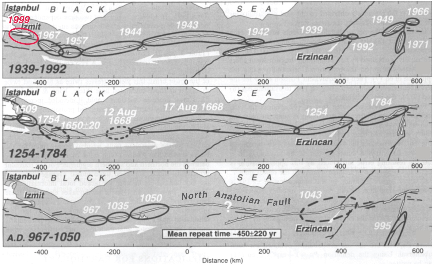
Sometimes simplicity is a tantalizing mirage, so it’s useful to look at the San Andreas’ twin sister in Turkey: the North Anatolian fault. Both right-lateral faults have about the same slip rate, length, straightness, and range of quake sizes; they both even have a creeping section near their midpoint. But the masterful work of Nicolas Ambraseys, who devoured contemporary historical accounts along the spice and trade routes of Anatolia to glean the record of great quakes (Nick could read 14 languages!) affords us a much longer look than we have of the San Andreas.
The idea that the duration of the open interval can foretell what will happen next loses its luster on the North Anatolian fault because it’s inter-event times, as well as the quake sizes and locations, are so variable. If this 50% variability applied to the San Andreas, no sections could be fairly described as ‘overdue’ today. Tom did not use this term, but others have. We should, then, reserve ‘overdue’ for an open interval more than twice the expected inter-event time.
This figure of North Anatolian fault quakes is from Stein et al. (1997), updated for the 1999 Mw=7.6 Izmit quake, with the white arrows giving the direction of cascading quakes. Even though 1939-1999 saw nearly the entire 1,000 km long fault rupture in a largely western falling-domino sequence, the earlier record is quite different. When we examined the inter-event times (the time between quakes at each point along the fault), we found it to be 450±220 years. Not only was the variation great—50% of the time between quakes—but the propagation direction was also variable.
However, another San Andreas look-alike, the Alpine Fault in New Zealand, has a record of more regular earthquakes, with an inter-event variability of 33% for the past 24 prehistoric quakes (Berryman et al., 2012). But the Alpine fault is straighter and more isolated than the San Andreas and North Anatolian faults, and so earthquakes on adjacent faults do not add or subtract stress from it. And even though the 31 mm/yr slip rate on the southern Alpine Fault is similar to the San Andreas, the mean inter-event time on the Alpine is longer than any of the San Andreas’ open intervals: 330 years. So, while it’s fascinating that there is a ‘metronome fault’ out there, the Alpine is probably not a good guidepost for the San Andreas.
If Tom’s slide is too simple, and mine is too equivocal, what’s the right answer?
I believe the best available answer is furnished by the latest California rupture model, UCERF3. Rather than looking only at the four San Andreas events, the team created hundreds of thousands of physically plausible ruptures on all 2,000 or so known faults. They found that the mean time between Mw≥7.7 shocks in California is about 106 years (they report an annual frequency of 9.4 x 10^-3 in Table 13 of Field et al., 2014; Mw=7.7 is about the size of the 1906 quake; 1857 was probably a Mw=7.8, and 1812 was probably Mw=7.5). In fact, this 106-year interval might even be the origin of Tom’s ‘once per century’ expectation since he is a UCERF3 author.
But these large events need not strike on the San Andreas, let alone on specific San Andreas sections, and there are a dozen faults capable of firing off quakes of this size in the state. While the probability is higher on the San Andreas than off, in 1872 we had a Mw=7.5-7.7 on the Owen’s Valley fault (Beanland and Clark, 1994). In the 200 years of historic records, the state has experienced up to three Mw≥7.7 events, in southern (1857) and eastern (1872), and northern (1906) California. This rate is consistent with, or perhaps even a little higher than, the long-term model average.
So, what’s the message
While the southern San Andreas is a likely candidate for the next great quake, ‘overdue’ would be over-reach, and there are many other fault sections that could rupture. But since the mean time between Mw≥7.7 California shocks is about 106 years, and we are 110 years downstream from the last one, we should all be prepared—even if we cannot be forewarned.
Sarah Beanland and Malcolm M. Clark (1994), The Owens Valley fault zone, eastern California, and surface faulting associated with the 1872 earthquake, U.S. Geol. Surv. Bulletin 1982, 29 p.
Kelvin R. Berryman, Ursula A. Cochran, Kate J. Clark, Glenn P. Biasi, Robert M. Langridge, Pilar Villamor (2012), Major Earthquakes Occur Regularly on an Isolated Plate Boundary Fault, Science, 336, 1690-1693, DOI: 10.1126/science.1218959
James H. Dietrich and Keith Richards-Dinger (2010), Earthquake recurrence in simulated fault systems, Pure Appl. Geophysics, 167, 1087-1104, DOI: 10.1007/s00024-010-0094-0.
Edward H. (Ned) Field, R. J. Arrowsmith, G. P. Biasi, P. Bird, T. E. Dawson, K. R., Felzer, D. D. Jackson, J. M. Johnson, T. H. Jordan, C. Madden, et al.(2014). Uniform California earthquake rupture forecast, version 3 (UCERF3)—The time-independent model, Bull. Seismol. Soc. Am.104, 1122–1180, doi: 10.1785/0120130164.
Robert Graves, Thomas H. Jordan, Scott Callaghan, Ewa Deelman, Edward Field, Gideon Juve, Carl Kesselman, Philip Maechling, Gaurang Mehta, Kevin Milner, David Okaya, Patrick Small, Karan Vahi (2011), CyberShake: A Physics-Based Seismic Hazard Model for Southern California, Pure Appl. Geophysics, 168, 367-381, DOI: 10.1007/s00024-010-0161-6.
Julian C. Lozos (2016), A case for historical joint rupture of the San Andreas and San Jacinto faults, Science Advances, 2, doi: 10.1126/sciadv.1500621.
Tom Parsons, K. M. Johnson, P. Bird, J.M. Bormann, T.E. Dawson, E.H. Field, W.C. Hammond, T.A. Herring, R. McCarey, Z.-K. Shen, W.R. Thatcher, R.J. Weldon II, and Y. Zeng, Appendix C—Deformation models for UCERF3, USGS Open-File Rep. 2013–1165, 66 pp.
Seok Goo Song, Gregory C. Beroza and Paul Segall (2008), A Unified Source Model for the 1906 San Francisco Earthquake, Bull. Seismol. Soc. Amer., 98, 823-831, doi: 10.1785/0120060402
Kerry E. Sieh (1978), Slip along the San Andreas fault associated with the great 1857 earthquake, Bull. Seismol. Soc. Am.,68, 1421-1448.
Ross S. Stein, Aykut A. Barka, and James H. Dieterich (1997), Progressive failure on the North Anatolian fault since 1939 by earthquake stress triggering, Geophys. J. Int., 128, 594-604, 1997, 10.1111/j.1365-246X.1997.tb05321.x
This week’s post was written by Kevin Gobble of Habitat for Humanity. Kevin is the Program Manager for Habitat for Humanity’s new Habitat Strong initiative. Kevin has spent over 22 years in residential construction building energy-efficient, high-performing home, and has consulted with several sustainable building programs on ways to develop their own best practices. As a third-generation builder, he has knowledge in the field of residential building science and has furthered his education to include many industry certifications — NARI Certified Remodeler, NAHB Certified Green Professional, RESNET Certified Green Rater, BPI Building Analyst, FORTIFIED evaluator, and Level 1 Infrared Thermography — while working directly with industry partners to focus on cost-effective construction solutions. Kevin has built and remodeled numerous homes to high-performance standards as certified by various building programs, including his latest project for himself: converting a condemned historic property in Atlanta to EarthCraft House Platinum.
In a previous blog post, we discussed the background of the Habitat Strong program. Habitat Strong promotes the building of resilient homes that are better equipped to withstand natural disasters in every region of the country. This program uses IBHS FORTIFIED Home™ standards and works well within Habitat’s model of building affordable, volunteer-friendly homes.Continue Reading
Who likes red rust? No one I know! How do we avoid corroding of fasteners? Corrosion can be controlled or eliminated by providing a corrosion-resistant base metal or a protective finish or coating that is capable of withstanding the exposure environment. When fasteners get corroded, they not only look bad from outside but can also lose their load capacity. To ensure continued fastener performance, we have to control for corrosion. This blog focuses on evaluating the corrosion resistance of the fasteners.
What does the building code specify?
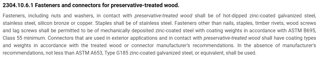
For use in preservative-treated wood, the IBC-2024 specifies fasteners that are hot-dipped galvanized, stainless steel, silicon bronze or copper. Section 2304.10.6.1 of IBC-2024 (Figure 1) covers fastener and connector requirements for preservative-treated wood (chemically treated wood). While chemically treated wood is part of the corrosion hazard, it is not the whole corrosion hazard. Weather exposure, airborne chemicals and other environmental conditions contribute to the corrosion hazard for metal hardware. In addition, the main issue with the code-referenced requirements for fasteners and connectors used with preservative-treated wood is that not all preservative treatments deliver the same corrosion hazard and not all fasteners can be hot-dip galvanized.
Figure 1: Section 2304.10.6.1 IBC-2024.
What if we want to use an alternative base material or coating for fasteners?
How do we evaluate the corrosion resistance of the alternative material or coating? The codes do not provide test methods to evaluate alternate materials and coatings. However, the International Code Council–Evaluation Service (ICC-ES) developed acceptance criteria to evaluate alternative coatings that are not code recognized for use in different environments. The purpose of acceptance criteria ICC-ES AC257, Acceptance Criteria for Corrosion-Resistant Fasteners and Evaluation of Corrosion Effects of Wood Treatment Chemicals, is twofold: (1) to establish requirements for evaluating the corrosion resistance of fasteners that are exposed to wood-treatment chemicals, weather and salt corrosion in coastal areas; and (2) to evaluate the corrosion effects of wood-treatment chemicals. In this blog post, we will concentrate on the evaluation of corrosion resistance of fasteners. The criteria provide a protocol to evaluate the corrosion resistance of fasteners where hot-dip galvanized fasteners serve as a performance benchmark. The fasteners evaluated by these criteria are nails or screws that are exposed directly to wood-treatment chemicals and that may be exposed to one or more corrosion accelerators like high humidity, elevated temperatures, high moisture or salt exposure.
The fasteners may be evaluated for any of the four exposure conditions:
Exposure Condition 1 with high humidity. This test can be used to evaluate fasteners that could be exposed to high humidity. Typical applications that fall under this category are treated wood in dry-use applications.
Exposure Condition 2 with untreated wood and salt water. This test can be used to evaluate fasteners that are above ground but exposed to coastal salt exposure.
Exposure Condition 3 with chemically treated wood and moisture. This test covers all the general construction applications.
Exposure Condition 4 with chemically treated wood and salt water. Typical applications include coastal construction applications.
Depending on the exposure condition being used for fastener evaluation, the fasteners are installed in wood that could be either chemically treated or untreated. Then the wood and the fasteners are placed in the chamber and artificially exposed to the evaluation environment. Two types of test procedures are to be completed for exposure condition 2 through 4. The purpose of these tests is not to predict the corrosion resistance of the coatings being evaluated, but to compare them to fasteners with the benchmark coating (ASTM A153, Class D) in side-by-side exposure to the accelerated corrosion environment.
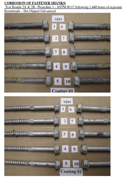
ASTM B117 Continuous Salt-Spray Test
ASTM B117 is a continuous salt-spray test. For Exposure Condition 3, distilled water is used instead of salt water. The fasteners are continuously exposed to either moisture or salt spray in this test, and the test is run for about 1,440 hours after which the fasteners are evaluated for corrosion. This is an accelerated corrosion test that exposes the fasteners to a corrosive attack so the corrosion resistance of the coatings can be compared to a benchmark coating (hot-dip galvanized).
ASTM G85, Annex A5
The second test is ASTM G85, Annex A5 which is a cyclic test with alternate wet and dry cycles. The cycles are 1-hour dry-off and 1-hour fog alternatively. This is a cyclic accelerated corrosion test and relates more closely to real long-term exposure. This test is more representative of the actual environment than the continuous salt-spray test. As in the ASTM B117 test, the fasteners along with the wood are exposed to 1,440 hours, after which the corrosion on the fasteners is evaluated and compared to fasteners with the benchmark coating.
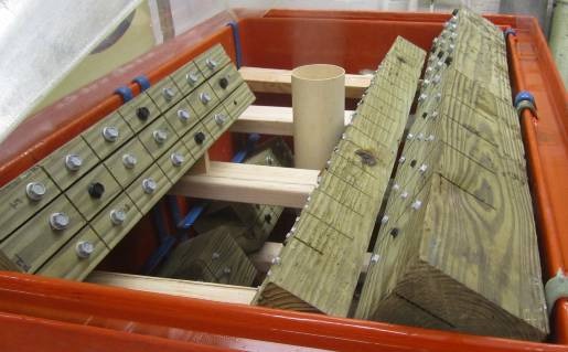
Test Method and Evaluation
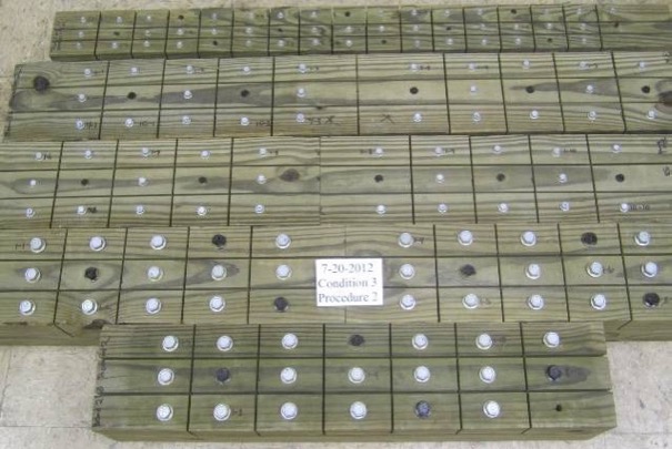
The test process involves installing 10 benchmark fasteners along with 10 fasteners for each alternative coating being evaluated. The fasteners are arranged in the wood with a spacing of 12 times the fastener diameter between the fasteners. A kerf cut is provided in the wood between the fasteners to isolate the fasteners as shown in Figure 2 and to ensure elevated moisture content in the wood surrounding the fastener shank. The moisture and retention levels of the wood are measured, and the fasteners are then installed in the chamber as shown in Figure 3 and exposed to the designated condition. The test is run for the period specified, after which the fasteners are removed, cleaned and compared to the benchmark for corrosion evaluation. Figure 4 shows the wood and fastener heads after 1,440 hours (60 days). The heads and shanks of the fasteners are visually graded for corrosion in accordance with ASTM D610. If the alternate coating performs equivalent to or better than the benchmark coating — that is, if the corrosion is no greater than in the benchmark — then the coating has passed the test and can be used as an alternative to the code-approved coating. Figure 5 shows the benchmark and alternative fasteners that are removed from the chamber after 1,440 hours.
As you can see, the alternative coatings have to go through extended and rigorous testing and evaluation as part of the approval process before being specified for any of the fasteners. Some alternative coatings provide even better corrosion resistance than the code recognized options. Sometimes, also, the thickness of these alternative coatings may be smaller than the thick coating required for hot-dip galvanized parts. Some of our coatings, such as the Double-Barrier coating, the Quik Guard® coating and the ASTM B695 Class 55 Mechanically Galvanized have gone through this rigorous testing and have been approved for use in preservative-treated wood in the AC257 Exposure Conditions 1 and 3. In addition, these coatings have been qualified for use with chemical retentions that are typical of AWPA Use Category 4A – General Ground Contact. No salt is found in AC257 Exposure Conditions 1 and 3. Please refer to our Fastener Systems Catalog, C-F-2025, pages 17–18 for corrosion recommendations and pages 19–20 for additional information on coatings.
What do you look for specifically in a fastener? Do you have a preference for a certain coating type or color? Let us know in the comments below!
Figure 2: Fasteners with different coatings along with the benchmark, installed in wood and separated by kerf cuts.Figure 3: Fasteners and wood pieces installed in the chamber.Figure 4: Snap shot of fasteners in ASTM B117 chamber after 1,440 hours.Figure 5: Fasteners after 1,440 hours of exposure, removed from the wood, cleaned and compared to benchmark. Coating 1 – Benchmark (Hot- dip Galvanized) and Coating 2 (Alternative coating).
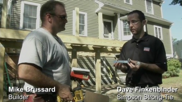
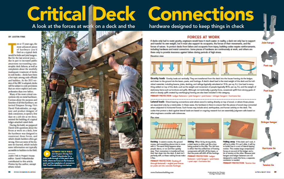
We’re partnering with folks at Fine Homebuilding on a video series on how to build a deck that is code compliant and that highlights the critical connections of a deck. This series is called Ultimate Deck Build 2016. The video series comprises five videos that walk professionals through the recent code changes for the key connections of a deck.
The series features David Finkenbinder, P.E., a branch engineer for Simpson Strong-Tie who is passionate about deck codes and safety. He offers information on load resistance and the hardware that professionals can use at the crucial connections to make a deck code compliant. “This was a great opportunity to collaborate with the team at Fine Homebuilding, to communicate the connections on a typical residential deck and the role that they serve to develop a strong deck structure,” said David. “These same connections would also likely be common in similar details created by an Engineer, when designing a deck per the International Building Code (IBC).”
The videos are being released every Wednesday during the month of March and feature the following deck connections:
Ledger Connection: This is the primary connection between a deck and a house. David tells the Fine Homebuilding team about various code- compliant options for attaching a deck ledger to a home.
Beam and Support Posts: David explains how connectors at this critical point can prevent uplift and resist lateral and downward forces. He also discusses footing sizes and post-installation anchor solutions.
Joists: This video reviews proper joist hanger installation and the benefits of installing hurricane ties between the joists and the beams. David goes into common joist hanger misinstallations, such as using the wrong fasteners or using a joist hanger at the end of a ledger.
Guardrail Posts: David reviews the different ways that you can attach a guardrail post so as to resist an outward horizontal load.
Stairs: David explains code-compliant options for attaching stringers to a deck frame.
Make sure to watch the series and let us know what you think. For more information, Fine Homebuilding has created an article titled “Critical Deck Connections.”
(Please note: this article is member-only/subscription content, so to read it you’ll need to either subscribe online or pick up the April/May issue of Fine Homebuilding.)
This week we’re blogging about corrosion, and we’re not talking about rusting of the soul — we’re talking about oxidation of steel.
In 2014, we reviewed our corrosion protection recommendations for new catalog publications. In doing so, we realized that we could facilitate selection of hardware and fasteners if our Corrosion Resistance Classifications for treated wood were linked to common design conditions described in the codes. We made some revisions to our Corrosion Resistance Classifications during that exercise. This blog post talks about those changes and some current related activity in the wood treatment industry.
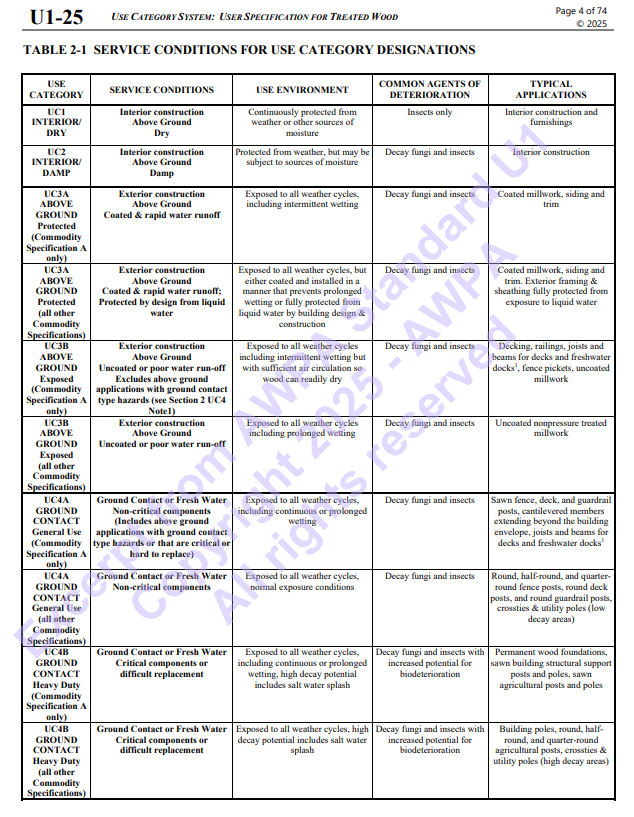
The common design conditions for corrosion-resistant wood construction include the wood materials with associated treatments and the environmental corrosion agents. The American Wood Protection Association (AWPA), which is an ANSI-accredited consensus standards organization, publishes the code-referenced standard, AWPA U1-15 Use Category System: User Specifications for Treated Wood.
When you specify treated wood, this is the standard that defines the appropriate treatment chemicals and chemical retentions depending on the exposure condition and bio-hazard, which the AWPA has summarized into a Use Category (UC) system. Figure 1 is a clip from the AWPA web site that gives a glimpse at the UC system. As the UC rating increases from UC1 to UC5, the chemical retention increases because the bio-hazard is increasing. Corrosion hazards are directly related to the combination of treatment chemical, treatment chemical retention and use environment.
Figure 1. Summary of AWPA Use Category System https://awpa.com/images/2025/U1-25_excerpt.pdf
The AWPA UC system does not include environmental corrosion agents. As a result, we had to separately integrate those with treatment chemical effects as we developed the corrosion resistance classifications.
Finally, one more evaluation system had to be addressed: the exposure conditions of ICC-ES AC257 — Corrosion Resistant Fasteners and Evaluation of Corrosion Effects of Wood Treatment Chemicals. In the end, we developed Corrosion Resistance Classifications that considered the AWPA Use Categories, environmental corrosion agents and the ICC-ES AC257 exposure conditions.
Some of you may be thinking that we have not mentioned another aspect of corrosion — galvanic corrosion. Galvanic corrosion results when metals with dissimilar electrical potentials are placed in contact in the presence of an electrolyte (water). We’ll take up galvanic corrosion in a subsequent blog post.
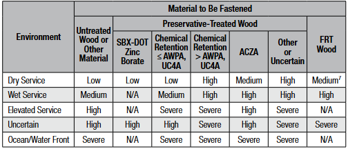
Our basic Corrosion Resistance Classification table is shown in Figure 2.
Figure 2. Corrosion Resistance Classifications (from C-F-2025, p. 18, or strongtie.com)
The ratings shown in the table — Low, Medium, High and Severe — refer to the corrosion resistance of Simpson Strong-Tie coating systems and base metals. An example of a coating system that is rated “Low” is paint or electro-galvanized zinc. An example of a material rated for “Severe” corrosion conditions is Type 316 stainless steel.
To use the Corrosion Resistance Classifications table, find the Environment, then move to the correct column in the Material to Be Fastened section; identify a rating. Then look in the companion table labeled “Corrosion Resistance Recommendations” to identify a coating or base metal that is appropriate for your project. Be sure to read the table notes to the Corrosion Resistance Classifications for exceptions and limitations. We implemented this system to simplify product selection. Let’s take a look at each aspect that contributes to the Corrosion Resistance Classifications table.
Environment
The environment captures the moisture, atmospheric conditions and other elements that affect corrosion rate. “Dry Service” usually means an interior space with low moisture content or dampness. No liquid water is present in this sort of environment. The absence of moisture limits the electrochemical reaction needed to produce what we see as corrosion. “Wet Service” usually means exterior exposure and involves liquid water as direct exposure or condensation and wood moisture contents that can exceed air-dry conditions and may be temporary or persist for prolonged periods. We incorporated environmental agents with the “Elevated Service and Ocean/Waterfront” conditions. These environmental agents include fumes, acid rain, airborne salinity, etc. The “Uncertain Environment” was included for the Designer who does not know the corrosive conditions in service.
Material Being Fastened
Here we distinguish between clean materials and wood treated with chemicals — wood preservatives or fire-retardant chemicals (FRT). Untreated softwoods used for framing are generally not significantly corrosive. This does not include cedars and redwood, which are a special case. Cedars tend to be corrosive and particularly prone to staining when fastened with carbon steel hardware and fasteners. As a result, our recommendations for untreated softwoods are generally a function of the environment — moisture, weather exposure and corrosion agents such as salt spray, sulfur or fertilizer fumes and acid rain are all examples.
Some treatment chemicals do not significantly increase the corrosion hazard. These are the SBX-DOT treatment chemicals (inorganic boron and borate treatments). These are not typically used in exterior environments or for high-moisture conditions. The preservatives are not chemically bound to the wood and they can leach out under exposure to liquid moisture, which would leave the wood unprotected. The corrosion hazard attendant to these chemicals is similar to that of untreated wood and the codes permit the use of bare carbon steel in contact with wood treated with these chemicals (IBC2024, Section 2304.10.6.1 and IRC2025, Section R304.3.1 (exception 3)).
Most of the waterborne chemicals in common use contribute to an elevated corrosion hazard. Some of the common wood treatment chemicals include formulations of alkaline copper quaternary (ACQ), copper azole (CA), ammoniacal copper zinc arsenate (ACZA) and micronized copper azole (MCA). The AWPA UC system defines the exposure conditions for each Use Category as well as the chemical retention required to prevent a decay failure. The MCA formulations are alternatives to those specified in the code-referenced standard through the evaluation report process and are not standardized by the AWPA. The evaluation report process for wood preservatives requires the submission of evidence in compliance with ICC-ES AC326 — Proprietary Wood Preservative Systems — Common Requirements for Treatment Process, Test Methods and Performance.
We realize that UC4A is a general-use ground-contact condition, and further, it is the maximum necessary specification for treated wood in many building applications. The Simpson Strong-Tie Corrosion Resistance Classifications recognize that the corrosion hazard of treatment chemical retentions for UC4A in Wet Service is a “Medium” corrosion condition (with the exception of ACZA, which is rated “High” in Wet Service). This means that carbon steel products with sufficient corrosion resistance (e.g., ZMAX, double barrier coating, etc.) can be used in these conditions assuming no other corrosion-causing agents are present.
On the other hand, the moisture conditions and treatment chemical retentions are elevated in UC4B and UC4C, and there is also a potential for salt exposure, which further escalates the corrosion hazard. In these conditions, stainless steel is generally recommended for connectors and fasteners as the best material for mitigating the corrosion risk.
The last column in the Corrosion Resistance Classifications table is devoted to FRT wood. Fire-retardant treatment chemicals are proprietary and are deemed to meet the requirements of the codes through the evaluation report process (ICC-ES AC66 — Acceptance Criteria for Fire-Retardant-Treated Wood). We cannot evaluate the corrosion resistance of hardware to all of the FRT formulations. However, we have reviewed most of the FRT evaluation reports for corrosion information. The corrosion effects of FRT chemicals, like preservative treatment chemicals, are minimized in dry-service conditions because the electrochemical reaction cannot progress or is slowed without an electrolyte. The Corrosion Resistance Classifications reflect that information. The Designer should always follow the FRT evaluation reports in addition to considering our recommendations.
It is important to note that the Corrosion Resistance Classifications are not associated with specific applications. Rather, the ratings are based on the integrated effects of the environment and the wood treatment where the chemical retentions given in the AWPA Use Category system play an important role in the ratings. This makes it relatively straightforward to select hardware that is adequate for a design environment.
Changes to the AWPA U1 Standard and Effects on Corrosion Resistance Classifications
As noted here and in the online JLC article, wood preservative chemicals can achieve compliance with the codes by either of two methods:
The product is a generic product (e.g., ACQ-D or CA-B) and is listed in the AWPA U1 standard; or
The product has an evaluation report obtained by submitting evidence in accordance with ICC-ES AC326 — Proprietary Wood Preservative Systems — Common Requirements for Treatment Process, Test Methods and Performance.
You may be aware that the AWPA is revising its code-referenced standard, AWPA U1-15, Use Category System: User Specification for Treated Wood. The consensus process is ongoing and is not complete. However, AWPA member chemical companies (Viance, Koppers, and Arch) have placed information in the market. In parallel with the AWPA, ICC-ES has modified AC326 to reflect the changes ongoing in the AWPA U1 standard. Simpson Strong-Tie has been in contact with the AWPA, other industry associations and industry professionals to understand the potential effects on metal hardware of the AWPA U1 and ICC-ES AC326 revisions.
The proposed revisions to the AWPA U1 standard modify the definitions for UC3A, UC3B, UC4A, UC4B and UC4C. The most important revisions are to UC3B and UC4A. The new definition for applications in UC3B suggests that beams and joists in decks and docks may have bio-hazards that exceed the UC3B assumptions, while the new UC4A definition will include above-ground applications with ground- contact hazards. The revised AWPA U1 standard will be published in the May–June 2016 time frame; AWPA U1-16 will be included in the 2018 codes.
The revision to ICC-ES AC326 also modifies the definitions for UC3B, UC4A and UC4B. ICC-ES AC326 has an implementation date of July 2016, which will cause some changes to specifications this summer. Micronized copper azole (MCA) formulations are the most common treatment chemicals that will be affected by this action.
Revisions to the Use Category definitions are being driven by two issues:
Wood treated for UC3 is sometimes used in near-ground applications where the bio-hazard is more like UC4.
Under-treatment compromises the margin of safety to bio-hazards, which can lead to decay failures.
Rather than revisit the retention specifications in AWPA U1 standard, the AWPA is modifying the definitions for the Use Categories that are involved, and that language has been carried into ICC-ES AC326 to ensure that the two systems are consistent with each other. The result of changes to the Use Category definitions will likely cause some specifications to change from UC3B to UC4A or from UC4A to UC4B. The main effects will likely be to specifications in eastern and southern states, where there may be more chemical in the wood to meet retention specifications.
The Simpson Strong-Tie Corrosion Resistance Classifications make specific reference to the corrosive levels of environmental conditions and the chemical treatment and retentions of the AWPA Use Categories, not to applications. As a result, the AWPA U1 revisions and the parallel changes to ICC-ES AC326 will not necessitate a change in our corrosion recommendations, because the chemical retentions for each Use Category have not changed. However, your hardware specifications could change for typical applications depending on the Use Category of the treated wood in your project. Our information suggests that this issue is still not settled within the industry, and we will pass along information as we learn it.
Simpson Strong-Tie is currently preparing new catalogs for the coming year and will be updating the corrosion information in those publications and our website. We’re interested in your experience with our Corrosion Resistance Classifications and whether you have suggestions for how we might make the content more useful to you.
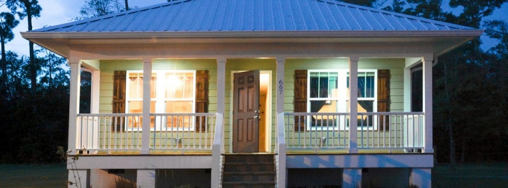
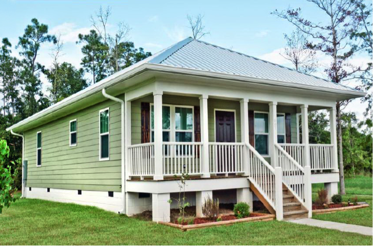
You’re probably already familiar with Habitat for Humanity, a nonprofit builder of simple, decent and affordable homes for low-income families around the world. According to builderonline.com, they were the 15th-largest builder in the country in 2015 when ranked by number of closings. Simpson Strong-Tie has been an official national partner with Habitat for Humanity since 2007, making contributions of cash and products exceeding $2.5 million in that time, and Simpson Strong-Tie employees have spent hundreds of hours building homes and training local Habitat affiliates.
We know from working on Habitat houses that they tend to be well built. There were newspaper articles about Habitat houses performing better than neighboring houses in Hurricane Andrew. In an effort to better benefit the homeowners they serve, Habitat has recently started a formal program to build even better, code-plus homes that could stand up to local hazards and document the methods used during construction. The name of this new program is Habitat Strong. Simpson Strong-Tie is proud to be a major sponsor of the program.
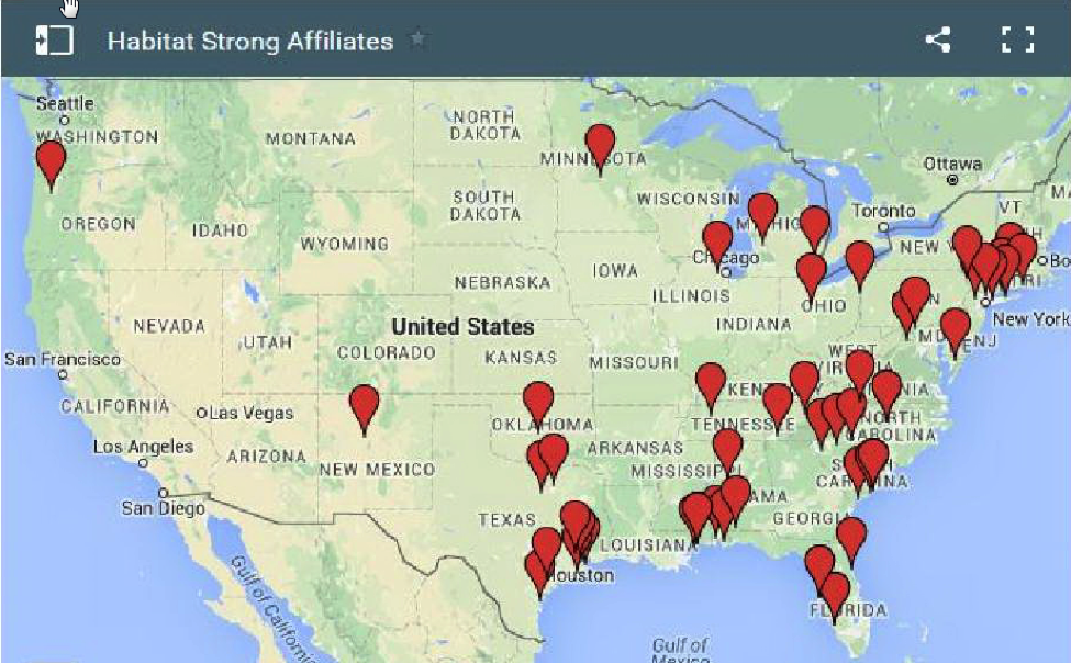
Habitat Strong actually began as a pilot project funded by Travelers Insurance that built 20 disaster-resistant homes in Alabama, Mississippi, New York and Connecticut. The success of that project convinced Habitat of the importance of building stronger, more resilient homes in all parts of the country. Starting from those regional hurricane-inspired efforts, the Habitat Strong program is now being used by more than 48 affiliates throughout the country, as shown on this map.
According to Habitat for Humanity, “The Habitat Strong program is designed to promote the building of homes that are more durable, resilient, and physically stronger. The need for stronger homes has become increasingly apparent, and through Habitat Strong’s fortified codes-plus building practices, we are able to strengthen homes’ building envelopes, which enable[s] them to better withstand natural disasters in every region of the country. This program was developed specifically for the Habitat model to be affordable and volunteer-friendly, while offering benefits to partner families that will last for years to come. Based on these principles, we believe that building homes Habitat Strong is the right thing to do!”
Habitat for Humanity has established a set of construction standards for Habitat Strong that are based on the Insurance Institute for Business & Home Safety® (IBHS) FORTIFIED Home™ program. The FORTIFIED program is a scientifically developed, systems-based incremental approach for creating stronger, safer homes. There are three levels of FORTIFIED Home™ designations: Bronze, Silver and Gold. Each level builds upon measures at the preceding level to increase the disaster resistance of the home. You can take a look at the FORTIFIED Home standards on the IBHS website at www.disastersafety.org.
There are now three separate sets of FORTIFIED Home™ standards: Hurricane, High Wind & Hail, and High Wind. In general, the three levels consist of the following:
Bronze:
Strengthen roof deck fastening by using 8d ring-shank nails in a closer-than-normal nailing pattern.
Apply a secondary water barrier to the roof deck so there will still be protection from water damage even if the roof covering is blown off.
Install a roof covering that is rated for high winds and, if appropriate, hail forces.
Prune nearby trees to prevent damage to the home during a wind event.
Silver:
Complete all requirements for Bronze.
Brace gable ends over 4′ tall and ensure they are sheathed with a minimum thickness of wood structural panel.
Anchor wood frame chimneys to the roof structure.
Anchor attached structures, such as porches and carports, from the roof to the foundation.
Gold:
Complete all requirements for Silver.
Provide a continuous load path for wind forces from the roof to the foundation. In a normal 115-mph wind zone, the load path is to be designed for at least 140 mph.
Provide a garage door that is rated for high winds.
Habitat for Humanity is recommending to their affiliates that homes built in coastal areas be built to the IBHS Gold standard for hurricanes, and those built in inland areas be built at a minimum to the Bronze or Silver standards for high winds. The Habitat homes that meet the Bronze or Silver standards will be certified as Habitat Strong. Habitat homes that are built to the Gold standard will be certified as Habitat Strong+.
Simpson Strong-Tie is proud to be assisting Habitat for Humanity with Habitat Strong. In January, we hosted a training for Texas affiliates that was offered by Habitat and IBHS staff at our Houston training facility. We also donated connectors for a demonstration home at Michigan State University that we helped design.
We know many of you visit our website on a regular basis for product and technical information and to use our software, calculator tools and other web apps. If you haven’t visited strongtie.com recently, it has a new look and several new features, including enhanced search and browsing and a mobile-friendly design. Here are some of the new features and site improvements:
Update-to-date product information: If there is a new code report, catalog or product you will be able to find that information on our new website first. It has the latest product and technical information while retaining the same features and information you expect.
Enhanced search and browsing: You can now search for our products based on specific product attributes. Our enhanced search capabilities allow you to explore our collection of products by applying filters so you can quickly and easily browse and find the products that you are looking for.
Mobile-friendly: Our new site has a responsive design that allows you to view the site in any format. From large desktops to mobile devices, you can view our site in the office or while on the go.
Enhanced Visuals: We have added new and improved photographs, illustrations and graphics so that you can see our products in greater detail.
We hope the new website better serves your design and technical needs. If you have any suggestions, comments or feedback, please email us at web@strongtie.com or leave a comment below.
We use cookies on this site to enhance your user experience. By clicking "I AGREE" below, you are giving your consent for us to set cookies. Privacy PolicyI AGREE
Privacy & Cookies Policy
Privacy Overview
This website uses cookies to improve your experience while you navigate through the website. Out of these cookies, the cookies that are categorized as necessary are stored on your browser as they are essential for the working of basic functionalities of the website. We also use third-party cookies that help us analyze and understand how you use this website. These cookies will be stored in your browser only with your consent. You also have the option to opt-out of these cookies. But opting out of some of these cookies may have an effect on your browsing experience.
Necessary cookies are absolutely essential for the website to function properly. This category only includes cookies that ensures basic functionalities and security features of the website. These cookies do not store any personal information.
Any cookies that may not be particularly necessary for the website to function and is used specifically to collect user personal data via analytics, ads, other embedded contents are termed as non-necessary cookies. It is mandatory to procure user consent prior to running these cookies on your website.


 next generation of super-computers—because the current generation
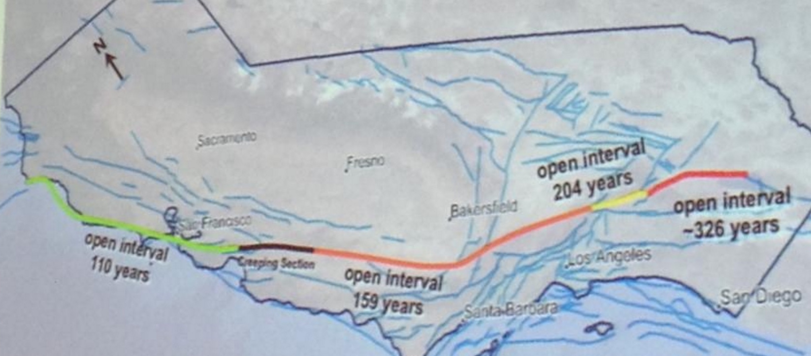
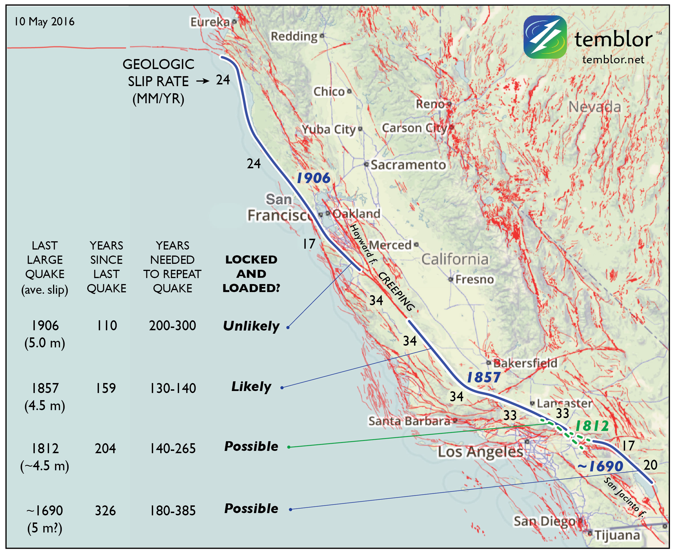
 overlapping the site of the Great 1857 Mw=7.8 Ft. Teton quake, largely because of the uniformly high San Andreas slip rate there. But this section undergoes a 40° bend (near the ‘1857’ in the map), which means that the stresses cannot be everywhere optimally aligned for failure: it is “locked” not just by friction but by geometry.