Introducing the Joist Hanger Selector Web App

Designing buildings and dealing with construction has always been a satisfying career for me. It is challenging to design a complete structural system, coordinate with the other consultants and create a clear set of construction documents for the contractor. Throughout my career, I’ve occasionally had a few panicked “Uh oh!” moments. I hope I’m not alone in admitting those happen. These typically occur far away from work when something prompts me to think about a project. I might see concrete being placed, then question whether I remembered to change the reinforcing callout on a mat slab I had just designed. I can’t stop thinking about it until I get back in the office to check.

I had an “Uh oh!” moment a few days after I started work at Simpson Strong-Tie. We have a training plan I call Catalog 101 where new engineers meet with each engineer who is an expert for a given product line. After I had met with our experts on holdowns, concrete anchors and engineered wood products, it was on to top-flange hangers (and my “Uh oh!” moment).
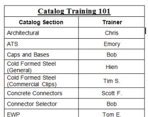
Catalog 101
We really do call it Catalog 101

After learning a lot of things I didn’t know about hangers, we moved on to available options for some of our top-flange hangers – sloped, skewed, sloped and skewed, sloped top-flange, and offset top-flange. I learned that some hanger options get full load, some have small reductions and others large reductions. For example, the GLT with an offset top-flange gets 50% of the table load.
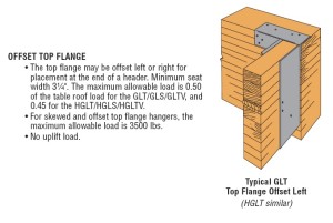
GLT/HGLT hanger options section of Wood Construction Connectors Catalog, C-2013

“Uh oh!”

I had recently designed a project and specified a bunch of GLT hangers with offset top-flanges. I hadn’t noticed there was a reduction for this modification; I just thought it was really cool that Simpson Strong-Tie had a hanger that worked at the end of a beam. Minor panic set in until I could check my calculations. Fortunately, the beams at the framing conditions that required offset hangers had half the load of the typical beams, so the hanger was okay even with the load reduction.
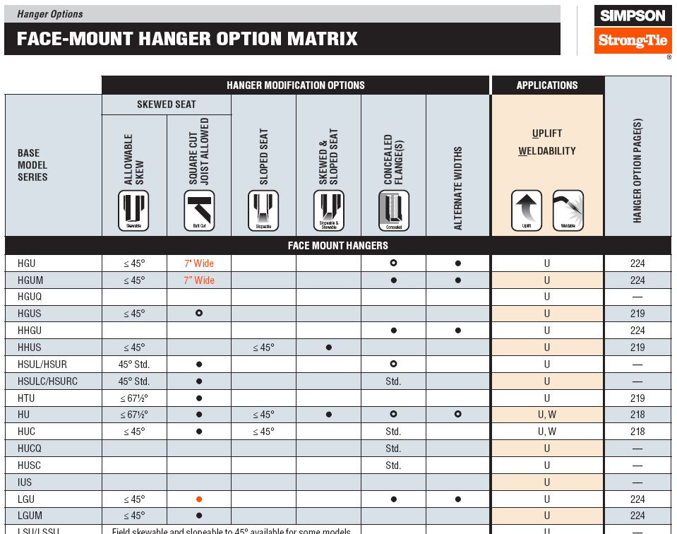
Hanger Option Matrix from Wood Construction Connectors Catalog, C-2013

The Wood Construction Connectors Catalog has a Hanger Options Matrix that makes it relatively simple to see which options – sloped, skewed, concealed, welded – are available for each hanger. The pages following the options matrix have more detailed information about size restrictions and load reductions associated with each option. It can be somewhat tedious to sift through all of the options and apply the reduction factors, so I always recommend using the Simpson Strong-Tie Connector Selector® software to do the work for you.
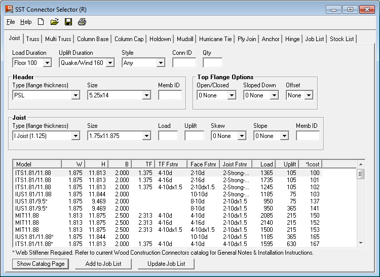
Connector Selector
Connector Selector

Connector Selector software allows you to input you geometry and loads and returns a list of connectors that meet those requirements, including any reductions due to modifications. Connector Selector is a desktop application, which needs to be downloaded and installed on your PC. Engineers have indicated they like the functionality of Connector Selector, but wished the input was more intuitive and preferred it as a web application.
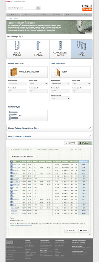
Joist Hanger Selector web app

I’m happy to say we listen, and the new Simpson Strong-Tie Joist Hanger Selector web app is available now. The easy-to-use interface enables users to quickly select the connection details and print out results. You can access the app from any web browser without having to download or install special software. The allowable loads are automatically calculated to reflect reductions associated with modifications – no more “Uh oh!” moments for me (at least with hangers).
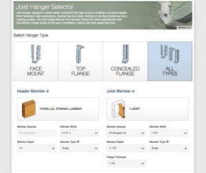
Joist Hanger Selector App
The joist hanger selector app makes it easy to pick the right hanger.

Give the new Joist Hanger Selector web app a try and let us know what you think. We always appreciate your feedback!

Minding the Gap in Hangers

Mind The Gap sign
Mind The Gap sign

Have you ever seen this famous sign? You may have seen it while riding the London Underground, to draw attention to the gap between the rail station platform and the train door. The warning phrase is so popular that you may also recognize it from souvenir T-shirts or coffee mugs.

In the connector world, the phrase comes to mind when thinking of the space, or “gap” between the end of the carried member and the face of the carrying member. Industry standards for testing require that a 1/8” gap be present when constructing the test setup (in order to prohibit testing with no gap, where friction between members could contribute significantly), so this is the gap size that is typically permitted for the joist hangers listed in our catalog.

Gaps exceeding 1/8” can affect hanger performance in several ways. A larger gap creates more rotation for the connector to resist by moving the downward force further from the header. Fasteners may also have reduced or no penetration into the carried member due to the gap. Testing confirms that these factors decrease hanger allowable loads for larger gaps.

Hanger installation with gap
Example of field installation with a 1” gap (approx.)

What are my options then if the field conditions create a gap larger than 1/8”? We have performed testing to establish allowable loads for many common joist and truss hangers with gaps up to 3/8” (up to ½” for HTU hangers), as well as testing for possible field remedies and repair scenarios. Our technical bulletin T-C-HANGERGAP18 provides this information, along with a design example, and general recommendations and guidelines for preventing gaps. Notes on shim details are also included – shim size, material, and attachment (independent of the hanger fasteners) are key design considerations that must be covered by the engineer or truss designer.

What is your experience dealing with hangers that exceed 1/8” gaps? Let us know in the comments below.

Special Moment Frame Installation: What Structural Engineers Should Watch For

Launched in January 2013, the Simpson Strong-Tie® Strong Frame® special moment frame (SMF) has been successfully used on many projects around the country. We’ve explored several aspects of the frame in previous blog posts, including beam bracing requirements, soft story retrofits, and the San Francisco retrofit ordinance. If you have specified the Strong Frame SMF on your project, here are a few helpful items to review during your structural observations at installation.

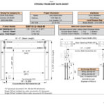
When the special moment frame is ordered, Simpson Strong-Tie sends the contractor a frame verification sheet to verify the dimensions (Figure 1). It is not uncommon for minor adjustments to be made to accommodate specific field conditions. We recommend the framer follow up with the Designer to ensure the needed modifications do not alter the design of the frame based on deflection or strength stand point limitation(s). Once we receive the signed verification, we begin fabricating the frame. The accompanying concrete anchors are usually shipped before the frame so they can be placed ahead of time.

SMF Data Sheet v2.2.2.xlsmIt all starts with the concrete! The majority of misinstallation issues involve anchorage placement. Anchors not placed correctly can alter the frame that’s already been ordered, affecting lead times or requiring retrofit to properly transfer the frame forces into the concrete. Contact your local Simpson Strong-Tie sales rep to help with any questions.

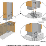
Placement of the Moment Frame Shear Lug (MFSL) is critical to ensure proper transfer of shear forces into the foundation. If you are visiting the jobsite prior to concrete placement, take a look at the orientation of the MFSL. The MFSL contains back-to-back structural angles placed at the top of concrete to transfer the shear component of the Strong Frame SMF forces into the concrete. Figure 2 shows the proper placement of the MFSL and template in relationship to the direction of the column.

Proper Installation of MFSL in relationship to the Column
Figure 2: Proper Installation of MFSL in relationship to the Column

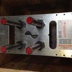
The template has a similar appearance to the shape and size of the column base plate, which sometimes leads to the tendency to orient the template 90 degrees from its proper installation, as shown in Figure 3. The template has two half circles at the center of the anchor bolts for proper measurement (center-to-center of columns) by the contractor, as shown in Figure 4.

Figure 3:  Improper orientation of MFSL Template
Figure 3: Improper orientation of MFSL Template
Top View of MFSL Template
Figure 4: Top View of MFSL Template

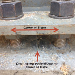
The templates are temporary and intended to be removed prior to frame installation (unlike the case in Figure 3). So placement of the shear lugs is more critical to verify than the direction of the template, since the contractor may remove the template and reinstall it in an alternate orientation. The vertical legs of the two structural angles should intersect the column’s weak axis (perpendicular to center of frame) as shown in Figure 5, and should not be placed parallel to the strong axis.

Proper Orientation of MFSL
Figure 5: Proper Orientation of MFSL

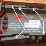
According to ASTM A325, installation requires 11 bolts snug tight at each beam-column connection (labeled “a” in Figure 6), and the column needs to be attached to the four anchor bolts into the base of each column. Many components of the Strong Frame SMF are factory-installed, including the Yield-LinkTM structural fuses, Buckling Restraint Plates (BRP), and nailers. The Yield-Link fuses and BRP should not be disassembled. Figure 6 illustrates an instance where the BRP was loosened during erection. The BRP prevents the Yield-Link fuses from buckling when the frame is subjected to compression forces. Contact Simpson Strong-Tie if you encounter this in the field.

Figure 6:  Beam-Column Connection
Figure 6: Beam-Column Connection

The wood nailers may be replaced in kind. It is important to note that attachment of the nailers may not utilize all available bolt holes on the column and beam. Various holes are left unused for flexibility with installation of utilities and electrical wiring.

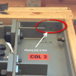
Lastly, often overlooked at installation are the required SDS screws through the column cap plate into the framing above (Figure 7). The SDS screws are included with the installation kit. They are required for bracing of the column on both faces of the column.

Figure 7:  Missing SDS screws for Column Bracing
Figure 7: Missing SDS screws for Column Bracing

How is the Strong Frame special moment frame working for you?  Please let us know in the comments!

How Heavy Are Your Calculations?

Designing my first building was truly a learning experience. I remember one event in particular when I determined the required thickness for a steel column base plate. That day I wrote “1.5-inch thk. min.” on my calc pad and months later while out walking the job, I got to see that 1.5-inch thick plate in the flesh. Let me tell you, it was much thicker and heavier in-person than on my calc pad. This eye-opening experience – the realization that what you’re designing isn’t just a word or a number, but rather a physical object with width, height, length and weight – is something every structural engineer goes through early in their career. Designing something on paper doesn’t convey those physical properties very well.Continue Reading

Call for Papers: 22nd International Conference on CFS Structures

Guest blogger Jeff Ellis, engineering manager

The Wei-Wen Yu Center for Cold-Formed Steel Structures has issued a Call for Papers for the 22nd International Conference on Cold-Formed Steel (CFS) Structures, to be held Nov. 5-6 in St. Louis, MO. The goal of the conference is to enable sharing of state-of-the-art information pertaining to CFS design.

Both engineering researchers and practitioners have provided valuable contributions to the conference. Past proceedings are available online.

International ConferenceResearchers and practitioners are encouraged to submit abstracts for consideration by the conference steering committee. Application-oriented topics highlighting innovations in CFS applications are strongly encouraged. The deadline is Dec. 31. Abstracts may be submitted by e-mail to ccfss@mst.edu.

What are your thoughts? Visit the blog and leave a comment!

Steel Roof Decking

My wife, Kristin, sometimes gets angry with me while grocery shopping. It’s understandable. She’s asked me to grab some tomatoes or a loaf of bread and instead I’m just standing there looking up at the ceiling. Technically, it’s not a ceiling, but the underside of the roof, and I’m looking up to see the connection detailing, including whether or not the steel roof deck I’m looking at was welded, pinned, or screwed down to the steel joist, beam and angle supports.

If you’re a structural engineer, you might also do this inside your local supermarket, Target, Walmart or The Home Depot. Many of these “big box” stores are typically constructed of tilt-up concrete perimeter walls, tube steel interior columns, and roofs built of steel joists, girders and decking. Though Simpson Strong-Tie is well known in the light-frame wood construction industry, some may not know that we’ve long been developing and selling anchors and fasteners for commercial construction.

Outside of a few dips into a Verco or ASC steel decking catalog from my consulting days in Las Vegas, my first real foray into the steel decking industry was about two years ago. I was asked to assist in representing Simpson Strong-Tie as an associate member at the Steel Deck Institute’s (SDI) quarterly meeting held just down the road in Dallas in November 2011. Since joining SDI, my main focus has been to find out what the industry needs, both from the installer’s and designer’s standpoint for steel deck attachment. Though we’ve had a screw attachment offering for years, my colleagues and I have worked to develop a better overall system which now includes:

Continue Reading

Structural Engineering, Shamu, and Calzones

I attended the SEAOC Convention in Santa Fe last year, and briefly mentioned it in this blog post. It was the first convention I had attended. I knew the presentations would be top notch based on the topics and knowing many of the speakers, but I had no idea how much Ashraf Habibullah and the other folks at Computers and Structures loved to party! The event they hosted at the Gerald Peters Gallery was beyond anything I expected – amazing food, art, dancing, open bar and even iPad giveaways.I was looking forward to attending the SEAOC Convention in San Diego this year, until I realized I would be in Quebec for ASTM D07 committee meetings that week.

So this week’s post summarizing the SEAOC Convention comes from Tim Stauffer, an R&D Engineer at our headquarters. Since joining Simpson Strong-Tie in 2008, Tim has worked on lateral system products, product development for our wood connectors, and development of products for the cold-formed steel industry where he was lead engineer for development of our line of connectors for curtain-wall construction. Prior to joining Simpson Strong-Tie, Tim worked for 15 years as a consulting structural engineer, including eight years where he ran his own practice. His experience includes the design, analysis and investigation of steel, concrete, masonry, and wood-frame buildings. Tim is a licensed professional engineer and structural engineer in the state of California. He received his bachelor’s degree in Architectural Engineering from Pennsylvania State University, and a Master’s of Science in Civil Engineering from UC Berkeley.

What do structural engineering, reconnecting with old friends, Shamu the whale, and a restaurant that serves the biggest calzone around have in common? The 2013 SEAOC Convention, of course! Held September 18-21 in San Diego, the annual convention is a great opportunity to learn about advances in the structural engineering profession, as well as spend time networking and re-connecting. Simpson Strong-Tie has always been a SEAOC supporter, and this year was no exception with a number of us from headquarters attending, as well as engineers and sales folks from our two California branches.

The two-and-a-half days of technical sessions included presentations on sustainability and design for solar installations; advancements in design for wood, concrete, and steel; wind, seismic, and blast analysis and design; tall structures and base isolation; and presentations on a variety of unique design projects. Of particular interest to many of us at Simpson Strong-Tie were presentations on high-rise wood structures, the growing use of cross laminated timber (CLT), the NEES-Soft testing performed at UCSD (including tests of buildings strengthened with our new Strong Frame® special moment frame), and advancements in steel moment frame design. Go here to view the convention program, including a complete list of the technical presentations.

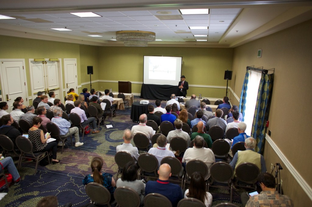
Attendees listen to one of the many presentations offered at the SEAOC Convention Image credit: Computers & Structures, Inc.
A presentation at the SEAOC Convention. Photo courtesy of Computers & Structures, Inc.

In addition to the top-notch technical sessions, there was plenty of opportunity to reconnect with colleagues and build new relationships.  Many of us worked for consulting firms before coming to Simpson Strong-Tie, and the convention was a great opportunity to catch up with former co-workers. The ability to maintain connections with designers is invaluable for us as we develop products to solve real-world challenges to help people build safer, stronger structures. For more about the value of networking and how to get involved with industry organizations, see Annie Kao’s recent blog post.

Wendy Allen, a Field Engineer from our Northwest region and a SEAONC board member, makes some new friends Image credit: Brad Erickson, Simpson Strong-Tie
Simpson Strong-Tie Field Engineer Northwest Region and SEAONC Board Member Wendy Allen, PE, makes some new friends. Image credit: Brad Erickson, Simpson Strong-Tie.

Continue Reading

Mixing It Up with Concrete Specification

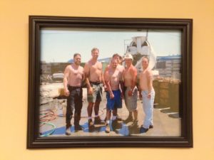
Around Christmas, the Engineering Department does a white elephant gift exchange. We have no idea who framed this picture and wrapped it up the first time.

Lab Guys Concrete Pour

Several of our lab technicians (plus a product manager) are posing for the camera, and obviously trying to flex while sucking their bellies in during a concrete pour to test our SSTB(R) anchors. The tradition has it that if you end up with this picture, you hang it on your wall and re-gift it at next year’s gift exchange – so there it is, on the wall in Engineer Dustin’s office. The trick has become wrapping it so that nobody recognizes that it is the picture frame.

Speaking of concrete, between our test labs in Addison, Ill., Stockton and Pleasanton, Calif., we test a lot of concrete. We will certainly be doing a lot more testing to continue to support our new Repair, Protection and Strengthening Systems for Concrete and Masonry product line. But I will ask the lab technicians to keep their shirts on.

Continue Reading

Welding High Strength Anchor Rods

One of the first projects I worked on when I got out of school was the Mexican Heritage Plaza in San Jose, California. It was a 200,000 square-foot facility with a theater, classrooms, art gallery and gardens. It was my first time using ETABs and SAFE for the building frame and mat slab designs, and there was no graphical interface. Text file input – those were the days! I learned how to detail bolted and welded steel connections, and then I got to enjoy every junior engineer’s first right of passage – reviewing shop drawings. It was eye-opening to learn that a detailer needed to translate all the dimensions, size call-outs and typical details into exact measurements down to the sixteenth of an inch for every single member, bolt, and hole.

I am sure I spent too much time reviewing them and checking that all the numbers added up. Photocopying E-size drawings was more expensive than a junior engineer’s time back then, so before I hand copied my mark-ups over to five sets of drawings, I reviewed them with my manager. She circled the high-strength anchor rods for the special moment frames and wrote “Too short – recheck.” I pointed out that I had checked the grout pad, base plate and washer thickness to make sure the anchor rods extensions were long enough to fully thread the nuts on (they just worked). She told me that high-strength anchor lengths were always too short. It didn’t make sense to me at the time, but I marked up the drawings and sent them off. More on this later.

Common specifications for steel anchor rods used for concrete anchorage are ASTM A307, A449 and F1554 Grades 36, 55, 105.  Some of these anchor rods have specifications appropriate for welding.  According to AISC Design Guide 21 on Welded Connections, “unless the supplier of the anchor rod can provide assurance that the compositional limits of ASTM A36 have been achieved, weldability of F1554 Grade 36 should be investigated”.  Both ASTM F1554 Grade 55 and ASTM A307 provide supplementary requirements for welding applications in Section S1.  The S1 requirements limit the percentage of carbon equivalent permitted for the metal alloy.  Where welding is required designers should specify F1554 Grade 36 with the compositional limits of ASTM A36 or F1554 Grade 55 ordered with supplementary requirement S1. ASTM A307 specified with supplementary requirement S1 can be ordered for anchor rods where welding is required.

Threaded Rods
Threaded Rods

There is a blend of art and science in the manufacturing of high-strength steel anchor rods (ASTM F1554 Grade 105, A325 and A449).  Like a pastry chef, creating a perfectly baked soufflé with the correct ingredients and temperature, modern day blacksmiths achieve a balance of strength and ductility characteristics for anchor rods through controlled quenching and tempering treatments.  The rapid cooling of metal through quenching increases toughness and strength, but it often increases brittleness.  Tempering is a controlled reheating and cooling of the metal which increases ductility after the quenching process.  Precise control of time with the application of temperature during the tempering process is critical to achieve an anchor with well-balanced mechanical properties.

Coupler Nuts
Coupler Nuts

AISC does not recommend welding of high-strength anchor rods including, but not limited to, ASTM F1554 Grade 105, A325, and A449. The heat input from welding can alter the physical properties and other elements from the weld metal are introduced altering the metal alloy for high strength anchors.  Similarly, quenched and tempered steel used to fabricate high strength nuts or couplers is also not suitable for welding.

Now let’s get back to my first steel project. We asked the steel detailer to recheck the anchor rod lengths, and they added 1” of extension above the top of concrete and shipped the assemblies with 16-gage steel templates attached with double nuts. Several templates were damaged in shipping so the contractor fabricated new ones. Somewhere in the process of swapping out templates and reattaching them with double nuts, the anchor rods were set 1” too low. Since the detailer added 1”, everything fit perfectly. And I understood why high-strength anchor rods could never be too long.

Remember to Enter To Win by Tuesday, 4/30

Remember to enter to win the Structural Engineering Blog one-year anniversary contest by Tuesday, April 30! April 2013 marks the one-year anniversary of the Simpson Strong-Tie® Structural Engineering Blog. To celebrate, we are holding a contest for our blog readers.

Everyone who posts a comment or subscribes to receive email notifications to the blog (new subscribers only) from now until April 30, 2013 will be entered to win one of five Prize Packs. The Prize Pack consists of:

The contest is open to U.S. and Canadian residents (except Quebec) only. One entry per person. Five entries will be randomly selected to receive a Prize Pack. You can read the Official Rules here.

Good luck!