Understanding and Meeting the ACI 318 – 11 App. D Ductility Requirements – A Design Example

If you’re one of the many engineers still confused by the ACI 318 – 11 Appendix D design provisions, this blog will help explain what’s required to achieve a ductile performing anchorage. Most building codes currently reference ACI 318 – 11 Appendix D as the required provision for designing a wide variety of anchor types that include expansion, undercut, adhesive and cast-in-place anchors in concrete base materials. This blog post will focus on section D.3.3.4.3(a) for an anchor located in a high seismic region. We’ll go over what these requirements are with a simple design example.

Ductility is a benefit in seismic design. A ductile anchor system is one that exhibits a meaningful degree of deformation before failure occurs. However, ductility is distinct from an equally important dimension called strength. Add strength, and a ductile steel element like the one shown in Figure 1 can now exhibit toughness. During a serious earthquake, a structural system with appreciable toughness (i.e., one that possesses both strength and ductility in sufficient degree) can be expected to absorb a tremendous amount of energy as the material plastically deforms and increases the likelihood that an outright failure won’t occur. Any visible deformations could help determine if repair is necessary.

Figure 1 – ½" mild steel threaded rod tensilely loaded to failure (starting stretch length = 8d)
Figure 1 – ½” mild steel threaded rod tensilely loaded to failure (starting stretch length = 8d)

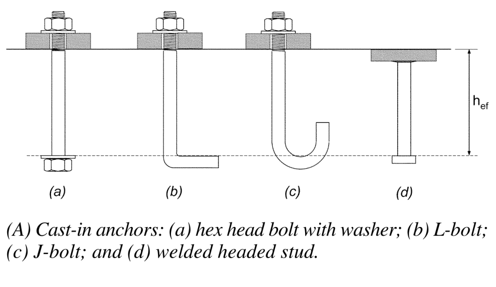
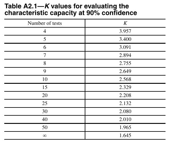
Let’s start off with a simple example that will cover the essential requirements for achieving ductility and applies to any type of structural anchor used in concrete. We’ll arbitrarily choose a post-installed adhesive anchor. This type of anchor is very common in concrete construction and is used for making structural and nonstructural connections that include anchorage of sill plates and holdowns for shear walls, equipment, racks, architectural/mechanical/electrical components and, very frequently, rebar dowels for making section enlargements. We’ll assume the anchor is limited to resisting earthquake loading in tension only and is in seismic design category C – F. Section D.3.3.4.2 requires that if the strength-level earthquake force exceeds 20% of the total factored load, that the anchor be designed in accordance with section D.3.3.4.3 and D.3.3.4.4. We will focus on achieving the ductility option, (a), of D.3.3.4.3.

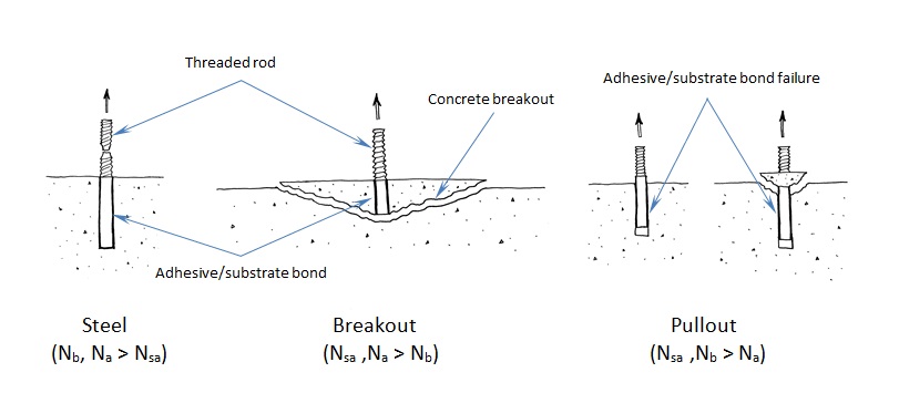
To understand anchor ductility we need to first identify the possible failure modes of an anchor. Figure 2 shows the three types of failure modes we can expect for an adhesive anchor located away from a free edge. These three failure modes generically apply to virtually any type of anchor (expansion, screw, cast-in-place or undercut). Breakout (Nb) and pullout (Na) are not considered ductile failure modes. Breakout failure (Nb) can occur very suddenly and behaves mostly linear elastic and consequently absorbs a relatively small amount of energy. After pullout failure (Na) has been initiated, the load/displacement behavior of the anchor can be unpredictable, and furthermore, no reliable mechanism exists for plastic deformation to take place. So we’re left with steel (Nsa). To achieve ductility, not only does the steel need to be made of a ductile material but the steel must govern out of the three failure modes. Additionally, the anchor system must be designed so that steel failure governs by a comfortable margin. Breakout and pullout can never control while the steel yields and plastically deforms. This is what is meant by meeting the ductility requirements of Appendix D.

Figure 2 –Three possible failure modes for an adhesive anchor loaded in tension
Figure 2 – Three possible failure modes for an adhesive anchor loaded in tension

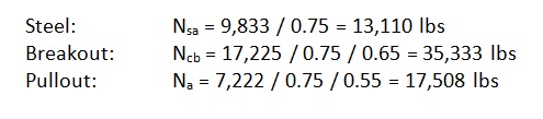
Getting back to our design example, we have a single post-installed 5/8” diameter ASTM F1554 Gr. 36 threaded rod that’s embedded 12” deep, in a dry hole, in a concrete element that has a compressive strength of 2,500 psi. The concrete is 18” thick and we assume that the edge distance is large enough to be irrelevant. For this size anchor, the published characteristic bond strength is 743 psi. Anchor software calculations will produce the following information:

ductility4

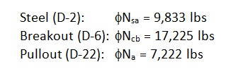
The governing design strength is compared to a demand or load combination that’s defined elsewhere in the code.

Here’s the question: Before proceeding with the remainder of this blog, judging by the design strength values shown above, should we consider this anchorage ductile? Your intuition might tell you that it’s not ductile. Why? Pullout clearly governs (i.e., steel does not). So it might come as a surprise to learn that this adhesive anchor actually is ductile!

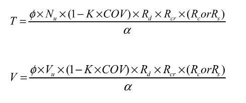
To understand why, we need to look at the nominal strength (not the design strength) of the different anchor failure modes. But first let’s examine the equations used to determine the design strength values above:

ductility5

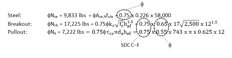
The above values incorporate the notation φ (“phi”) and a mandatory 0.75 reduction factor for nonductile failure modes (Ncb ,Na) for applications located in high seismic areas (seismic design category C–F). The φ factor is defined in section D.4. However, manufacturers will list factors specific to their adhesive based on anchor testing. The mandatory 0.75 reduction comes from section D.3.3.4.4 and is meant to account for any reduction associated with concrete damage during earthquake loading. The important thing to remember is that the nominal strength provides a better representation of the relative capacity of the different failure modes. Remove these reduction factors and we get the following:

ductility6

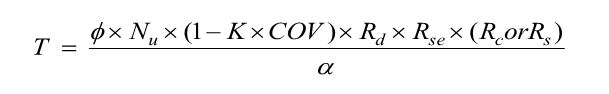
Now steel governs since it has the lowest strength. But we’re not done yet. Section D.3.3.4.3.(a).1 of Appendix D requires that the expected steel strength be used in design when checking for ductility. This is done by increasing the specified steel strength by 20%. This is to account for the fact that F1554 Gr. 36 threaded rod, for example, will probably have an ultimate tensile strength greater than the specified 58,000 psi. (Interestingly, the ultimate strength of the ½” threaded rod tested in Figure 1 is roughly 74 ksi, which is about 27% greater than 58,000 psi.) With this in mind, the next step would be to additionally meet section D.3.3.4.3.(a).2 such that the following is met:

ductility7

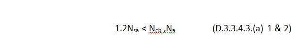
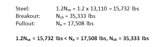
By increasing the steel strength by 20%, the nominal strength of the nonductile failure modes (Ncb ,Na) must be at least that much greater to help ensure that a ductile anchor system can be achieved. The values to compare finally become:


ductility8
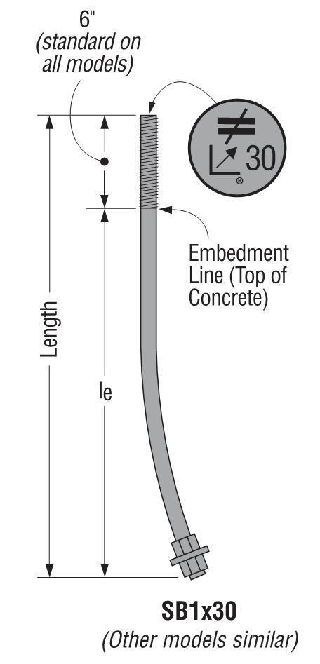
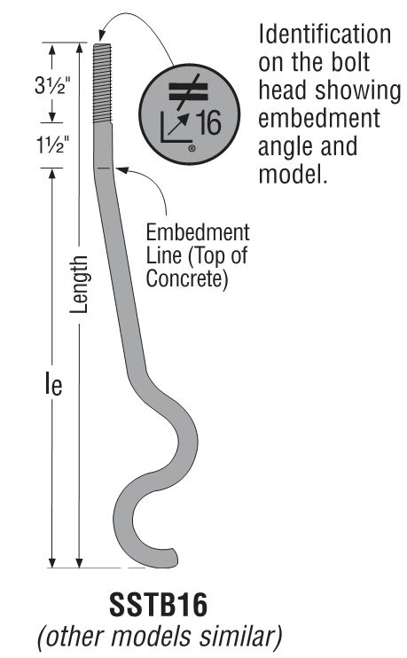
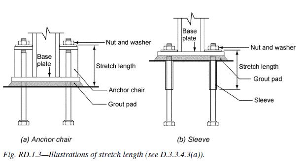
Now steel governs, but one more thing is required. As shown in Figure 3, Section D.3.3.4.3.(a).3 of Appendix D also requires that the rod be made of ductile steel and have a stretch length of at least eight times the insert diameter (8d). Appendix D defines a ductile steel element as exhibiting an elongation of at least 14% and a reduction in area of at least 30%. ASTM F1554 meets this requirement for all three grades of steel (Grade 36, 55 and 105) with the exception of Grade 55 for anchor nominal sizes greater than 2”. Research has shown that a sufficient stretch length helps ensure that an anchor can experience significant yielding and plastic deformation during tensile loading. The threaded rod shown in Figure 1 was tested using a stretch length of 4” (8d). Lastly, section D.3.3.4.3.(a).4 requires that the anchor be engineered to protect against buckling.

Figure 3 – Stretch length

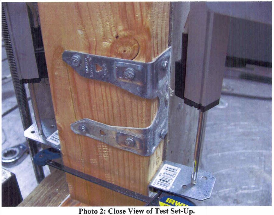
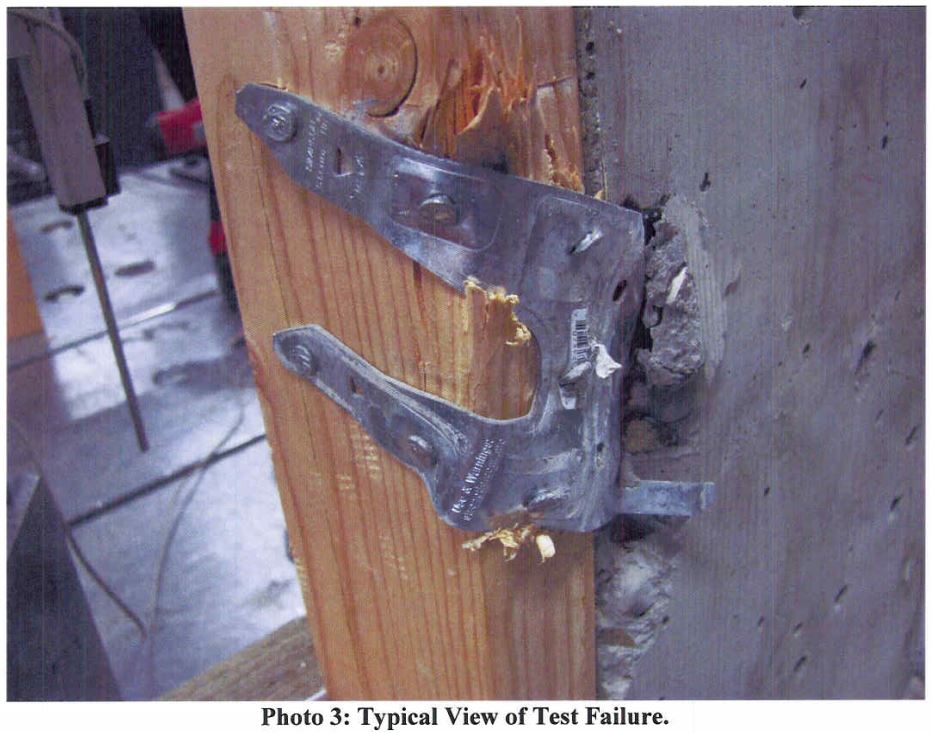
Appendix D doesn’t require that an anchor system behave ductilely. Three additional options exist for Designers in section D3.3.4.3. Option (b) allows for the design of an alternate failure mechanism that behaves ductilely. Designing a base plate (or support) that plastically hinges to exhibit ductile performance is one example. Option (c) involves a case where there’s a limit to how much load can be delivered to the anchor. Although option (c) under D.3.3.4.3 falls under the tensile loading section of Appendix D, the best example would apply to anchorage used to secure a wood sill plate or cold-formed steel track. We know from experiments that the wood crushes or the steel yields and locally buckles at a force less than the capacity of the concrete anchorage. Clearly energy is absorbed in the process. The most commonly used option is (d), which amplifies the earthquake load by Ωo. Ωo can be found in ASCE 7 – 10 for both structural and nonstructural components. The value of Ωo is typically taken to be equal to 2.5 (2.0 for storage racks) and is intended to make the anchor system behave linear elastically for the expected design-level earthquake demand.

These same options exist for shear loading cases. However, achieving system ductility through anchor steel is no longer an option for shear loading according to ACI 318 – 11, because the material probably won’t deform appreciably enough to be considered ductile.

While factors such as edge-distance and embedment-depth restrictions make achieving ductility difficult for post-installed anchors, it should come as some consolation that in many cases the Designer can achieve ductile performance for cast-in-place anchors loaded in tension through creative detailing of reinforcing steel (section D.5.2.9) to eliminate breakout as a possible failure mode. This has been explored in some detail in two previous Simpson Strong-Tie blogs titled “Anchor Reinforcement for Concrete Podium Slabs” and “Steel Strong Wall Footings Just Got a Little Slimmer.”


What Factors Contribute To A “Resilient” Community?

The world has seen many increasingly catastrophic natural disasters in the past decade, including Hurricane Katrina (Category 3) striking New Orleans in 2005, 2010’s 7.0 magnitude Haiti and 8.8 magnitude Chili earthquakes, the 9.0 magnitude Japan earthquake along with the Christchurch earthquake (6.3 magnitude) in 2011, the tornado outbreak in 2011 which included an EF4 striking Tuscaloosa, AL and a multiple-vortex EF5 striking Joplin, MO. We also saw Category 2 Hurricane Sandy, the largest Atlantic hurricane on record in 2012 and the EF5 tornado striking Moore, Oklahoma in 2013.

Continue Reading

Anchor Testing for Light-Frame Construction

I started off doing a four-part series on how connectors, fasteners, concrete anchors and cold-formed steel products are tested and load rated. I realized that holdown testing and evaluation is quite a bit different than wood connector testing, so there was an additional post on holdowns. We have done several posts on concrete anchor testing (here and here), but I realize I never did a proper post about how we test and load rate concrete products per ICC-ES AC398 and AC399.

AC398 – Cast-in-place Cold-formed Steel Connectors in Concrete for Light-frame Construction and AC399 – Cast-in-place Proprietary Bolts in concrete for Light-frame Construction are two acceptance criteria related to cast-in-place concrete products.

Cold-formed steel connectors embedded in concrete are not considered in ACI 318 Appendix D, so it was necessary to create criteria for evaluating those types of connectors. Some examples of products covered by AC398 are the MASA mudsill anchor, CBSQ post base, and the STHD holdown.

MASA mudsill anchor
MASA mudsill anchor
CBSQ post base
CBSQ post base
STHD holdown
STHD holdown

ACI 318 Appendix D addresses the design of cast-in-place anchors. However, the design methodology is limited to several standard bolt types.

ACI 318 Appendix D Cast-in anchors

There are a number of anchor bolt products that have proprietary features that fall outside the scope of ACI 318, so AC399 fills in that gap by establishing test procedures to evaluate cast-in-place specialty anchors. Simpson Strong-Tie SB and SSTB anchor bolts are two families of anchors we have tested in accordance with AC399.

SB Anchor Bolt
SB Anchor Bolt
SSTB Anchor Bolt
SSTB Anchor Bolt

SB and SSTB anchors have a sweep geometry which increases the concrete cover at the anchored end of the bolt, allowing them to achieve higher loads with a 1¾” edge distance. The SSTB is anchored with a double bend, whereas the SB utilizes a plate washer and double nut.

AC398 (concrete connectors) and AC399 (proprietary bolts) are similar in their test and evaluation methodology. AC398 addressing both tension and shear loads, whereas AC399 is limited to tension loads. Testing requires a minimum of 5 test specimens. These are the allowable load equations for AC398 and AC399:

AC398 - Allowable Load Equation
AC398 – Allowable Load Equation
AC399 - Allowable Load Equation
AC399 – Allowable Load Equation

For comparison, here is the standard AC13 allowable load equation for joist hangers:

Allowable Load = Lowest Ultimate / 3

Without getting into Greek letter overload, what are these terms doing?

Nu (or Vu) is the average maximum tested load. Calculating averages is something I actually remember from statistics class. Everything else I have to look up when we do these calculations.

(1 – K x COV) uses K as a statistical one-sided tolerance factor used to establish the 5 percent fractile value with 90% confidence. This term is to ensure that 95% of the actual tested strengths will exceed the 5% fractile value with 90% confidence. COV is the coefficient of variation, which is a measure of how variable your test results are. For the same average ultimate load, a higher COV will result in a lower allowable load.

The K value is 3.4 for the minimum required 5 tests, and it reduces as you run more tests. As K decreases, the allowable load increases. In practice, we usually run 7 to 10 tests for each installation we are evaluating.

Table A2.1 – K values for evaluating the characteristic capacity at 90% confidence

Rd is seismic reduction factor, 1.0 for seismic design category A or B, and 0.75 for all others. This is similar to what you would do in an Appendix D anchor calculation, where anchor capacities in higher seismic regions are reduced by 0.75.

Rs and Rc are reduction factors to account for the tested steel or concrete strength being higher than specified. There are some differences in how the two acceptance criteria apply these factors, which aren’t critical to this discussion. Φ is a strength reduction factor, which varies by failure mode and construction details. Brittle steel failure, ductile steel failure, concrete failure and the presence of supplemental reinforcement.

The α factor is used to convert LRFD values to ASD values. So α = 1.0 for LRFD and α = 1.4 for seismic and 1.6 for wind. Both criteria also allow you to calculate alpha based on a weighted average of your controlling load combinations. This has never made a lot of sense to me in practice. If you are going to work through the LRFD equations to get a different alpha value, you might as well do LRFD design.

MASA - Test Setup MASA - Test Failure

Rse is a reduction factor for cyclic loading, which is applied to proprietary anchor bolts covered under AC399, such as the SSTB or SB anchors. A comparison of static load and cyclic load is required for qualification in Seismic Design Category C through F. Unlike the cracked reduction factor, manufacturers cannot take a default reduction if they want recognition for high seismic.

Due to the differences in AC398 and AC399 products, the load tables are a little different. AC398 products end up with 4 different loads – wind cracked, wind uncracked, seismic cracked and seismic uncracked.

CBSQ Load Table
CBSQ Load Table

AC399 products are a little simpler, having just wind and seismic values to deal with.

SSTB Load Table
SSTB Load Table

What are your thoughts? Let us know in the comments below.

Resilience by Design: City of Los Angeles Lays Out a Seismic Safety Plan

“From a seismological standpoint, Northridge was not a big earthquake.” This is first sentence of the “Resilience by Design” report by L.A. Mayor’s Seismic Safety Task Force led by Dr. Lucy Jones of the U.S. Geological Survey (USGS). The report is the culmination of a year-long investigation into the greatest vulnerabilities of the city from a major seismological event. Continue Reading

Seismic Safety Regulations and Solutions

I have a special place in my heart for old buildings. Every college design course I took was related to new design. Concrete, steel, or wood design, the design problem was invariably part of a new building. I thought structural engineers designed new buildings. When I showed up for my first day of work wearing dress pants, a button-down shirt and a tie, I was handed a flashlight, tape measure, a clipboard and a Thomas Guide map (no Google maps back then) and sent to do as-built drawings for a concrete tilt-up that we were retrofitting.

When I was designing buildings, I created a lot of as-built drawings. Figuring out how a building was put together, what the structural system was (or wasn’t!) and designing a lateral load path in these old, and often historic buildings, was immensely satisfying. Knowing that history, it should not be surprising I have done a number of blog posts related to seismic retrofits. Soft-Story Retrofits, San Francisco’s Soft-Story Retrofit Ordinance, Remembering Loma Prieta, Resilient Communities, FEMA P-807, and Home Seismic Retrofit (there are probably a couple I forgot).

This week, Los Angeles Mayor Eric Garcetti proposed new seismic safety regulations . The recommendations are to retrofit soft-story wood-framed buildings within five years and older concrete buildings within 30 years. While these are only recommendations, it is encouraging to see politicians supporting policies to promote resiliency and life safety.

In San Francisco, thousands of building owners are already required by law to seismically retrofit multi-unit (at least five) soft-story, wood-frame residential structures that have two or more stories over a “soft” or “weak” story. These buildings typically have parking or commercial space on the ground floor with two or more stories above. As a result, the first floor has far more open areas of the wall than it actually has sheathed areas, making it particularly vulnerable to collapse in an earthquake.

Photo credit: J.K. Nakata and the U.S. Geological Survey

San Francisco’s ordinance affects buildings permitted for construction before Jan. 1, 1978. Mandatory seismic retrofit program notices requiring that buildings be screened were sent out in September, 2013, to more than 6,000 property owners. It is anticipated that approximately 4,000 of those buildings will be required to be retrofitted by 2020.

“When we look at the demographic of these buildings, they house approximately 110,000 San Franciscans. It’s paramount that we have housing for people after a disaster. We know we will see issues in all types of buildings, but this is an opportunity for us to be able to retrofit these buildings while keeping an estimated 1100,000 San Franciscans in their homes and, by the way of retrofit, allowing them to shelter in place after a disaster,” according to Patrick Otellini, San Francisco’s chief resilience officer and director of the city’s Earthquake Safety Implementation Program. “This exponentially kick starts the city’s recovery process.”

One solution to strengthen such buildings is the Simpson Strong-Tie® Strong Frame® special moment frame. Its patented Yield-Link™ structural fuses are designed to bear the brunt of lateral forces during an earthquake, isolating damage within the frame and keeping the structural integrity of the beams and columns intact.

Simpson Strong-Tie® Strong Frame® special moment frame

“The structural fuses connect the beams to the columns. These fuses are designed to stretch and yield when the beam twists against the column, rather than the beam itself, and because of this the beams can be designed without bracing. This allows the Strong Frame to become a part of the wood building and perform in the way it’s supposed to,” said Steve Pryor, S.E., International Director of Building Systems at Simpson Strong-Tie. “It’s also the only commercially-available frame that bolts together and has the type of ductile capacity that can work inside of a wood-frame building.”

Installation of the Simpson Strong-Tie® Strong Frame® special moment frame

Another key advantage of the Simpson Strong-Tie special moment frame is no field welding is required, which eliminates the risk of fire in San Francisco’s older wood-framed buildings.

To learn more about San Francisco’s retrofit ordinance, watch a new video posted on strongtie.com/softstory. For more information about the Strong Frame special moment frame, visit strongtie.com/strongframe.

Wood Shear Wall Design Example

Two weeks ago, I had the chance to present to the Young Members Group of the Structural Engineering Association of Metro Washington on the topic of Multi-Story Light-Frame Shear Wall Design. With all of the large firms in the D.C. area, it wasn’t a big surprise to find out that only about one-third of the group had experience with light-frame shear wall design.

However, while researching civil/structural engineering programs in the Midwest and Northeast last week (for our Structural Engineering/Architecture Student Scholarship program), I was disappointed to find that only about a quarter of the top engineering programs offer a wood design course. So I thought it might be helpful to post a wood shear wall design example this week.

The example is fairly basic but includes an individual full-height and perforated shear wall analysis for the same condition. The design is based on wind loading and SPF framing, both common in the Midwest/Northeast, and is based on the provisions and terms listed in the 2008 Special Design Provisions for Wind and Seismic (SDPWS), available for free download here, along with the recently posted 2015 version.

Multi-Story Shear Wall Example: Wind Loads with SPF Framing

Given:SE blog 1

  • 2012 IBC & 2008 SDPWS
  • 3-Story Wood Framed Shear Wall Line
  • ASD Diaphragm Shear Forces from Wind as Shown
  • Wall and Opening Dimensions as Shown

Solution:

  1. Determine total shear force in each shear wall line.
  2. Determine the Induced Unit Shear Force, v, for use with both shear wall types and the Maximum Induced Unit Shear Force, vmax, for the perforated shear wall collectors, shear transfer, and uniform uplift. Note the following:
    1. vmax requires the determination of the Shear Capacity Adjustment Factor, CO, for the perforated shear wall.
    2. The SDPWS provides two methods for determining CO, a tabulated value or a calculated value. This example uses the more precise calculated value.
    3. The perforated method requires the collectors be designed for vmax and the bottom plate to be anchored for a uniform uplift equal to vmax (as illustrated in the following figure).

SE blog 2

SE blog 43. Determine the Tension, T, and Compression, C, forces in the chords (assume no contribution from dead load for this example). Note the following:

    1. Reverse wind loading will require a mirror image of the T & C forces shown in the following figure.
    2. The tension forces, T, shown in the example reflect the cumulative tension forces as they are transferred down from post-to-post, as is typical with traditional holdowns. For continuous rod systems like ATS, the incremental tension forces (resulting from the unit shear, vor vmax, at that level only) must also be determined as shown in the shear wall specification table at the end of this example.

SE blog 5

SE blog 5 SE blog 64. Determine sheathing material and fastening pattern based on v calculated in Step 2. The table below is based on 7/16″ wood structural panel sheathing values in SDPWS Table 4.3A.

SE blog 7

    1. Individual Full-Height Shear Wall:

i.     v3=227 plf: Use 7/16 OSB with a 6:12 nailing pattern which has an allowable load of 336 plf

ii.     v2=409 plf: Use 7/16 OSB with a 4:12 nailing pattern which has an allowable load of 490 plf

iii.     v1=591 plf: Use 7/16 OSB with a 3:12 nailing pattern which has an allowable load of 630 plf

B. Perforated Shear Wall (apply CO factor to allowable shear capacity):

i.     v3=227 plf: Use 7/16 OSB with a 6:12 nailing pattern which has an allowable load of 255 plf

ii.     v2=409 plf: Use 7/16 OSB with a 3:12 nailing pattern which has an allowable load of 479 plf

iii.     v1=591 plf: Use 7/16 OSB on both sides of the wall with a 4:12 nailing pattern which has an allowable load of 338*2=676 plf

5. Size the posts for compression. Simpson provides some useful tables in the back of the connector catalog with allowable tension and compression loads for a variety of sizes, heights, and species of posts.

6. Select holdowns for the tensions loads and verify post sizes are sufficient. For higher aspect ratio shear walls, the post size and holdown type may significantly reduce the moment arm between center of tension and center of compression, resulting in higher tension and compression forces.

The tables below show the shear wall specification for the walls in the example in a typical format. Note that they do not include some detailing that is required for items such as the uniform uplift force on the bottom plate of all perforated shear walls, or the perforated shear walls with OSB sheathing on both sides.

SE blog 8

There are different ways to address the loads, so let us know if you would do anything differently in your designs.

Remembering Barclay Simpson

On Saturday evening, Barclay Simpson passed away peacefully in his sleep, surrounded by his family. He was 93 years old. With Barc’s passing, Simpson Strong-Tie has lost a beloved and inspirational leader. Our country has lost a generous philanthropist, visionary and great American entrepreneur. Those of us who were fortunate enough to know and work with Barc have lost a dear friend, champion and guide.

Barc’s contributions to the construction industry, non-profit community and our employees are immeasurable. He instilled the core values — our “Secret Sauce” — that have made Simpson Strong-Tie a unique and inspiring place to work and have built our reputation as a quality, trusted manufacturer and solid corporate citizen.

Barclay Simpson

The first time I met Barc was less than a week after I started working in the R&D department. I was meeting with a product manager and Barc was walking by, so he stopped in to say hello. We introduced ourselves and chatted for a few minutes. I told him about my work experience, where I went to school, what I was working on, and he even asked where I grew up. He was genuinely interested in getting to know me, which made me feel welcome.

I later noticed that Barc usually parked at the end of the building furthest from his office. He would take a different path through the building – sometimes through engineering, other times he would walk through marketing, accounting, or even the connector test lab. Barc cared deeply for all of his employees, and the intentionally long walk gave him the opportunity to talk with folks.

He firmly believed that everybody in the company is important, and he took every opportunity to remind us. In the video, Barclay Simpson’s Nine Principles of Doing Business, Barc speaks quite passionately about dignifying the contribution of every individual at every level.

In the end of a previous blog post, I mentioned Barc’s 1974 list of Rambling Thoughts on Making One’s Fleeting Moment on This Planet a Pleasant One. In the context of that post, the thoughts of “Attitude Conquers All” and “Keep it light. It really isn’t that important” were appropriate.

Thinking of Barc and his legacy, I prefer this rambling thought from his list:

Strive to have a POSITIVE EFFECT upon those lives touched by your own.

The Importance of Resilient Communities During Earthquakes

Imagine that it’s 4:30 a.m. and suddenly you’re awakened by strong shaking in your home. Half asleep, you hang on to your bed hoping that the shaking will stop soon. All of a sudden, the floor gives away and you fall. You think, “What just happened? How could this have possibly occurred? Am I alive?”

These could have been the thoughts of Southern California residents living in one of the many apartment buildings, which collapsed on January 17, 1994, during a 6.7 magnitude earthquake. The Northridge Earthquake brought awareness to buildings in our communities with a structural weakness known as a soft story, a condition that exists where a lower level of a multi-story structure has 20% or less strength than the floor above it. This condition is prevalent in buildings with tuck-under parking and is found in multistory structures throughout San Francisco, Los Angeles and other cities (see Figure 1). These structures are highly susceptible to major damage or collapse during a large seismic event (see Figure 2).

Soft Story building
Figure 1: Multi-unit wood-frame building with first weak story.
Aftermath of an earthquake
Figure 2: Collapsed soft story tuck under parking building. Image courtesy of LA Times

Soft story retrofits help to strengthen our communities and make them more resilient to major disasters. There are several resources available to structural engineers that need to retrofit weak-story buildings. Some of these resources are mentioned in our September 18 blog post.

During the 2014 SEAOC Convention held in Indian Wells on September 10-13, speakers discussed different methods, analysis and research that address the behavior of various materials and construction types during seismic events along with approaches to retrofit historically poor performing structures. This information can be viewed from the convention’s proceedings available at www.seaoc.org.

On October 20, 2014, the Structural Engineers Association of Southern California (SEAOSC) will be hosting their 4th annual Strengthening Our Cities BAR Summit in downtown Los Angeles. This event brings together many different stakeholders in our built environment, including public officials, building owners and managers, business owners, insurance industry representatives, emergency managers and first responders, and design professionals.

Many prestigious thought leaders, including USGS Seismologist Dr. Lucy Jones will be speaking at the summit, discussing such topics as tools and analysis methods for retrofitting vulnerable buildings and the Building Occupancy Resumption Program (BORP).

Expect a great day full of useful information about ways to strengthen our communities and prepare for major earthquakes as well as opportunities to network with like-minded peers. For additional information and to register, visit www.barsummit.org. We also hope you’ll visit our booth. We look forward to speaking with you there.

Home Seismic Retrofit

The 6.0 magnitude earthquake that struck Napa, CA, in August caused more than 200 injuries and structural damage to many homes and businesses throughout the area. The quake was the largest to hit the San Francisco Bay Area since the Loma Prieta earthquake (6.9 magnitude) in 1989, prompting the governor to declare a state of emergency.

I have done several posts about San Francisco’s Soft-Story Retrofit Ordinance and some of NEES-Soft testing related to soft-story retrofits. The soft-story ordinance only addresses multi-unit residential units and does not require retrofit of single-family homes. Cities are reluctant to mandate seismic evaluation and retrofit of single-family homes for a number of reasons that I won’t discuss here. The draft Earthquake Safety Implementation Program (ESIP) for San Francisco will not recommend mandatory retrofit of single-family homes until 2030.

CAPSS Implementation Priority Worksheet

The good news is homeowners can retrofit their homes without waiting for the government. A couple years ago in this post, I discussed some of the tools available to retrofit existing buildings.

One of these tools is the 2012 International Existing Building Code (IEBC). The IEBC has provisions for repair, alteration, addition or change of occupancy in existing buildings and for strengthening existing buildings. For alterations, these provisions may not comply with current IBC requirements, but they are intended to maintain basic levels of fire and structural life safety. The IEBC also provides prescriptive provisions for strengthening existing buildings against earthquake damage, which include strengthening residential houses on raised or cripple wall foundations.

Cripple Wall Reinforcing Schematic

Cripple Wall Retrofit Schematic and Installation

Cripple wall failures are a common type of damage observed in older homes, caused by inadequate shear strength in the cripple wall. An additional failure point is the attachment of the wood sill plate to the foundation. Having a strong connection between the wood structure and the concrete foundation is critical in an earthquake. Since the work required to strengthen these connections is typically performed in a crawlspace or unfinished basement, it is a relatively low-cost upgrade that is extremely beneficial to structural performance.

Retrofit with UFP Foundation Plate in Napa

Our website has information for retrofitting your home. The Seismic Retrofit Guide has information about how earthquakes affect a home and the steps to take to reinforce the structural frame of a house. The Seismic Retrofit Detail Sheet is intended to help building departments, contractors and homeowners with seismic retrofitting. It includes common retrofit solutions for reinforcing cripple walls and foundation connections.

One business owner in Napa chose to retrofit her building when she purchased it. You can see her video narrative here.

Introducing the Joist Hanger Selector Web App

Designing buildings and dealing with construction has always been a satisfying career for me. It is challenging to design a complete structural system, coordinate with the other consultants and create a clear set of construction documents for the contractor. Throughout my career, I’ve occasionally had a few panicked “Uh oh!” moments. I hope I’m not alone in admitting those happen. These typically occur far away from work when something prompts me to think about a project. I might see concrete being placed, then question whether I remembered to change the reinforcing callout on a mat slab I had just designed. I can’t stop thinking about it until I get back in the office to check.

I had an “Uh oh!” moment a few days after I started work at Simpson Strong-Tie. We have a training plan I call Catalog 101 where new engineers meet with each engineer who is an expert for a given product line. After I had met with our experts on holdowns, concrete anchors and engineered wood products, it was on to top-flange hangers (and my “Uh oh!” moment).

Catalog 101
We really do call it Catalog 101

After learning a lot of things I didn’t know about hangers, we moved on to available options for some of our top-flange hangers – sloped, skewed, sloped and skewed, sloped top-flange, and offset top-flange. I learned that some hanger options get full load, some have small reductions and others large reductions. For example, the GLT with an offset top-flange gets 50% of the table load.

GLT/HGLT hanger options section of Wood Construction Connectors Catalog, C-2013

“Uh oh!”

I had recently designed a project and specified a bunch of GLT hangers with offset top-flanges. I hadn’t noticed there was a reduction for this modification; I just thought it was really cool that Simpson Strong-Tie had a hanger that worked at the end of a beam. Minor panic set in until I could check my calculations. Fortunately, the beams at the framing conditions that required offset hangers had half the load of the typical beams, so the hanger was okay even with the load reduction.

Hanger Option Matrix from Wood Construction Connectors Catalog, C-2013

The Wood Construction Connectors Catalog has a Hanger Options Matrix that makes it relatively simple to see which options – sloped, skewed, concealed, welded – are available for each hanger. The pages following the options matrix have more detailed information about size restrictions and load reductions associated with each option. It can be somewhat tedious to sift through all of the options and apply the reduction factors, so I always recommend using the Simpson Strong-Tie Connector Selector® software to do the work for you.

Connector Selector
Connector Selector

Connector Selector software allows you to input you geometry and loads and returns a list of connectors that meet those requirements, including any reductions due to modifications. Connector Selector is a desktop application, which needs to be downloaded and installed on your PC. Engineers have indicated they like the functionality of Connector Selector, but wished the input was more intuitive and preferred it as a web application.

Joist Hanger Selector web app

I’m happy to say we listen, and the new Simpson Strong-Tie Joist Hanger Selector web app is available now. The easy-to-use interface enables users to quickly select the connection details and print out results. You can access the app from any web browser without having to download or install special software. The allowable loads are automatically calculated to reflect reductions associated with modifications – no more “Uh oh!” moments for me (at least with hangers).

Joist Hanger Selector App
The joist hanger selector app makes it easy to pick the right hanger.

Give the new Joist Hanger Selector web app a try and let us know what you think. We always appreciate your feedback!