SEAOSC Safer Cities Survey Results: How Are We Building Strength and Transparency in Our Communities?

Back in January, employees at Simpson were given the opportunity to learn more about the 401K retirement and investment plan. The big takeaways from my training session were a) save as much as you can as early as you can in life and b) use asset allocation to diversify your portfolio and avoid too much risk. Now, I’m not a big risk taker in general, so I dutifully picked a good blend of stocks and bonds with a range of low to high risk. It seems like a pretty sound strategy and it made me think of all the other ways I tend to minimize risk in my life. When I head to a restaurant, for example, I almost instinctively look for the county health grade sign in the window. When my husband and I went to go buy a new family car a couple years ago, I remember searching the National Highway Traffic Safety Administration (NHTSA) website for crash test ratings. Even when I’m doing something as mundane as having a snack, I will invariably flip over the Twinkie package to see just how many grams of fat are lurking inside (almost 5 per serving!). For all the rankings and information available to the general public for restaurants, cars and snacks, there isn’t much, if any, information to help us know if we’re minimizing our risk for one of the most common activities we do almost every day: walking into a building.

Risk level knob positioned on medium position, white background and orange light. 3D illustration concept for business security management.


Now before you accuse me of being overly dramatic about such a trivial activity, here’s some food for thought: research has shown that Americans spend approximately 90% of their day inside a building. That’s over 21 hours a day! Have you ever once thought to yourself, “I wonder if this building is safe? Would this building be able to withstand an earthquake or high wind event?” Or how about even taking a step back and asking, “Are there any buildings that are already known to be potentially vulnerable or unsafe, and has my city done anything to identify them?” Unfortunately, that kind of information about a city’s building stock is not usually readily available, but some in the community, including structural engineers, are working to change that.

Los Angeles skyline on a partly cloudy day with a row of palm trees in the foreground.


The charge is being led in California, a.k.a. Earthquake Country, where structural engineers are teaming up with cities to help identify buildings with known seismic vulnerabilities and provide input on seismic retrofit ordinances. Structural engineers have learned quite a bit about how buildings behave through observing building performance after major earthquakes, and building codes have been revised to address issues accordingly. However, according to the US Green Building Council, “…the annual replacement rate of buildings (the percent of the total building stock newly constructed or majorly renovated each year) has historically been about 2%, and during the economic recession and subsequent years, it’s been much lower.” This means that there are a lot of older buildings out there that have not been built to current building codes and were not designed with modern engineering knowledge.

Several cities in California have enacted mandatory seismic retrofit ordinances that require the strengthening of some types of known vulnerable buildings, but no state or nation-wide program currently exists. The Structural Engineers Association of Southern California (SEAOSC) recently decided to launch a study of which jurisdictions in the southern California region have started to take the steps necessary to enact critical building ordinances. According to SEAOSC President Jeff Ellis, S.E., “In order to develop an effective strategy to improve the safety and resilience of our communities, it is critical to benchmark building performance policies currently in place. For southern California, this benchmarking includes recognizing which building types are most vulnerable to collapse in earthquakes, and understanding whether or not there are programs in place to decrease risk and improve recovery time.” These results were presented in SEAOSC’s Safer Cities Survey, in partnership with the Dr. Lucy Jones Center for Science and Society and sponsored by Simpson Strong-Tie.

safer-cities-ca

This groundbreaking report is the first comprehensive look at what critical policies have been implemented in the region of the United States with the highest risk of earthquake damage. According to the Los Angeles Times, the survey “found that most local governments in the region have done nothing to mandate retrofits of important building types known to be at risk, such as concrete and wooden apartment buildings.”

The Safer Cities Survey highlights how the high population density of the SoCal region coupled with the numerous earthquake faults and aging buildings is an issue that needs to be addressed by all jurisdictions as soon as possible. An excerpt from the survey covers in detail why this issue is so important:

No building code is retroactive; a building is as strong as the building code that was in place when the building was built. When an earthquake in one location exposes a weakness in a type of building, the code is changed to prevent further construction of buildings with that weakness, but it does not make those buildings in other locations disappear. For example, in Los Angeles, the strongest earthquake shaking has only been experienced in the northern parts of the San Fernando Valley in 1971 and 1994 (Jones, 2015). In San Bernardino, a city near the intersection of the two most active faults in southern California where some of the strongest shaking is expected, the last time strong shaking was experienced was in 1899. Most buildings in southern California have only experienced relatively low levels of shaking and many hidden (and not so hidden) vulnerabilities await discovery in the next earthquake.

 The prevalence of the older, seismically vulnerable buildings varies across southern California. Some new communities, incorporated in the last twenty years, may have no vulnerable buildings at all. Much of Los Angeles County and the central areas of the other counties may have very old buildings in their original downtown that could be very dangerous in an earthquake, surrounded by other seismically vulnerable buildings constructed in the building booms of the 1950s and 1960s. Building codes do have provisions to require upgrading of the building structure when a building undergoes a significant alteration or when the use of it changes significantly (e.g., a warehouse gets converted to office or living space). Seismic upgrades can require changes to the fundamental structure of the building. Significantly for a city, many buildings never undergo a change that would trigger an upgrade. Consequently, known vulnerable buildings exist in many cities, waiting to kill or injure citizens, pose risks to neighboring buildings, and increase recovery time when a nearby earthquake strikes.
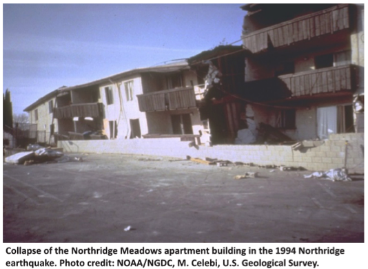
1994-northridge

The survey also serves as a valuable reference in being able to identify and understand what the known vulnerable buildings types are:

  1. Unreinforced masonry buildings: brick or masonry block buildings with no internal steel reinforcement — susceptible to collapse
  2. Wood-frame buildings with raised foundations: single-family homes not properly anchored to the foundation and/or built with a crawl space under the first floor — possible collapse of crawl space cripple walls or sliding off foundation
  3. Tilt-up concrete buildings: concrete walls connected to a wood roof — possible roof-to-wall connection failures leading to roof collapse
  4. Non-ductile reinforced concrete buildings: concrete buildings with insufficient steel reinforcement — susceptible to cracking and damage
  5. Soft first-story buildings: buildings with large openings in the first floor walls, typically for a garage — susceptible to collapse of the first story
  6. Pre-1994 steel moment frame buildings: steel frame buildings built before the 1994 Northridge earthquake with connections — susceptible to cracking leading to potential collapse
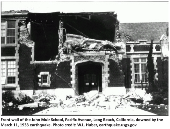
1933-earthquake-shot

Along with the comprehensive list of potentially dangerous buildings, the survey also offers key recommendations on how cities can directly address these hazards and reduce potential risks due to earthquakes. As a good starting point, the survey recommends having “…an active or planned program to assess the building inventory to gauge the number and locations of potentially vulnerable buildings…is one of the first steps in developing appropriate and prioritized risk mitigation and resilience strategies.

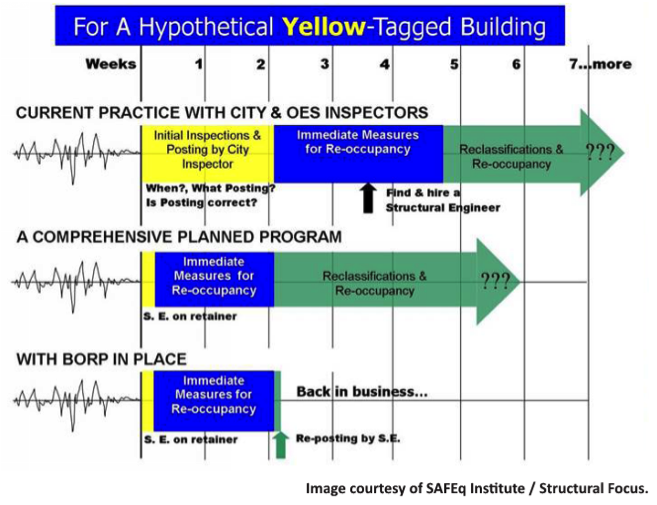
Economic costs can be substantial for businesses whose buildings have been affected by an earthquake. After a major seismic event, a structure needs to be cleared by the building department as safe before it can be reoccupied, and it will generally receive a green (safe), yellow (moderately damaged) or red (dangerous) tag.  A typical yellow-tagged building could take up to two months to be inspected, repaired and then cleared, meaning an enormous absence of income for businesses. The survey offers a strategy for getting businesses up and running quickly after an earthquake, in order to minimize such losses. The Safer Cities Survey recommends that cities adopt a “Back-to-Business” or “Building Re-Occupancy” program, which would “create partnerships between private parties and the City to allow rapid review of buildings in concert with City safety assessments…Back-to-Business programs…[allow] private parties to activate pre-qualified assessment teams, who became familiar with specific buildings to shorten evaluation time [and] support city inspections.

oes-inspectors-program

Basically, a program like this would allow a property owner to work with a structural engineer before an earthquake occurs. This way, the engineer is familiar with the building’s layout and potential risks, and can plan for addressing any potential damage. Having a program like this in place can dramatically shorten the recovery time for a business, from two months down to perhaps two weeks. Several cities have already adopted these types of programs, including San Francisco and Glendale, and it showed up as a component of Los Angeles’ Resilience by Design report.

Ultimately, the survey found that only a handful of cities have adopted any retrofit ordinance, but many cities indicated they were interested in learning more about how they could get started on the process. As a result, SEAOSC has launched a Safer Cities Advisory Program, which offers expert technical advice for any city looking to enact building retrofit ordinances and programs. This collaboration will hopefully help increase the momentum of strengthening southern California so that it can rebound more quickly from the next “Big One.”

We all want to minimize the risk in our lives, so let’s support our local structural engineering associations and building departments in exploring and enacting seismic building ordinances that benefit the entire community.

For additional information or articles of interest, please visit:

Use Strong-Wall® Shearwall Selector to Design Shearwalls

In time for spring and summer 2017 construction projects, Simpson Strong-Tie has launched the newest version of the Strong-Wall Shearwall Selector for use with engineered design. The latest release is an easy-to-use Web-based application (that’s right, no software to download) that has been updated to comply with the 2015 IBC and now provides solutions for all three Strong-Wall Shearwall types: the Steel Strong-Wall® shearwall (SSW), the Strong-Wall wood shearwall (WSW) and the wood Strong-wall shearwall (SW). If you are familiar with the Strong-Wall Shearwall Selector, you can begin using the web application immediately. For those of you who would like to know more about the web app, please read on.Continue Reading

New Moment-Resisting Post Base

Jhakak Vasavada

Jhalak Vasavada is currently a Research & Development Engineer for Simpson Strong-Tie. She has a bachelor’s degree in civil engineering from Maharaja Sayajirao (M.S.) University of Baroda, Gujarat, India, and a master’s degree in structural engineering from Illinois Institute of Technology, Chicago, IL. After graduation, she worked for an environmental consulting firm called TriHydro Corporation and as a structural engineer with Sargent & Lundy, LLC, based in Chicago, IL. She worked on the design of power plant structures such as chimney foundations, boiler building and turbine building steel design and design of flue gas ductwork. She is a registered Professional Engineer in the State of Michigan.

At Simpson Strong-Tie, we strive to make an engineer’s life easier by developing products that help with design efficiency. Our products are designed and tested to the highest standards, and that gives structural engineers the confidence that they’re using the best product for their application.

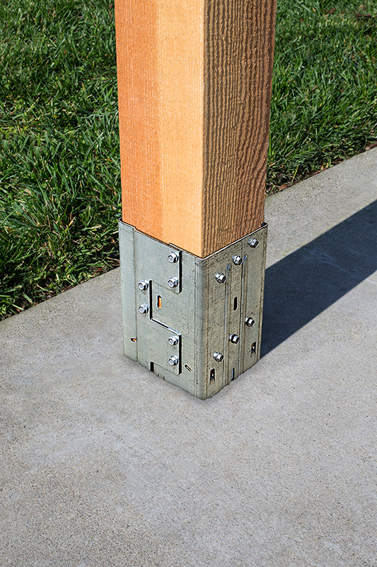
Installed MPBZ
Figure 1: Installed MPBZ

Having worked in the design industry for almost a decade, I can attest that having a catalog where you can select a product that solves an engineer’s design dilemma can be a huge time- and money-saving tool. Design engineers are always trying to create efficient designs, although cost and schedule are always constraints. Moment connections can be very efficient — provided they are designed and detailed correctly. With that in mind, we developed a moment post base connector that can resist moment in addition to download, uplift and lateral loads. In this post, I would like to talk about moment-resisting/fixed connections for post bases and also talk about the product design process.

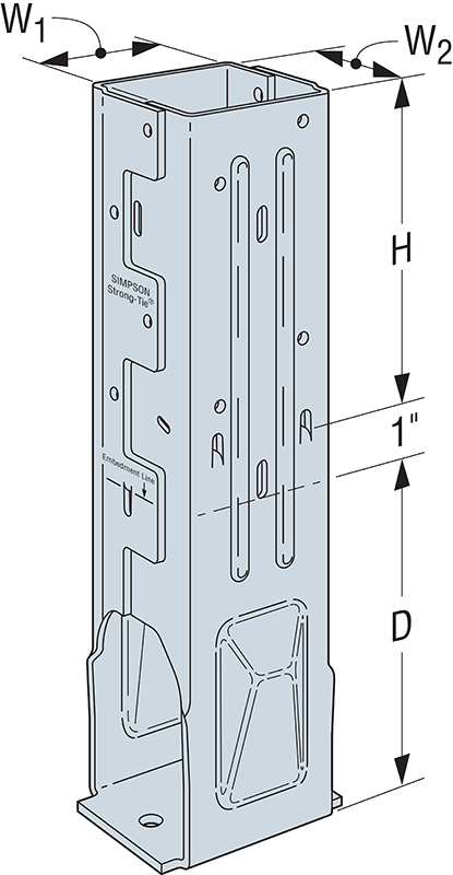
Figure 2. MPB44Z Graphic

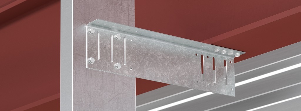
Lateral forces from wind and seismic loads on a structure are typically resisted by a lateral-force-resisting system. There are three main systems used for ordinary rectangular structures: (a) braced frames, (b) moment frames and (c) shearwalls. Moment frames resist lateral forces through bending in the frame members. Moment frames allow for open frames by eliminating the need for vertical bracing or knee bracing. Moment resistance or fixity at the column base is achieved by providing translational and rotational resistance. The new patent-pending Simpson Strong-Tie® MPBZ moment post base is specifically designed to provide moment resistance for columns and posts. An innovative overlapping sleeve design encapsulates the post, helping to resist rotation at its base.

The allowable loads we publish have what I call “triple backup.” This backup consists of Finite Element Analysis (FEA), code-compliant calculations and test data. Here are descriptions of what I mean by that.

Finite Element Analysis Confirmation

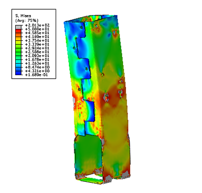
Once a preliminary design for the product is developed, FEA is performed to confirm that the product behaves as we expect it to in different load conditions. Several iterations are run to come up with the most efficient design.

Figure 3. FEA Output of Preliminary MPB Conceptual Design

Code-Compliance Calculations

Load calculations are prepared in accordance with the latest industry standards. The connector limit states are calculated for the wood-post-to-MPBZ connection and for MPBZ anchorage in concrete. Steel tensile strength is determined in accordance with ICC-ES AC398 and AISI S100-07. Wood connection strength is determined in accordance with ICC-ES AC398 and AC13. Fastener design is analyzed as per NDS. SDS screw values are analyzed using known allowable values per code report ESR-2236. The available moment capacity of the post base fastened to the wood member is calculated in accordance with the applicable bearing capacity of the post and lateral design strength of the fasteners per the NDS or ESR values. Concrete anchorage pull-out strength is determined in accordance with AC398.

Test Data Verification

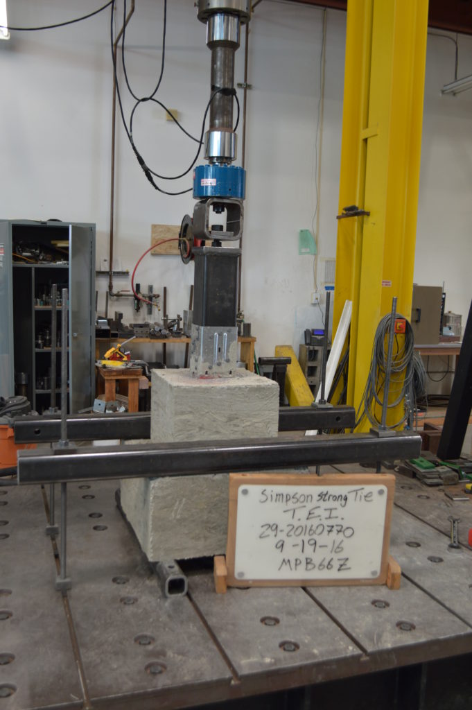
The moment post base is tested for anchorage in both cracked and uncracked concrete in accordance with ICC-ES AC398.

Figure 4. Uplift Test Setup

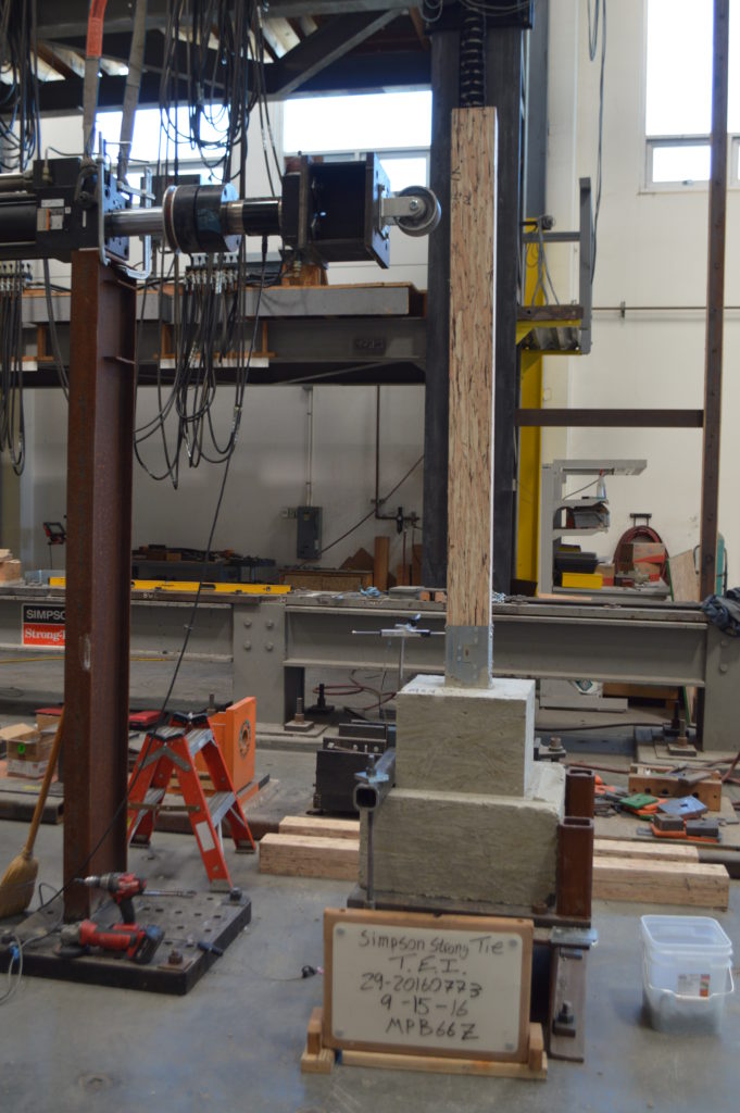
The moment post base assembly is tested for connection strength in accordance with ICC-ES AC13.

Figure 5: Moment (induced by lateral load application) Test Set Up

The assembly (post and MPBZ) is tested for various loading conditions: download, uplift and lateral load in both orthographic directions and moment. Applicable factor(s) of safety are applied, and the controlling load for each load condition is published in the Simpson Strong-Tie Wood Construction Connectors Catalog.

Now let’s take a look at a sign post base design example to see how the MPBZ data can be used.

Design Example:

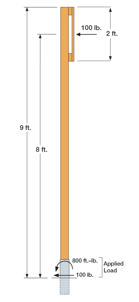
Figure 6: Sign Post Base Design Example

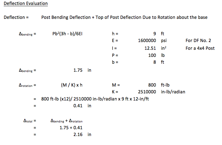
The MPB44Z is used to support a 9ʹ-tall 4×4 post with a 2ʹ x 2ʹ sign mounted at the top. The wind load acting on the surface of the sign is determined to be 100 lb. The MPB44Z is installed into concrete that is assumed to be cracked.

  • The design lateral load due to wind at the MPB44Z is 100 lb.
  • The design moment due to wind at the MPB44Z is (100 lb.) x (8 ft.) = 800 ft.-lb.
  • The Allowable Loads for the MPB44Z are:
    • Lateral (F1) = 1,280 lb.
    • Moment (M) = 985 ft.-lb.
  • Simultaneous Load Check:
    • 800/985 + 100/1,280 = 0.89. This is less than 1.0 and is therefore acceptable.

mpbz-deflection-evaultion

We are very excited about our new MPBZ! We hope that this product will get you excited about your next open-structure design. Let us know your thoughts by providing comments here.

Considerations for Designing Anchorage in Proximity to Abandoned Anchor Holes

danharmon.headshot.finalThis week’s post comes from Dan Harmon, an R&D engineer for Simpson Strong-Tie’s Infrastructure-Commercial-Industrial (ICI) group. Dan specializes in post-installed concrete anchor design and spent a decade managing Simpson’s anchor testing lab, where he developed extensive knowledge of anchor behavior and performance. He has a Bachelor of Science in mechanical engineering from the University of Illinois Urbana-Champaign.

Designers and engineers can spend hundreds of hours on detailed drawings of structures, but there are often conditions and coordination that can change well-planned details and drawings. As we all know, paper and reality don’t always agree. Anchorage locations can move as a result of unforeseen circumstances such as encountering reinforcing bars in an existing concrete slab or interference between different utility trades.

With post-installed anchors, one particular jobsite change may require abandoning a hole that has been drilled, leaving the final anchor location adjacent to the abandoned hole. When a hole for an anchor is drilled but never used, it essentially creates a large void in the concrete. Depending on where this void is located in relation to an installed anchor, there is potential for the capacity of that anchor to be reduced. To give guidance on this situation to specifiers, users and contractors, Simpson Strong-Tie conducted a large series of tests in their ISO 17025–accredited Anchor Systems Test Lab in Addison, Illinois.

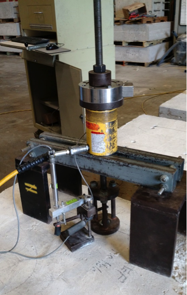
To evaluate the effect of abandoned holes located adjacent to post-installed anchors, we performed tension tests meeting the requirements of ASTM E488-15 (see Figure 1). A variety of anchor types with common diameters were tested:

  • Drop-in anchors (1/2″ and 3/4″ diameter)
  • Wedge-type anchors (1/2″ and 3/4″ diameter)
  • Concrete screws (1/2″ diameter)
  • Adhesive anchors with threaded rod (1/2″ diameter)
Figure 1: Common Unconfined Tension Test Set-Up per ASTM E488-15

Each anchor type and diameter was tested under five different conditions:

  • No abandoned hole near the installed anchor. This is considered the reference condition to which other tests are to be compared.
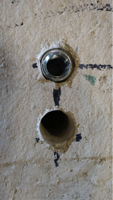
  • One abandoned hole at a distance of two times the hole diameter (2d) away from the installed anchor. See Figure 2.
  • One abandoned hole at a distance of four times the hole diameter (4d) away from the installed anchor.
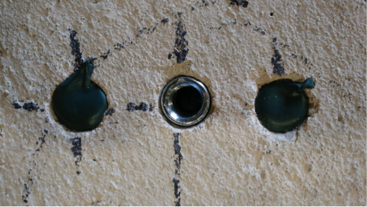
  • Two abandoned holes, each at a distance of two times the hole diameter (2d) away from the installed anchor. In test conditions with two holes, the holes were located on either side of the installed anchor, approximately 180º from each other. See Figure 3.
  • Two abandoned holes, each at a distance of two times the hole diameter (2d) away from the installed anchor, with the holes refilled with a concrete anchoring adhesive that was allowed to cure fully prior to testing. See Figure 4.
Figure 2: Drop-In Anchor with a Single Hole at a Distance of 2d
Figure 3: Drop-In Anchor with Two Holes at a Distance of 2d
Figure 4: Drop-In Anchor with Two Holes, Filled with Anchoring Adhesive, at a Distance of 2d

This test program is summarized in Table 1. In all cases, the abandoned hole was of the same diameter and depth as the hole prescribed for the installed anchor.

Table 1. Summary of Test Program

Five tests for each anchor under each condition were tested, and the mean and coefficient of variance of each data set were calculated. These calculated values were used to compare the different conditions.

Across the different anchor types and diameters, the test results showed a number of general rules that held true.

Summary Results

Abandoned holes that are 2” or more away from the anchor have little to no effect on the tension performance of the anchor. Compared to the reference condition with no abandoned hole near the anchor, conditions where the abandoned hole was sufficiently far away were found to be essentially equivalent. This equivalence held true even for anchor types that create expansion forces (drop-in and wedge-type anchors) during their installation.

Two abandoned holes have the same effect on performances as one, regardless of distance from the anchor. This testing showed that adding a second abandoned hole near an installed anchor did not adversely affect tension performance in a significant way. Even within distances of 2 inches, performance did not drop substantially – if at all – in conditions involving two abandoned holes as compared to one.

Filling abandoned holes with an anchoring adhesive prior to installation of the anchor improves performance. In all cases tested, filling abandoned holes with adhesives resulted in increased performance compared to leaving the holes empty. In a majority of cases, performance with filled holes was equivalent to performance in the reference condition regardless of the distance from the anchor.

When the abandoned hole is more than two times the drilled hole diameter but less than 2″from the anchor – and left unfilled – the testing showed a loss in performance. Not surprisingly, the degree of that loss was dependent on the type of anchor. Table 2 shows the capacity reduction compared to the reference condition in testing with expansion anchors. Table 3 shows the same results for concrete screws and adhesive anchors. Conservative suggested performance reductions in these conditions would be 20% for expansion anchors and 10% for concrete screws and adhesive anchors.

Table 2: Performance Reduction for Expansion Anchors
Table 3: Performance Reduction for Concrete Screws and Adhesive Anchors

In an ideal world, the engineer’s designs could be followed at all times at the jobsite. But we don’t live in an ideal world. Good engineering judgment is needed in situations where variation is required, and having data to support those decisions is always helpful. In the case of abandoned holes near post-installed anchors, it’s Simpson Strong-Tie’s hope that this testing provides additional guidance for the designer, inspector, and jobsite worker.


Top Three Reasons Why Structural Engineers Should Attend Webinars

We encourage all our employees to always keep learning and seeking out resources that can stimulate new ideas or help improve processes in their jobs. Webinars are a great way for you to stay engaged in your profession and learn new things about the industry. They mix the convenience of online availability with the interactivity of live seminars, and because some are free or offered at a much lower cost than live trainings, they make it even easier to stay up to date on current issues in your field. Our top three reasons why you should attend structural engineering webinars are below:

Close up shot of webinar on a laptop.

Some Webinars Offer Continuing Education Credits

Webinars for structural engineers can be very useful for staying current with professional development requirements. Look to see if the webinar you are interested in attending offers credits. Simpson Strong-Tie offers a wide range of webinars that allow structural engineers to earn CEU and PDH credits. There are plenty of other professional organizations that offer accredited webinars for structural engineers, also. Paul McEntee shares his list of recommended professional resources (including webinars) for structural engineers here.

Learn About Code Changes and Requirements

Staying up to date on code changes and requirements is one of the reasons why continuing education is so important. The Structural Engineers Association of California (SEAOC) has a helpful lunchtime webinar series that delves into 2015 International Building Code (IBC) changes. Simpson Strong-Tie webinars always review current code requirements for the kinds of structural design under discussion. For example, the Best Practices on Prefabricated Wood Shearwall Design webinar covers code reports on shearwall applications.

Learn About the Latest Products and Technology

 If you can’t make it to a live training session, using webinars to learn about the most recent products and technology is an effective way to stay current in the field. Whether you want to learn about the latest in prefabricated Strong-Wall® Shearwall panels or to gain fuller understanding of Best Practices for FRP Strengthening Design, webinars can help you design using the most advanced technology.

What was the best webinar you’ve attended? Why was it so good, or what was it you learned? Let us know in the comments below.

Q&A: Best Practices for FRP Strengthening Design

frp-design-banner
On December 1, 2016, Simpson Strong-Tie hosted a webinar titled “The Design Fundamentals of FRP Strengthening” in which Justin Streim, P.E. – one of our Field Engineers – and I discussed the best practices for fiber-reinforced polymer (FRP) strengthening design. The webinar examines FRP components, applications and installation. It also features an example of the evaluation that went into a flexural-beam-strengthening design and discusses the assistance and support Simpson Strong-Tie Engineering Services offers from initial project assessment to installation. Watch the on-demand webinar and earn PDH and CEU credits here.
During the live webinar, we had the pleasure of presenting to more than 1,500 engineers who asked nearly 300 questions during the Q&A session. Here is a curated selection of Q&A from that session:
q-a-graphic
Can you discuss the flexural strengthening for reinforced masonry walls?
Out-of-plane flexural strengthening can be provided with FRP on the required face of wall. In-plane (or shear wall type) flexural strengthening can also be provided with vertical FRP strips near the ends of walls.
In general, by what percentage can FRP solutions increase the strength of existing concrete shearwalls?
This really depends on the existing wall, but we have seen strength increases of 22% in our testing of one layer of glass fabric installed on 8″ thick ungrouted CMU shearwall.
How does FRP compete in terms of cost? It seems like a cost-prohibitive solution compared to other remediation techniques in the absence of other limiting factors (space limitations, etc.).
FRP may be expensive on a cost/SF basis. However, if you compare it with the materials and labor involved in section enlargement or demolishing parts of buildings, it becomes cost effective. FRP installations are also not unsightly like bolted steel plates or wide flange members slung under concrete slabs/beams.
Who designs the FRP system: Simpson Strong-Tie or the Structural Designer?
The Simpson Strong-Tie Engineering Services group provides the FRP design on most projects, but we have also worked with the engineer on record (EOR) to check their FRP design on projects.
Are there any deformation compatibility issues between carbon fiber or glass and existing reinforcing bar that need to be accounted for in design? Is long-term creep similar to that seen with reinforcing bar?
CFRP and GFRP have different elastic moduli from each other and from steel. When designing an FRP strengthening solution, these differences must be taken into account. For flexural applications, the FRP should be designed to fail from debonding after the internal rebar begins to yield. Creep is taken into account in design equations through reduction factors and stress checks.
Will ACI 440 be updated to include the use of FRP with post-tensioned beams (i.e., unbonded tendons)? Does Simpson Strong-Tie do all stress checks based on gross section properties when total stress is < 12sqrtf’c?
Yes, there is an ACI 440 committee working on including an unbonded PT section in ACI 440.2R. We will work with the EOR to determine what section properties are most appropriate for the specific member being evaluated.
Can you increase deflection limits with FRP?
While FRP does help to limit deflection in members, members with deflection issues are not typically candidates for FRP repair. Prestressed laminates as used in Europe would be a better solution for a member with deflection issues. We do not currently offer prestressed laminates but may in the future.
Does an aesthetic coating interfere with bridge inspection? What is inspection looking for? Delamination or other defects?
A coating could interfere with a visual inspection of the FRP surface. A visual inspection can reveal changes in color, debonding, peeling, blistering, cracking, crazing, deflections, indications of reinforcing-bar corrosion, and other anomalies. In addition, ultrasonic, acoustic sounding (hammer tap) and thermographic tests may indicate signs of progressive delamination. ACI 440 and AC 178 have extensive special inspection recommendations.

Learn more: Webinar – Introducing Fabric-Reinforced Cementitious Matrix (FRCM)

In this free webinar we dive into some very important considerations including the latest industry standards, material properties and key governing limits when designing with FRCM.
Continuing education credits will be offered for this webinar.
Participants can earn one professional development hour (PDH) or 0.1 continuing education unit (CEU).

For complete information regarding specific products suitable to your unique situation or condition, please visit strongtie.com/css or call your local Simpson Strong-Tie RPS specialist at (800) 999-5099.
 

Q&A: Best Practices for FRP Strengthening Design

frp-design-banner

On December 1, 2016, Simpson Strong-Tie hosted a webinar titled “The Design Fundamentals of FRP Strengthening” in which Justin Streim, P.E. – one of our Field Engineers – and I discussed the best practices for fiber-reinforced polymer (FRP) strengthening design. The webinar examines FRP components, applications and installation. It also features an example of the evaluation that went into a flexural-beam-strengthening design and discusses the assistance and support Simpson Strong-Tie Engineering Services offers from initial project assessment to installation. Watch the on-demand webinar and earn PDH and CEU credits here.

During the live webinar, we had the pleasure of presenting to more than 1,500 engineers who asked nearly 300 questions during the Q&A session. Here is a curated selection of Q&A from that session:

q-a-graphic

Can you discuss the flexural strengthening for reinforced masonry walls?

Out-of-plane flexural strengthening can be provided with FRP on the required face of wall. In-plane (or shear wall type) flexural strengthening can also be provided with vertical FRP strips near the ends of walls.

In general, by what percentage can FRP solutions increase the strength of existing concrete shearwalls?

This really depends on the existing wall, but we have seen strength increases of 22% in our testing of one layer of glass fabric installed on 8″ thick ungrouted CMU shearwall.

How does FRP compete in terms of cost? It seems like a cost-prohibitive solution compared to other remediation techniques in the absence of other limiting factors (space limitations, etc.).

FRP may be expensive on a cost/SF basis. However, if you compare it with the materials and labor involved in section enlargement or demolishing parts of buildings, it becomes cost effective. FRP installations are also not unsightly like bolted steel plates or wide flange members slung under concrete slabs/beams.

Who designs the FRP system: Simpson Strong-Tie or the Structural Designer?

The Simpson Strong-Tie Engineering Services group provides the FRP design on most projects, but we have also worked with the engineer on record (EOR) to check their FRP design on projects.

Are there any deformation compatibility issues between carbon fiber or glass and existing reinforcing bar that need to be accounted for in design? Is long-term creep similar to that seen with reinforcing bar?

CFRP and GFRP have different elastic moduli from each other and from steel. When designing an FRP strengthening solution, these differences must be taken into account. For flexural applications, the FRP should be designed to fail from debonding after the internal rebar begins to yield. Creep is taken into account in design equations through reduction factors and stress checks.

Will ACI 440 be updated to include the use of FRP with post-tensioned beams (i.e., unbonded tendons)? Does Simpson Strong-Tie do all stress checks based on gross section properties when total stress is < 12sqrtf’c?

Yes, there is an ACI 440 committee working on including an unbonded PT section in ACI 440.2R. We will work with the EOR to determine what section properties are most appropriate for the specific member being evaluated.

Can you increase deflection limits with FRP?

While FRP does help to limit deflection in members, members with deflection issues are not typically candidates for FRP repair. Prestressed laminates as used in Europe would be a better solution for a member with deflection issues. We do not currently offer prestressed laminates but may in the future.

Does an aesthetic coating interfere with bridge inspection? What is inspection looking for? Delamination or other defects?

A coating could interfere with a visual inspection of the FRP surface. A visual inspection can reveal changes in color, debonding, peeling, blistering, cracking, crazing, deflections, indications of reinforcing-bar corrosion, and other anomalies. In addition, ultrasonic, acoustic sounding (hammer tap) and thermographic tests may indicate signs of progressive delamination. ACI 440 and AC 178 have extensive special inspection recommendations.

Learn more: Webinar – Introducing Fabric-Reinforced Cementitious Matrix (FRCM)

In this free webinar we dive into some very important considerations including the latest industry standards, material properties and key governing limits when designing with FRCM.

Continuing education credits will be offered for this webinar.
Participants can earn one professional development hour (PDH) or 0.1 continuing education unit (CEU).


For complete information regarding specific products suitable to your unique situation or condition, please visit strongtie.com/css or call your local Simpson Strong-Tie RPS specialist at (800) 999-5099.


Three Pieces of Advice for Structural Engineering Grads

If you are a civil engineering student finishing your degree, you are probably starting to explore all the options and opportunities available in the workforce. While structural engineering may be a specialized discipline, there are many paths and backgrounds that can lead someone into an exciting career that is innovatively transforming modern development in cities and towns all over the world.Continue Reading