

Structural engineering, like every other research field, advances by educating new generations of students in the principles and practice of the discipline. Knowing that, Simpson Strong-Tie has teamed with the Binational Softwood Lumber Council and the American Wood Council to co-sponsor and coordinate the Timber Strong Design-Build Competition, an annual design contest held at the ASCE Pacific Southwest Conference in Tempe, Arizona.
Engineering students will test their civil and environmental engineering skills this spring when they compete in the annual Timber Strong Design-Build Competition. Eighteen universities will send teams of students to Tempe, Arizona, to participate at the American Society of Civil Engineers (ASCE) Pacific Southwest Conference (PSWC).
The objective of the competition, taking place April 12–14, is to give students valuable real-world engineering design experience:
Continue Reading
Tag: American Wood Council

Designing Gable End Overhangs
It seems that each major hurricane tends to teach those of us in the construction industry some lesson. With Hurricane Andrew, the lessons were the importance of protection from windborne debris, and the importance of proper construction of gable end overhangs.
There are two main areas where gable ends can fail.
Mass Timber Construction – Building for the Future
The future is here and that future is mass timber construction.
It is common knowledge that wood is a renewable and environmentally friendly building material. There are two types of wood-framing methods in North America. The most common method for residential construction is light-frame construction using either balloon-framing or platform-framing methods. Standardized dimensional lumber has become the dominant building material in light-frame construction because of its economy. The other method is heavy-timber construction, which often uses large solid-wood sections for nonresidential construction, such as for storage, mercantile and industrial buildings.
In Europe, there is a trend to create larger “laminated” wood sections using the more traditional standardized dimensional lumber of the 1990s. This trend culminated in what is now classified as cross-laminated timber, or CLT. CLT can be used to create floor panels and roof panels. In North America, this is classified either as cross-laminated timber (CLT) or generically as mass timber.
CLT is essentially multiple layers of wood panels. Each layer of wooden panels is laid crosswise on the one before at approximately a 90° angle and glued using a polyurethane adhesive to increase the stability of the entire panel. Typical thickness of the individual boards can vary from 3/8″ to 2″ thick. Typical board width can vary from 2-3/8” to 9-1/2” wide. CLT panels are fabricated and marketed from 3-ply CLT up to 7-ply CLT. CLT 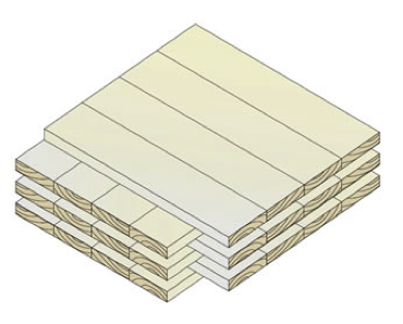 manufacturers normally publish characteristic properties for their panels – such as bending strength, shear strength, modulus of elasticity and panel stiffness – to assist Designers in specifying these products.
A Cross Laminated Timber Handbook has been published by FPInnovations in Canada as an introduction to CLT. The US edition CLT handbook can be downloaded for free here.
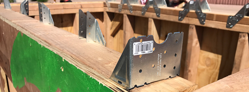
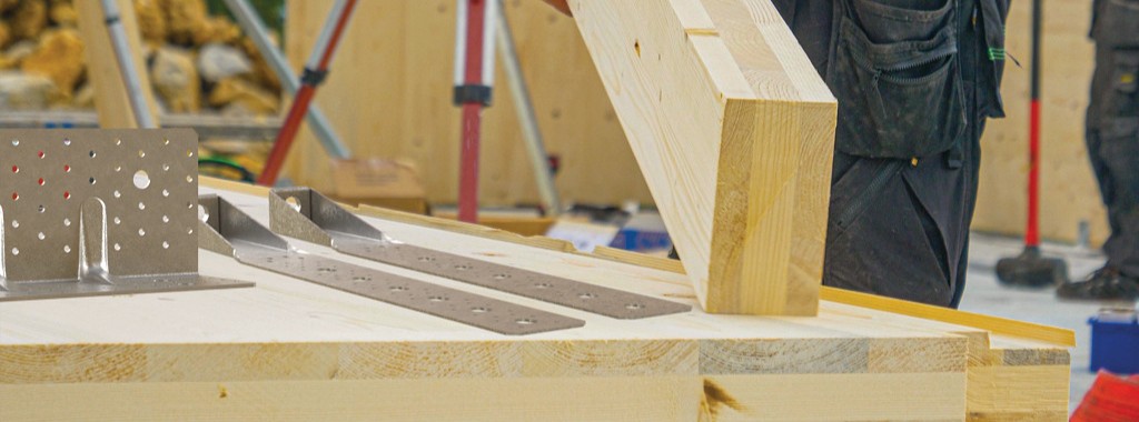
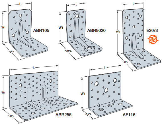
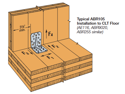
As in all wood buildings, connection designs are critical to the success of this new type of building material. Simpson Strong-Tie offices in Europe have been instrumental in developing and supplying connectors and fasteners in the CLT market. Simpson Strong-Tie has developed many connectors specifically for the CLT market in Europe (Figure 3).
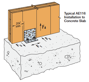
Those connectors are used to join the CLT floor panels to CLT wall panels and CLT wall panels to the concrete foundation (Figures 1 and 2).
 Specialized ring-shank nails and long metal screws have been developed as well. In mid-2014, Simpson Strong-Tie North America (Pleasanton, California Testing Facility) embarked on an initial test program to assess those connectors and fasteners developed for the CLT market by Simpson Strong-Tie Europe, using North American CLT panels to verify and quantify the performance characteristics according to North American testing protocols (American Society for Testing and Materials and Canadian Construction Materials Centre).
The initial test program used CLT panels fabricated in Western Canada using Canadian Spruce-Pine-Fir (S-P-F) lumber. The connectors and ring-shank nails were imported from the Simpson Strong-Tie European manufacturing facilities. Testing of the connectors also included the Simpson Strong-Tie Strong-Drive® SD screws, which as expected, provided higher load capacity than the ring-shank nails. A summary of the test program and the load rating developed for both the Canadian and the U.S. market can be downloaded here.
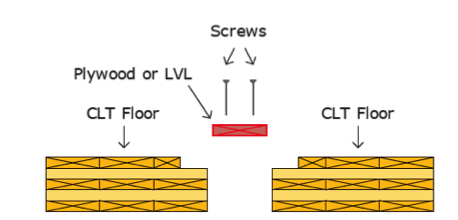
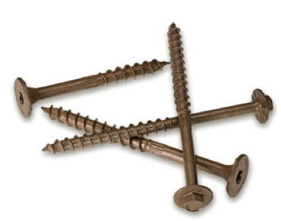
Other types of long countersunk screws such as the Strong-Drive® SDWS Timber screw (countersunk) or Strong-Drive SDWH Timber-Hex (hex head) screw (shown) are used either to splice the floor panels together or to drag the diaphragm loads back to the column or post as necessary.
As CLT continues to gain acceptance in North America, other connection details will also become more popular. Simpson Strong-Tie intends to continue developing and improving connection details to support this type of construction.
Building code acceptance is another important requirement and development that is in progress in both Canada and the U.S. In Canada, the 2014 edition of CSA O86 “Engineering Design in Wood” has reserved a section for CLT.
The 2015 edition of the International Building Code (IBC) recognized CLT when it is manufactured to the product standard. CLT walls and floors will be permitted in all types of combustible construction. The 2015 National Design Specification (NDS) for Wood Construction was recently published and approved as an ANSI American National Standard. The 2015 National Design Specification is also referenced in the 2015 IBC.
The future is here. Environmentally friendly mass timber (including CLT) is poised to grow in use, especially with the recognition of CLT in the building codes. North American manufacturing of CLT has been established and can only grow to support the expanding use of this new building material.
References:
https://fpinnovations.ca
*Images with permission from FPInnovations

New Treatment of Shear Wall Aspect Ratios in the 2015 SDPWS
This post was co-written by Simpson Engineer Randy Shackelford and AWC Engineer Phil Line.
The 2015 International Building Code references a newly updated 2015 Edition of the American Wood Council Special Design Provisions for Wind and Seismic standard (SDPWS). The updated SDPWS contains new provisions for design of high aspect ratio shear walls. For wood structural panels shear walls, the term high aspect ratio is considered to apply to walls with an aspect ratio greater than 2:1. These same high‑aspect‑ratio shear wall provisions have been maintained in subsequent editions of SDPWS, including the 2021 SDPWS, and remain part of current design practice.

In the 2015 SDPWS, reduction factors for high aspect ratio shear walls are no longer contained in the footnotes to Table 4.3.4 (See Figure 2). Instead, these factors are included in new provisions accounting for the reduced strength and stiffness of high aspect ratio shear walls.

Deflection Compatibility – Calculation Method
New Section 4.3.3.4.1 states that “Shear distribution to individual shear walls in a shear wall line shall provide the same calculated deflection, δsw, in each shear wall.” Using this equal deflection calculation method for distribution of shear, the unit shear assigned to each shear wall within a shear wall line varies based on its stiffness relative to that of the other shear walls in the shear wall line. Thus, a shear wall having relatively low stiffness, as is the case of a high aspect ratio shear wall within a shear wall line containing a longer shear wall, is assigned a reduced unit shear (see Figure 3).
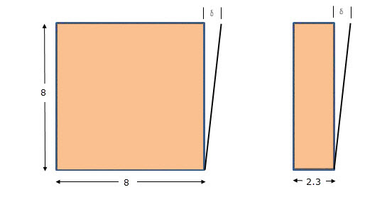
In addition, Section 4.3.4.2 contains a new aspect ratio factor, 1.25 – 0.125h/bs, that specifically accounts for the reduced unit shear capacity of high aspect ratio shear walls. The strength reduction varies linearly from 1.00 for a 2:1 aspect ratio shear wall to 0.81 for a 3.5:1 aspect ratio shear wall. Notably, this strength reduction applies for shear walls resisting either seismic forces or wind forces. For both wind and seismic, the controlling unit shear capacity is the smaller of the values from strength criteria of 4.3.4.2 or deflection compatibility criteria or 4.3.3.4.1.
Deflection Compatibility – 2bs/h Adjustment Factor Method
The 2bs/h factor, previously addressed by footnote 1 of Table 4.3.4, is now an alternative to the equal deflection calculation method of 4.3.3.4.1 and applies to shear walls resisting either wind or seismic forces. This adjustment factor method allows the designer to distribute shear in proportion to shear wall strength provided that shear walls with high aspect ratio have strength adjusted by the 2bs/h factor. The strength reduction varies linearly from 1.00 for 2:1 aspect ratio shear walls to 0.57 for 3.5:1 aspect ratio shear walls. This adjustment factor method provides roughly similar designs to the equal deflection calculation method for a shear wall line comprised of a 1:1 aspect ratio wall segment in combination with a high aspect ratio shear wall segment.
In prior editions of SDPWS, a common misunderstanding was that the 2bs/h factor represented an actual reduction in unit shear capacity for high aspect ratio shear walls as opposed to a reduction factor to account for stiffness compatibility. The actual reduction in unit shear capacity of high aspect ratio shear walls is represented by the factor, 1.25 – 0.125h/bs, as noted previously. The 2bs/h factor is the more severe of the two factors and is not applied simultaneously with the 1.25-0.125h/bs factor.
What are the major implications for design?
- For seismic design, the 2bs/h factor method continues unchanged, but is presented as an alternative to the equal deflection method in 4.3.3.4.1 for providing deflection compatibility. The equal deflection calculation method can produce both more and less efficient designs that may result from the 2bs/h factor method depending on the relative stiffness of shear walls in the wall line. For example, design unit shear for shear wall lines comprised entirely of 3.5:1 aspect ratio shear walls can be as much as 40% greater (i.e. 0.81/0.57=1.42) than prior editions if not limited by seismic drift criteria.
- For wind design, high aspect ratio shear wall factors apply for the first time. For shear walls with 3.5:1 aspect ratio, unit shear capacity is reduced to not more than 81% of that used in prior editions. The actual reduction will vary by actual method used to account for deflection compatibility.
- The equal deflection calculation method is sensitive to many factors in the shear wall deflection calculation including hold-down slip, sheathing type and nailing, and framing moisture content. The familiar 2bs/h factor method for deflection compatibility is less sensitive to factors that affect shear wall deflection calculations and in many cases will produce more efficient designs.
As the 2015 International Building Code is adopted in various jurisdictions, designers will need to be aware of these new requirements for design of high aspect ratio shear walls. The 2015 SDPWS also contains other important revisions that designers should pay attention to. The American Wood Council provides a read-only version of the standard on their website that is available free of charge.
Please contribute your thoughts to these new requirements in the comments below.

Here Come 2015 IBC Changes!
All of us here at Simpson Strong-Tie hope you had a happy and successful 2014. It seems that the folks at the International Code Council had a good year. True to their plan, the 2015 editions of the International Codes were published during the summer so that they are ready for adoption in 2015.

 Simpson Strong-Tie was tracking a number of issues during the development of the 2015 International Building Code and International Residential Code. Here is a summary of some of the significant changes that users will see in the 2015 International Building Code (IBC).
One significant change affecting Simpson Strong-Tie was the removal of the requirements for evaluation of joist hangers and similar devices from Chapter 17, and the revision of Sections 2303.5 and 2304.10.3 to reference ASTM D 7147 as the test standard for joist hangers.
Since the primary reference standard for design in Chapter 16, ASCE 7-10 has not changed; there were not a lot of significant changes in that chapter. The definitions of “Diaphragm, rigid” and “Diaphragm, flexible” were deleted from Chapter 2, and a sentence was added to 1604.4 stating when a diaphragm can be considered rigid, along with a reference to ASCE 7 for determining when designs must account for increased forces from torsion due to eccentricity in the lateral force resisting system.
In Chapter 19, significant improvements were made to the sections that modify ACI 318 so that the IBC and the standard are coordinated, correcting the problems in the 2012 IBC. In addition, Sections 1908 (ASD design of anchorage to concrete) and 1909 (strength design of anchorage to concrete) were deleted to remove any conflict with ACI 318 anchor design methods.
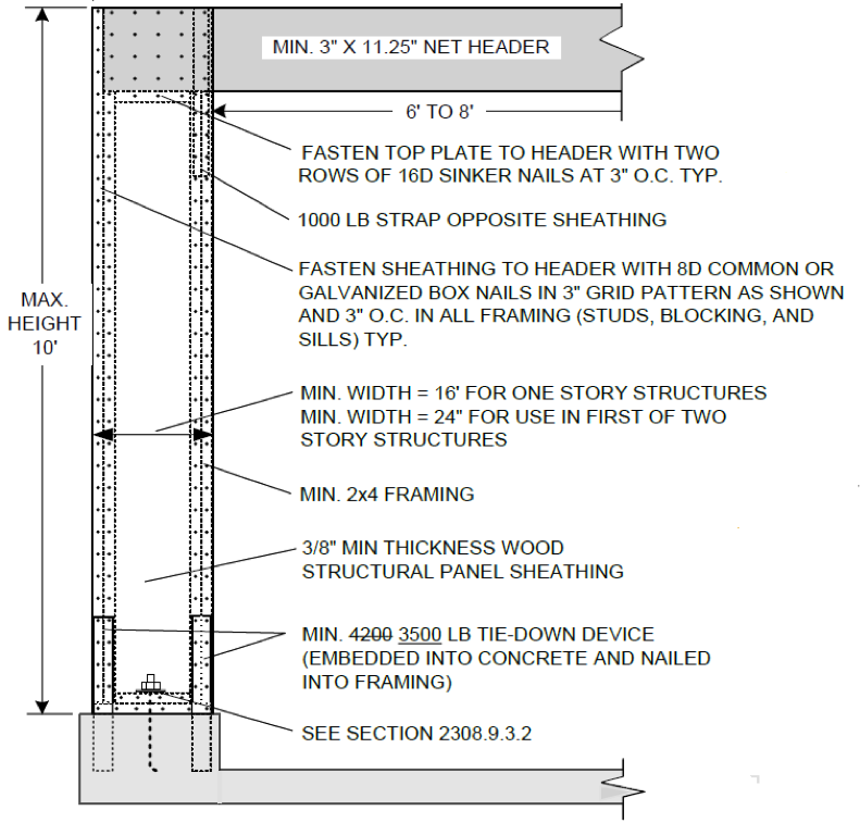
In Chapter 23, a new section was added to address cross-laminated timber, requiring that they be manufactured and identified as required in APA PRG 320. The wood framing fastening schedule was completely reorganized to make it easier to use and the requirements for protection of wood from decay and termites were rewritten. Section 2308 on Conventional Light-Frame Construction was completely reorganized with significant revisions to the wall bracing section. As discussed in an earlier blog post, the holdown requirement for the portal frame with holdowns (now called PFH bracing method in the 2015 IBC) has been reduced from a required capacity of 4,200 pounds to 3,500 pounds.
For designers, some of the most significant changes are in Chapter 35, which lists referenced standards. Some major standards that were updated for this edition of the IBC include ACI318-14, ACI530/530.1-13, several AISI standards (S100-12, S200-12, S214-12, and S220-11), several new and revised ASCE standards (8-14, 24-13, 29-14, 49-07, and 55-10), almost all the AWC standards (WFCM-2015, NDS-2015, STJR-2015, PWF-2015 and SDPWS-2015), AWS D1.4/D1.4M-2011, most NFPA standards (too many to list), PTI DC-10.5-12, SBCA FS 100-12 and TPI 1-14.
Kudos to the American Wood Council. They have posted view-only versions of all their referenced standards online, so designers do not have to buy new editions every time the code changes. AISI also enables one to download PDFs of the framing standards at www.aisistandards.org.
Finally, a couple of ICC Standards were updated to new versions that are referenced in the IBC: ICC-500-14, ICC/NSSA Standard on the Design and Construction of Storm Shelters; and ICC 600-14, Standard for Residential Construction in High-Wind Regions.
A future blog post will cover significant changes in the 2015 IRC. Please share your comments below.