


In my job I get to travel a fair amount. Between trade shows, sales meetings and field research I think I’ve been to most parts of the country in the last few years. One of the things I hear a lot, particularly in areas governed by wind design, is that the last few revisions of the International Residential Code® (IRC®) impose stricter building requirements. As the product manager for our Strong-Wall® shearwalls, I listen with an ear for braced-wall requirements in these areas. There are quite a few different methods of construction called out in Chapter Six of the IRC, and I think I’ve seen them all used in both single-family and multi-family housing, sometimes with multiple types in one structure!
Tag: shearwalls
5 Steps to a Successful Soft-Story Retrofit
Last year, I gave a presentation at the annual National Council of Structural Engineers Associations (NCSEA) Summit in Orlando, Florida, titled “Becoming a Trusted Advisor: Communication and Selling Skills for Structural Engineers.” As this was a summit for the leaders of the structural engineers associations from across the country, I wasn’t sure how many people would find it valuable to spend their time learning about a very nontechnical topic. To my surprise and delight, the seminar ended up being standing-room only, and I was able to field some great questions from the audience about how they could improve their selling and communication skills. In the many conversations I had with the conference attendees after my presentation, the common theme was that engineers felt they needed more soft-skills training in order to better serve their clients. The problem, however, was finding the time to do so when faced with the daily grind of design work.

When I started my first job as a design engineer at a structural engineering consulting firm straight out of school, I was very focused on improving and expanding my technical expertise. Whenever possible, I would attend building-code seminars, design reviews and new product solution presentations, all in an effort to learn more about structural engineering. What I found as I progressed through my career, however, was that no matter how much I learned or how hardworking I was, it didn’t really matter if I couldn’t successfully convey my knowledge or ideas to the person who really mattered most: the client.

How can an engineer be most effective in explaining a proposed action or solution to a client? You have to be able to effectively sell your idea by understanding the needs of your client as well as any reasons for hesitation. The importance of effective communication and persuasion is probably intuitive to anyone who’s been on the sales side of the business, but not something that occurs naturally to data-driven folks like engineers. As a result of recent legislation in California, however, structural engineers are starting to be inundated with questions from a group of folks who have suddenly found themselves responsible for seismically upgrading their properties: apartment building owners in San Francisco and Los Angeles.
Imagine for a moment that you are a building owner who has received a soft-story retrofit notice under the City of Los Angeles’ Ordinance 183893; you have zero knowledge of structural engineering or what this term “soft-story” even means. Who will be your trusted advisor to help you sort it out? The City of Los Angeles Department of Building and Safety (LADBS) has put together a helpful mandatory ordinance website that explains the programs and also offers an FAQ for building owners that lets them know the first step in the process: hire an engineer or architect licensed in the state of California to evaluate the building.

I’ve had the opportunity to be the first point of contact for a building owner after they received a mandatory notice, because it turns out some relatives own an apartment building with soft-story tuck-under parking. Panicked by the notice, they called me looking to understand why they were being forced to retrofit a building that “never had any problems in the past.” They were worried they would lose rent money due to tenants needing to relocate, worried about how to meet the requirements of the ordinance and, most importantly, worried about how much it was going to cost them. What they really wanted was a simple, straightforward answer to their questions, and I did my best to explain the necessity behind retrofitting these vulnerable buildings and give an estimated time frame and cost that I had learned from attending the first Los Angeles Retrofit Resource Fair in April 2016. With close to 18,000 buildings in the cities of San Francisco and Los Angeles alone that have been classified as “soft-story,” this equates to quite a number of building owners who will have similar questions and be searching for answers.
To help provide an additional resource, Simpson Strong-Tie will be hosting a webinar for building owners in the Los Angeles area who have received a mandatory soft-story retrofit notice. Jeff Ellis and I will be covering “5 Steps to a Successful Retrofit” and helping to set a clear project path for building owners. The five steps that Simpson Strong-Tie will be recommending are:
- Understanding the Seismic Retrofit Mandate
- Partnering with Design Professionals
- Submitting Building Plans with the Right Retrofit Product Solutions
- Communicating with Your Building Tenants
- Completing Your Soft-Story Retrofit
We encourage you to invite any clients or potential clients to attend this informative webinar, which will lay the foundation for great communication between the two of you. As part of the webinar, we will be asking the building owners for their comments, questions and feedback so we can better understand what information they need to make informed decisions, and we will be sure to share these with the structural engineering community in a future post. By working together to support better communication and understanding among all stakeholders in retrofit projects, we will be well on our way to creating stronger and more resilient communities!
For additional information or articles of interest, there are several resources available:
- Register for the “5 Steps to a Successful Retrofit” webinar on April 26
- Register to attend the 2nd Los Angeles Seismic Retrofit Resource Fair on April 17 (and stop by the Simpson Strong-Tie booth!)
- Find a structural engineer through the Structural Engineers Association of Southern California (SEAOSC)
- Resilience by Design: City of Los Angeles Lays Out A Seismic Safety Plan
- City of San Francisco Implements Soft-Story Retrofit Ordinance
- Soft-Story Retrofits Using the New Simpson Strong-Tie Retrofit Design Guide
- Visit the Simpson Strong-TieSoft-Story Retrofit Center
- The Los Angeles Times Soft-Story Map
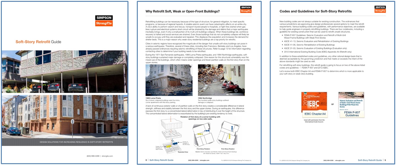
Soft-Story Retrofits Using the New Simpson Strong-Tie Retrofit Design Guide
Thousands of soft-story buildings up and down the West Coast require retrofits to prevent collapse in the event of a major earthquake. Whether the retrofits are mandated by a city ordinance (as in San Francisco, Berkeley and Los Angeles) or are undertaken as voluntary upgrades, the benefits of adding necessary bracing to strengthen the ground story are immense. Simpson Strong-Tie has taken the lead, with our new Soft-Story Retrofit Guide, to provide information that helps engineers find solutions to reinforce soft-story buildings against collapse. We are also providing information on the two methods that can be used for the analysis and design of these soft story retrofits.
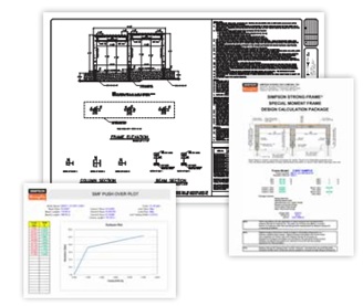
 After the initial information section of the guide, a two-page illustrated spread (pp. 14–15) shows various retrofit products that could be used to retrofit the soft-story structure with reference to the following pages. Three main lateral-force-resisting systems highlighted in this graphic are the Strong Frame® special moment frame (SMF), the new Strong-Wall® wood shearwall, and conventional plywood shearwalls. Individual retrofit components are also shown, such as connection plates and straps for lateral-load transfer, anchors for attachment to the foundation, fasteners and additional products such as the RPBZ retrofit post base and AC post caps for providing a positive connection.
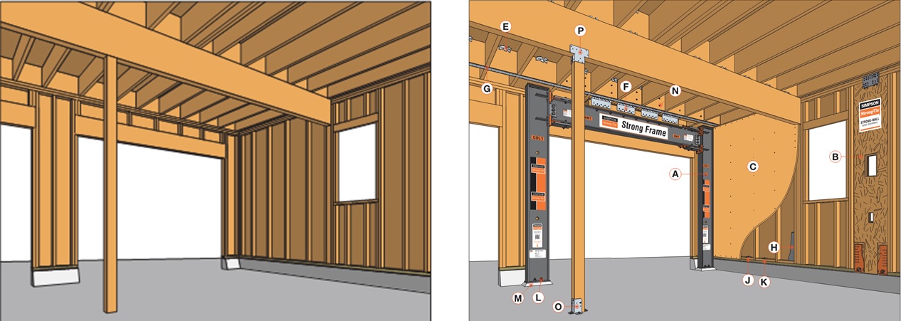 Turning the page, you come to the section describing in detail the many benefits of the Strong-Frame special moment frame (SMF) in a retrofit situation. The engineered performance of the SMF provides the additional strength and ductility that the building requires and can be fine-tuned by selecting various combinations of beams, columns, and Yield-Link® structural fuse sizes. A typical retrofit Strong Frame® SMF comes in three complete pieces allowing for the frame to be installed on the interior of the structure in tight quarters. The frame is simply installed using a 100% snug-tight field-bolted installation with no on-site welding or lateral-beam bracing required.
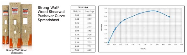
 The next lateral system we focus on is the Strong-Wall® shearwall and the new grade beam solutions offered to reduce the concrete footprint. The new Strong-Wall wood shearwall includes an improved front-access holdown and top-of-wall connection plates for easier installation. Both the Strong Frame SMF and the Strong-Wall wood shearwall have load-drift curves available for use with FEMA P-807. Site-built shearwalls can be installed using retrofit anchor bolts at the mudsill and new holdowns at the shearwall end posts.
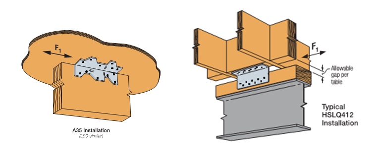
 In the pages following the lateral systems, various products are shown with tabulated LRFD capacities, whereas ASD capacities are typically provided in the order literature for these products. Both ASD and LRFD capacities have been provided for products with new testing values such as the A35 and L90 angles installed with ⅝”-long SPAX screws into three different common floor sheathing materials, as well as for the new HSLQ heavy-shear transfer angle designed to transfer higher lateral forces directly from 4x blocking to the 4x nailer on the Strong-Frame SMF, even when a shim is used between the floor system and the frame. LRFD capacities are provided in this new Soft-Story Retrofit Guide specifically for use with the FEMA P-807 design methodology. This methodology specifies in section 6.5.1 that:
Load path elements should be designed to develop the full strength and the intended mechanism of the principal wall or frame elements. Therefore, to ensure reliability, appropriate strength reduction factors should be applied to the ultimate strengths of load path elements. Specific criteria may be derived from principles of capacity design or from other codes or standards, such as ASCE/SEI 41 or building code provisions involving the overstrength factor, Ωo.
FEMA P-807 bases the capacity of the retrofit elements on the peak strength. LRFD capacities are provided for various load-path connector products, which can be used to develop the full strength of the lateral-force-resisting element to satisfy this requirement.
 Wrapping up, the guide focuses on the various free design tools and resources available for the evaluation, design and detailing of the soft-story structure retrofit. These tools include the Weak Story Tool with Simpson Strong-Tie® Strong Frame® Moment Frames, Design Tutorials for the WST for both San Francisco– and Los Angeles–style buildings, our Soft-Story Retrofit Training Course offering CEUs, Strong Frame Moment Frame Selector Software, Anchor Designer™ Software for ACI 318, ETAG and CSA, and tailored frame solutions using our free engineering services.
 For other information regarding soft-story retrofits, refer to previous blogs in “Soft-Story Retrofits,” “City of San Francisco Implements Soft-Story Retrofit Ordinance,” and “Applying new FEMA P-807 Weak Story Tool to Soft-Story Retrofit.”
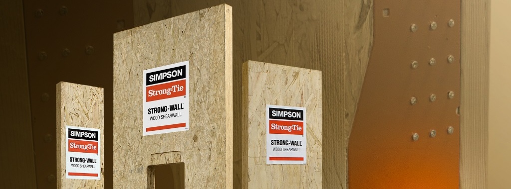
Simpson Strong-Tie® Strong-Wall® Wood Shearwall – The Latest in Our Prefabricated Shearwall Panel Line Part 2
In last week’s blog post, we introduced the Simpson Strong-Tie® Strong-Wall® Wood Shearwall. Let’s now take a step back and understand how we evaluate a prefabricated shear panel to begin with.
First, we start with the International Building Code (IBC) or applicable state or regional building code. We would be directed to ASCE7 to determine wind and seismic design requirements as applicable. In particular, this would entail determination of the seismic design coefficients, including the response modification factor, R, overstrength factor, Ωo, and deflection amplification factor, Cd, for the applicable seismic-force-resisting system. Then back to the IBC for the applicable building material: Chapter 23 covers Wood. Here, we would be referred to AWC’s Special Design Provisions for Wind and Seismic (SDPWS) if we’re designing a lateral-force-resisting system to resist wind and seismic forces using traditional site-built methods.Continue Reading

Simpson Strong-Tie® Strong-Wall® Wood Shearwall – The Latest in Our Prefabricated Shearwall Panel Line Part 1
Some contractors and framers have large hands, which can pose a challenge for them when they’re trying to install the holdown nuts used to attach our Strong-Wall® SB (SWSB) Shearwall product to the foundation. Couple that challenge with the fact that anchorage attachment can only be achieved from the edges of the SWSB panel, and variable site-built framing conditions can limit access depending upon the installation sequence. To alleviate anchorage accessibility issues, we’ve required a gap between the existing adjacent framing and SWSB panel equal to the width of a 2x stud to provide access so the holdown nut can be tightened. Even so, try telling a framer an inch and a half is plenty of room in which to install the nut!Continue Reading
New Treatment of Shear Wall Aspect Ratios in the 2015 SDPWS
This post was co-written by Simpson Engineer Randy Shackelford and AWC Engineer Phil Line.
The 2015 International Building Code references a newly updated 2015 Edition of the American Wood Council Special Design Provisions for Wind and Seismic standard (SDPWS). The updated SDPWS contains new provisions for design of high aspect ratio shear walls. For wood structural panels shear walls, the term high aspect ratio is considered to apply to walls with an aspect ratio greater than 2:1.

In the 2015 SDPWS, reduction factors for high aspect ratio shear walls are no longer contained in the footnotes to Table 4.3.4 (See Figure 2). Instead, these factors are included in new provisions accounting for the reduced strength and stiffness of high aspect ratio shear walls.

Deflection Compatibility – Calculation Method
New Section 4.3.3.4.1 states that “Shear distribution to individual shear walls in a shear wall line shall provide the same calculated deflection, δsw, in each shear wall.” Using this equal deflection calculation method for distribution of shear, the unit shear assigned to each shear wall within a shear wall line varies based on its stiffness relative to that of the other shear walls in the shear wall line. Thus, a shear wall having relatively low stiffness, as is the case of a high aspect ratio shear wall within a shear wall line containing a longer shear wall, is assigned a reduced unit shear (see Figure 3).
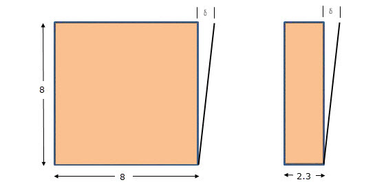
In addition, Section 4.3.4.2 contains a new aspect ratio factor, 1.25 – 0.125h/bs, that specifically accounts for the reduced unit shear capacity of high aspect ratio shear walls. The strength reduction varies linearly from 1.00 for a 2:1 aspect ratio shear wall to 0.81 for a 3.5:1 aspect ratio shear wall. Notably, this strength reduction applies for shear walls resisting either seismic forces or wind forces. For both wind and seismic, the controlling unit shear capacity is the smaller of the values from strength criteria of 4.3.4.2 or deflection compatibility criteria or 4.3.3.4.1.
Deflection Compatibility – 2bs/h Adjustment Factor Method
The 2bs/h factor, previously addressed by footnote 1 of Table 4.3.4, is now an alternative to the equal deflection calculation method of 4.3.3.4.1 and applies to shear walls resisting either wind or seismic forces. This adjustment factor method allows the designer to distribute shear in proportion to shear wall strength provided that shear walls with high aspect ratio have strength adjusted by the 2bs/h factor. The strength reduction varies linearly from 1.00 for 2:1 aspect ratio shear walls to 0.57 for 3.5:1 aspect ratio shear walls. This adjustment factor method provides roughly similar designs to the equal deflection calculation method for a shear wall line comprised of a 1:1 aspect ratio wall segment in combination with a high aspect ratio shear wall segment.
In prior editions of SDPWS, a common misunderstanding was that the 2bs/h factor represented an actual reduction in unit shear capacity for high aspect ratio shear walls as opposed to a reduction factor to account for stiffness compatibility. The actual reduction in unit shear capacity of high aspect ratio shear walls is represented by the factor, 1.25 – 0.125h/bs, as noted previously. The 2bs/h factor is the more severe of the two factors and is not applied simultaneously with the 1.25-0.125h/bs factor.
What are the major implications for design?
- For seismic design, the 2bs/h factor method continues unchanged, but is presented as an alternative to the equal deflection method in 4.3.3.4.1 for providing deflection compatibility. The equal deflection calculation method can produce both more and less efficient designs that may result from the 2bs/h factor method depending on the relative stiffness of shear walls in the wall line. For example, design unit shear for shear wall lines comprised entirely of 3.5:1 aspect ratio shear walls can be as much as 40% greater (i.e. 0.81/0.57=1.42) than prior editions if not limited by seismic drift criteria.
- For wind design, high aspect ratio shear wall factors apply for the first time. For shear walls with 3.5:1 aspect ratio, unit shear capacity is reduced to not more than 81% of that used in prior editions. The actual reduction will vary by actual method used to account for deflection compatibility.
- The equal deflection calculation method is sensitive to many factors in the shear wall deflection calculation including hold-down slip, sheathing type and nailing, and framing moisture content. The familiar 2bs/h factor method for deflection compatibility is less sensitive to factors that affect shear wall deflection calculations and in many cases will produce more efficient designs.
As the 2015 International Building Code is adopted in various jurisdictions, designers will need to be aware of these new requirements for design of high aspect ratio shear walls. The 2015 SDPWS also contains other important revisions that designers should pay attention to. The American Wood Council provides a read-only version of the standard on their website that is available free of charge.
Please contribute your thoughts to these new requirements in the comments below.
Wood Shear Wall Design Example
Two weeks ago, I had the chance to present to the Young Members Group of the Structural Engineering Association of Metro Washington on the topic of Multi-Story Light-Frame Shear Wall Design. With all of the large firms in the D.C. area, it wasn’t a big surprise to find out that only about one-third of the group had experience with light-frame shear wall design.
However, while researching civil/structural engineering programs in the Midwest and Northeast last week (for our Structural Engineering/Architecture Student Scholarship program), I was disappointed to find that only about a quarter of the top engineering programs offer a wood design course. So I thought it might be helpful to post a wood shear wall design example this week.
The example is fairly basic but includes an individual full-height and perforated shear wall analysis for the same condition. The design is based on wind loading and SPF framing, both common in the Midwest/Northeast, and is based on the provisions and terms listed in the 2008 Special Design Provisions for Wind and Seismic (SDPWS), available for free download here, along with the recently posted 2015 version.
Multi-Story Shear Wall Example: Wind Loads with SPF Framing
Given: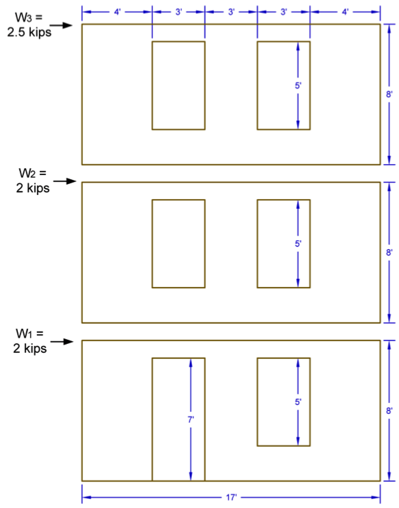
- 2012 IBC & 2008 SDPWS
- 3-Story Wood Framed Shear Wall Line
- ASD Diaphragm Shear Forces from Wind as Shown
- Wall and Opening Dimensions as Shown
Solution:
- Determine total shear force in each shear wall line.
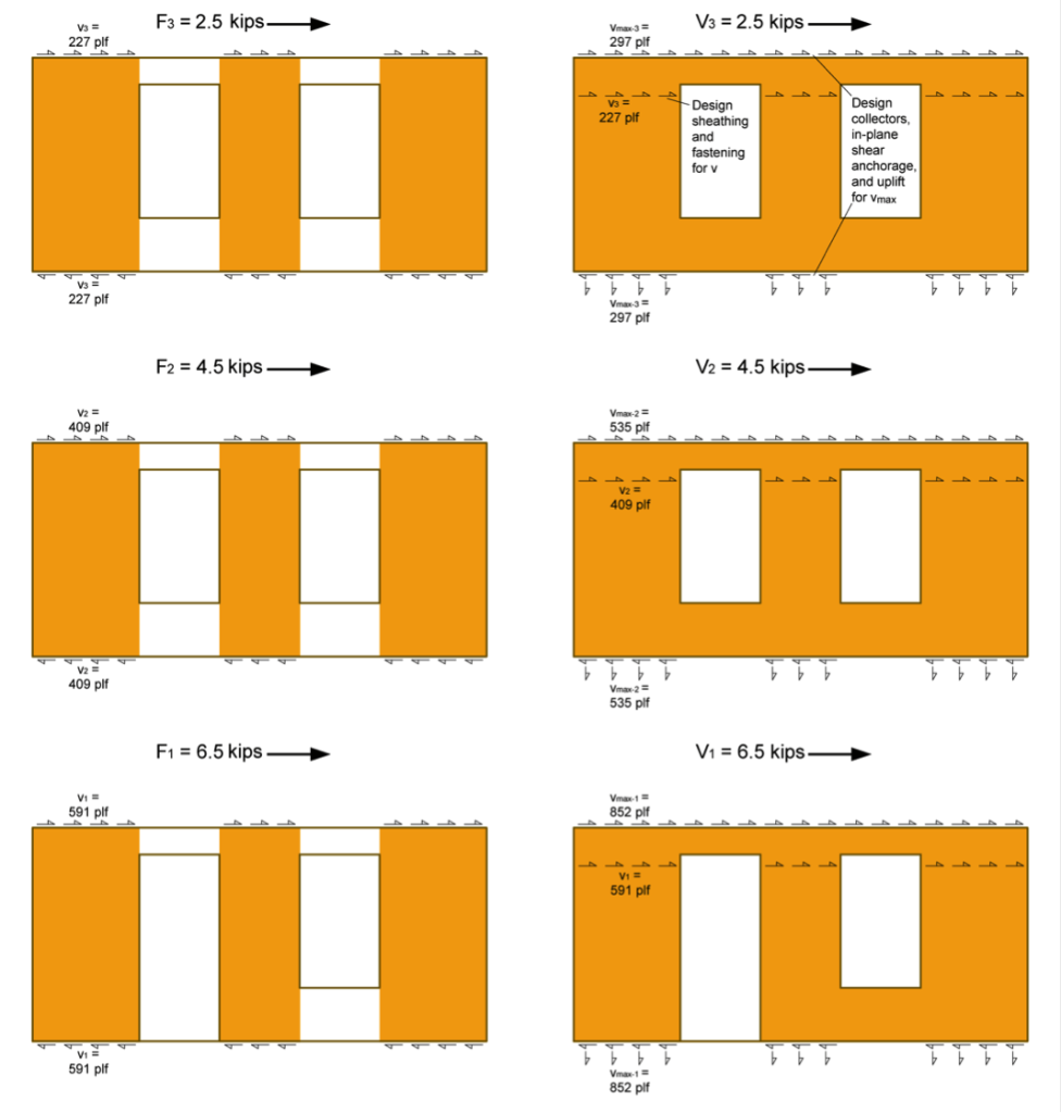
- Determine the Induced Unit Shear Force, v, for use with both shear wall types and the Maximum Induced Unit Shear Force, vmax, for the perforated shear wall collectors, shear transfer, and uniform uplift. Note the following:
- vmax requires the determination of the Shear Capacity Adjustment Factor, CO, for the perforated shear wall.
- The SDPWS provides two methods for determining CO, a tabulated value or a calculated value. This example uses the more precise calculated value.
- The perforated method requires the collectors be designed for vmax and the bottom plate to be anchored for a uniform uplift equal to vmax (as illustrated in the following figure).

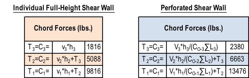
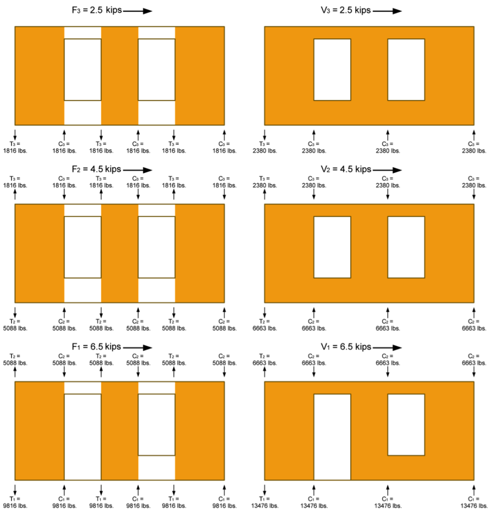
 3. Determine the Tension, T, and Compression, C, forces in the chords (assume no contribution from dead load for this example). Note the following:
- Reverse wind loading will require a mirror image of the T & C forces shown in the following figure.
- The tension forces, T, shown in the example reflect the cumulative tension forces as they are transferred down from post-to-post, as is typical with traditional holdowns. For continuous rod systems like ATS, the incremental tension forces (resulting from the unit shear, vor vmax, at that level only) must also be determined as shown in the shear wall specification table at the end of this example.

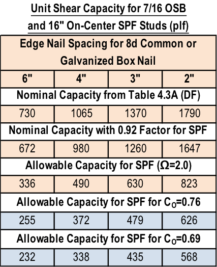
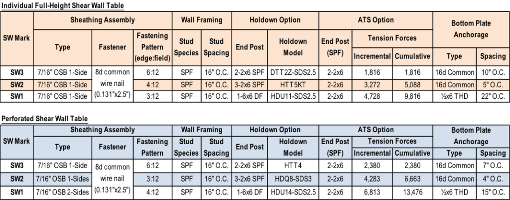
 4. Determine sheathing material and fastening pattern based on v calculated in Step 2. The table below is based on 7/16″ wood structural panel sheathing values in SDPWS Table 4.3A.
- Individual Full-Height Shear Wall:
i. v3=227 plf: Use 7/16 OSB with a 6:12 nailing pattern which has an allowable load of 336 plf
ii. v2=409 plf: Use 7/16 OSB with a 4:12 nailing pattern which has an allowable load of 490 plf
iii. v1=591 plf: Use 7/16 OSB with a 3:12 nailing pattern which has an allowable load of 630 plf
B. Perforated Shear Wall (apply CO factor to allowable shear capacity):
i. v3=227 plf: Use 7/16 OSB with a 6:12 nailing pattern which has an allowable load of 255 plf
ii. v2=409 plf: Use 7/16 OSB with a 3:12 nailing pattern which has an allowable load of 479 plf
iii. v1=591 plf: Use 7/16 OSB on both sides of the wall with a 4:12 nailing pattern which has an allowable load of 338*2=676 plf
5. Size the posts for compression. Simpson provides some useful tables in the back of the connector catalog with allowable tension and compression loads for a variety of sizes, heights, and species of posts.
6. Select holdowns for the tensions loads and verify post sizes are sufficient. For higher aspect ratio shear walls, the post size and holdown type may significantly reduce the moment arm between center of tension and center of compression, resulting in higher tension and compression forces.
The tables below show the shear wall specification for the walls in the example in a typical format. Note that they do not include some detailing that is required for items such as the uniform uplift force on the bottom plate of all perforated shear walls, or the perforated shear walls with OSB sheathing on both sides.
There are different ways to address the loads, so let us know if you would do anything differently in your designs.

Taking Wood-Framed Construction to New Heights
When I had more hair and less of it was gray, I worked on a project as an assistant engineer doing the calculations for a mixed-use building in San Jose, California. Final design consisted of four stories of wood framing over a concrete podium slab and another level of below-grade parking. At that time, my firm had designed many two- and three-story residential buildings, but common thinking was you switched to steel or concrete for taller structures because of perceived limitations in wood-framed construction.Continue Reading