Hydrogen Embrittlement in High-Strength Steels

The use of high-strength steels in anchors and fasteners is not unusual in the construction world. For example, high-strength threaded rods are often used to reduce the number of mild-steel rods that would be required to meet a design load for an adhesive anchor. High-strength steel is essential to the function of some fasteners, such as self-drilling and self-tapping screws.

However, for anchors and fasteners, there are limits to what can be accomplished by increasing steel strengths due to a phenomenon known as hydrogen embrittlement. Hydrogen embrittlement is well known by anchor and fastener manufacturers, but it is not widely known by structural engineers. The purpose of this blog post is to provide an overview of this important subject and some insight into one reason why steels used in construction anchors and fasteners have upper strength limits.

What is hydrogen embrittlement?

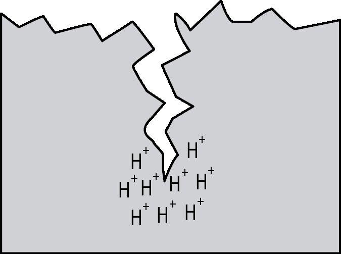
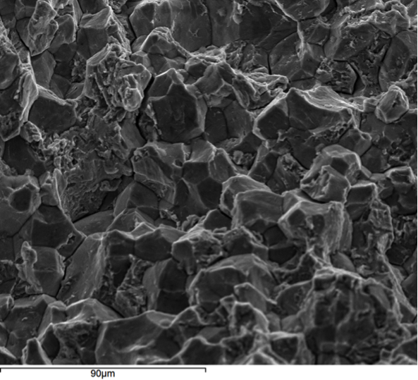
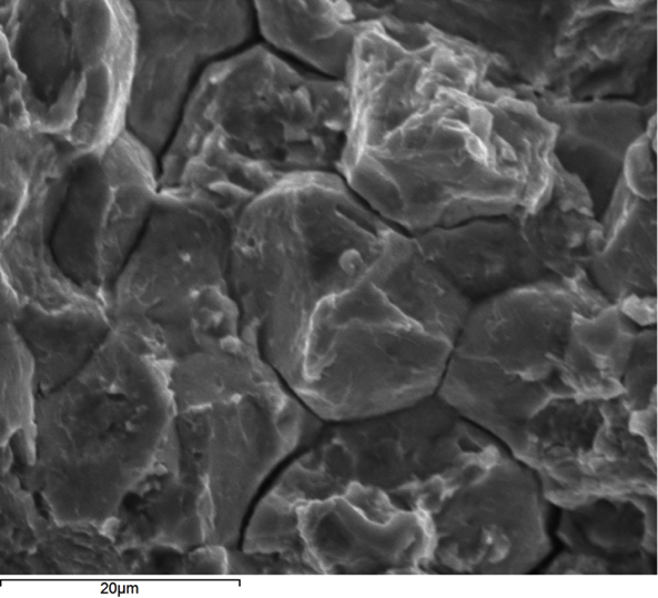
Hydrogen embrittlement is a significant permanent loss of strength that can occur in some steels when hydrogen atoms are present in the steel and stress is applied. Embrittlement occurs as hydrogen atoms migrate to the region of highest stress and cause microcracks. When a crack forms, the hydrogen then migrates to the tip of the crack (Figure 1) and causes continued crack growth until the effective fastener cross-section is so reduced that the remaining cross-section is overloaded and the fastener fails. Figures 2, 3 and 4 show a failure plane and coarse granular morphology and intergranular cracks (dark lines in Figures 3 and 4). These failures occur suddenly, without warning, after the fastener or rod has been loaded for a period of time.

Figure 1 – Conceptualized migration of hydrogen to the crack tip causing further cracking.
Fig. 2
Fig. 2
SE Blog 3
Fig. 3
SE Blog 4
Figure 2,3,4 – Scanning electron microscope images of intergranular cracking in a steel screw due to hydrogen embrittlement.

All three of the aforementioned conditions must be present for hydrogen embrittlement to occur:

  • A steel that is susceptible to hydrogen embrittlement
  • Atomic hydrogen (H+ ions, not H2 gas)
  • Stress, such as from tightening or applied loads

If an application involves these, then there is a possibility of hydrogen embrittlement and fastener failure. The possibility of and time to failure depend on the degree of each of these conditions. Therefore, the level of concern should depend on the degree to which the Designer expects all three of these conditions to be present in the application.


What steels are sensitive to hydrogen embrittlement?

A fastener’s susceptibility to hydrogen embrittlement increases with elevated tensile strength or hardness. It is generally accepted that good-quality fasteners with an actual (not specified) Rockwell C scale hardness of less than 38 (tensile strength of less than approximately 170,000 psi) are not ordinarily susceptible to hydrogen embrittlement. Fastener manufacturers often establish lower hardness limits as an extra margin of safety for variability that may occur in production.

When are hydrogen atoms (H+) present?

Hydrogen atoms can be introduced into a fastener from manufacturing or from the service environment.

Sources of hydrogen from manufacturing:

Hydrogen can be present in the steel-making process, but the amount present in good-quality steel is below the level that causes problems. The most common way that hydrogen is introduced during anchor and fastener manufacturing is from the cleaning and coating processes. These processes often utilize acids that produce hydrogen. Compounding this problem is that many popular coatings like zinc plating (ASTM B633) and hot-dip galvanizing (ASTM A153) create a barrier around the fastener that does not allow hydrogen to easily diffuse out of the fastener. Some coatings, like mechanical galvanizing (ASTM B695), do have sufficient porosity that hydrogen can diffuse through the coating at room temperature.

Manufacturers most commonly manage internal hydrogen sources by minimizing cleaning time and by baking plated fasteners after coating for a number of hours to help diffuse hydrogen through the coating and out of the fastener. In some cases, mechanical cleaning and alkaline cleaning are used to prevent hydrogen from being introduced.

In cases where internal hydrogen is not properly managed in the manufacturing process, failure usually occurs quickly, within 48 hours of fastener installation.

External sources of hydrogen:

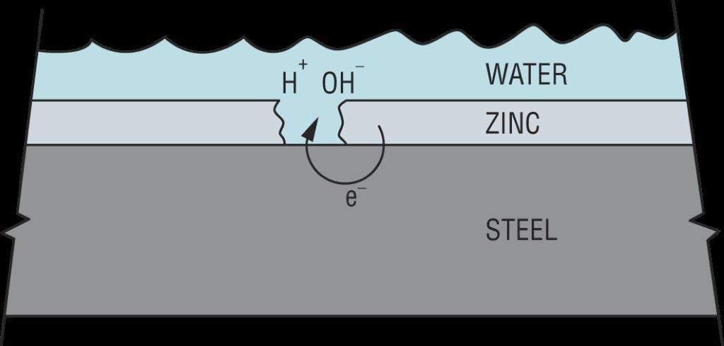
Hydrogen can also be introduced from the service environment. Zinc coatings galvanically protect steel from corrosion in damp or wet service environments. However, this process results in an electric current being passed through the water (H2O) to produce hydrogen (H+) and hydroxide (OH) ions as shown in Figure 5. Since this process requires corrosion to generate the hydrogen, failures from externally generated hydrogen usually take much longer to occur than when internal hydrogen is the cause. Steel failure from externally generated hydrogen can take anywhere from weeks to years.

Figure 5 – Production of hydrogen (H+) from the galvanic protection of steel by a zinc coating

How much stress is too much stress?

Fortunately, for products that require very high-strength steels, hydrogen embrittlement risk diminishes, even for sensitive steels, as applied loads are reduced. For such products there are a number of complex tests that fastener manufacturers utilize in development and quality control to verify that the risk of hydrogen embrittlement is controlled for the intended application at the rated loads.

Closing thoughts

As illustrated in the discussion above, hydrogen embrittlement can be a serious concern for high-strength anchors and fasteners. A Designer should exercise great care to guard against the sudden brittle steel failure that this phenomenon can produce. There are a number of good practices to follow in this regard:

  • Do not utilize exotic high-strength steels with actual tensile strengths greater than 170,000 psi (Rockwell C-scale hardness of 38) without carefully considering hydrogen embrittlement risk. Note that actual tensile strength may be higher than specified tensile strengths.
  • Ensure that quality sources of high-strength fasteners are specified. High-quality manufacturers have design and manufacturing practices in place to guard against hydrogen embrittlement.
  • Use discretion in selecting very high-strength fasteners for corrosive applications since these conditions often produce hydrogen through the galvanic process.

Understanding and Meeting the ACI 318 – 11 App. D Ductility Requirements – A Design Example

If you’re one of the many engineers still confused by the ACI 318 – 11 Appendix D design provisions, this blog will help explain what’s required to achieve a ductile performing anchorage. Most building codes currently reference ACI 318 – 11 Appendix D as the required provision for designing a wide variety of anchor types that include expansion, undercut, adhesive and cast-in-place anchors in concrete base materials. This blog post will focus on section D.3.3.4.3(a) for an anchor located in a high seismic region. We’ll go over what these requirements are with a simple design example.

Ductility is a benefit in seismic design. A ductile anchor system is one that exhibits a meaningful degree of deformation before failure occurs. However, ductility is distinct from an equally important dimension called strength. Add strength, and a ductile steel element like the one shown in Figure 1 can now exhibit toughness. During a serious earthquake, a structural system with appreciable toughness (i.e., one that possesses both strength and ductility in sufficient degree) can be expected to absorb a tremendous amount of energy as the material plastically deforms and increases the likelihood that an outright failure won’t occur. Any visible deformations could help determine if repair is necessary.

Figure 1 – ½" mild steel threaded rod tensilely loaded to failure (starting stretch length = 8d)
Figure 1 – ½” mild steel threaded rod tensilely loaded to failure (starting stretch length = 8d)

Let’s start off with a simple example that will cover the essential requirements for achieving ductility and applies to any type of structural anchor used in concrete. We’ll arbitrarily choose a post-installed adhesive anchor. This type of anchor is very common in concrete construction and is used for making structural and nonstructural connections that include anchorage of sill plates and holdowns for shear walls, equipment, racks, architectural/mechanical/electrical components and, very frequently, rebar dowels for making section enlargements. We’ll assume the anchor is limited to resisting earthquake loading in tension only and is in seismic design category C – F. Section D.3.3.4.2 requires that if the strength-level earthquake force exceeds 20% of the total factored load, that the anchor be designed in accordance with section D.3.3.4.3 and D.3.3.4.4. We will focus on achieving the ductility option, (a), of D.3.3.4.3.

To understand anchor ductility we need to first identify the possible failure modes of an anchor. Figure 2 shows the three types of failure modes we can expect for an adhesive anchor located away from a free edge. These three failure modes generically apply to virtually any type of anchor (expansion, screw, cast-in-place or undercut). Breakout (Nb) and pullout (Na) are not considered ductile failure modes. Breakout failure (Nb) can occur very suddenly and behaves mostly linear elastic and consequently absorbs a relatively small amount of energy. After pullout failure (Na) has been initiated, the load/displacement behavior of the anchor can be unpredictable, and furthermore, no reliable mechanism exists for plastic deformation to take place. So we’re left with steel (Nsa). To achieve ductility, not only does the steel need to be made of a ductile material but the steel must govern out of the three failure modes. Additionally, the anchor system must be designed so that steel failure governs by a comfortable margin. Breakout and pullout can never control while the steel yields and plastically deforms. This is what is meant by meeting the ductility requirements of Appendix D.

Figure 2 –Three possible failure modes for an adhesive anchor loaded in tension
Figure 2 – Three possible failure modes for an adhesive anchor loaded in tension

Getting back to our design example, we have a single post-installed 5/8” diameter ASTM F1554 Gr. 36 threaded rod that’s embedded 12” deep, in a dry hole, in a concrete element that has a compressive strength of 2,500 psi. The concrete is 18” thick and we assume that the edge distance is large enough to be irrelevant. For this size anchor, the published characteristic bond strength is 743 psi. Anchor software calculations will produce the following information:

ductility4

The governing design strength is compared to a demand or load combination that’s defined elsewhere in the code.

Here’s the question: Before proceeding with the remainder of this blog, judging by the design strength values shown above, should we consider this anchorage ductile? Your intuition might tell you that it’s not ductile. Why? Pullout clearly governs (i.e., steel does not). So it might come as a surprise to learn that this adhesive anchor actually is ductile!

To understand why, we need to look at the nominal strength (not the design strength) of the different anchor failure modes. But first let’s examine the equations used to determine the design strength values above:

ductility5

The above values incorporate the notation φ (“phi”) and a mandatory 0.75 reduction factor for nonductile failure modes (Ncb ,Na) for applications located in high seismic areas (seismic design category C–F). The φ factor is defined in section D.4. However, manufacturers will list factors specific to their adhesive based on anchor testing. The mandatory 0.75 reduction comes from section D.3.3.4.4 and is meant to account for any reduction associated with concrete damage during earthquake loading. The important thing to remember is that the nominal strength provides a better representation of the relative capacity of the different failure modes. Remove these reduction factors and we get the following:

ductility6

Now steel governs since it has the lowest strength. But we’re not done yet. Section D.3.3.4.3.(a).1 of Appendix D requires that the expected steel strength be used in design when checking for ductility. This is done by increasing the specified steel strength by 20%. This is to account for the fact that F1554 Gr. 36 threaded rod, for example, will probably have an ultimate tensile strength greater than the specified 58,000 psi. (Interestingly, the ultimate strength of the ½” threaded rod tested in Figure 1 is roughly 74 ksi, which is about 27% greater than 58,000 psi.) With this in mind, the next step would be to additionally meet section D.3.3.4.3.(a).2 such that the following is met:

ductility7

By increasing the steel strength by 20%, the nominal strength of the nonductile failure modes (Ncb ,Na) must be at least that much greater to help ensure that a ductile anchor system can be achieved. The values to compare finally become:


ductility8Now steel governs, but one more thing is required. As shown in Figure 3, Section D.3.3.4.3.(a).3 of Appendix D also requires that the rod be made of ductile steel and have a stretch length of at least eight times the insert diameter (8d). Appendix D defines a ductile steel element as exhibiting an elongation of at least 14% and a reduction in area of at least 30%. ASTM F1554 meets this requirement for all three grades of steel (Grade 36, 55 and 105) with the exception of Grade 55 for anchor nominal sizes greater than 2”. Research has shown that a sufficient stretch length helps ensure that an anchor can experience significant yielding and plastic deformation during tensile loading. The threaded rod shown in Figure 1 was tested using a stretch length of 4” (8d). Lastly, section D.3.3.4.3.(a).4 requires that the anchor be engineered to protect against buckling.

Figure 3 – Stretch length

Appendix D doesn’t require that an anchor system behave ductilely. Three additional options exist for Designers in section D3.3.4.3. Option (b) allows for the design of an alternate failure mechanism that behaves ductilely. Designing a base plate (or support) that plastically hinges to exhibit ductile performance is one example. Option (c) involves a case where there’s a limit to how much load can be delivered to the anchor. Although option (c) under D.3.3.4.3 falls under the tensile loading section of Appendix D, the best example would apply to anchorage used to secure a wood sill plate or cold-formed steel track. We know from experiments that the wood crushes or the steel yields and locally buckles at a force less than the capacity of the concrete anchorage. Clearly energy is absorbed in the process. The most commonly used option is (d), which amplifies the earthquake load by Ωo. Ωo can be found in ASCE 7 – 10 for both structural and nonstructural components. The value of Ωo is typically taken to be equal to 2.5 (2.0 for storage racks) and is intended to make the anchor system behave linear elastically for the expected design-level earthquake demand.

These same options exist for shear loading cases. However, achieving system ductility through anchor steel is no longer an option for shear loading according to ACI 318 – 11, because the material probably won’t deform appreciably enough to be considered ductile.

While factors such as edge-distance and embedment-depth restrictions make achieving ductility difficult for post-installed anchors, it should come as some consolation that in many cases the Designer can achieve ductile performance for cast-in-place anchors loaded in tension through creative detailing of reinforcing steel (section D.5.2.9) to eliminate breakout as a possible failure mode. This has been explored in some detail in two previous Simpson Strong-Tie blogs titled “Anchor Reinforcement for Concrete Podium Slabs” and “Steel Strong Wall Footings Just Got a Little Slimmer.”