

The world has seen many increasingly catastrophic natural disasters in the past decade, including Hurricane Katrina (Category 3) striking New Orleans in 2005, 2010’s 7.0 magnitude Haiti and 8.8 magnitude Chili earthquakes, the 9.0 magnitude Japan earthquake along with the Christchurch earthquake (6.3 magnitude) in 2011, the tornado outbreak in 2011 which included an EF4 striking Tuscaloosa, AL and a multiple-vortex EF5 striking Joplin, MO. We also saw Category 2 Hurricane Sandy, the largest Atlantic hurricane on record in 2012 and the EF5 tornado striking Moore, Oklahoma in 2013.
Author: Jeff Ellis
I’m a licensed Civil and Structural Engineer in California and several other U.S. states and have been a practicing engineer since 1991. Prior to coming to Simpson Strong-Tie in 2000, I was a design engineer for small and large commercial, institutional, residential, and forensic projects designing with wood, cold-formed steel, structural steel, masonry, and concrete. I began working at Simpson Strong-Tie as a southwest regional office branch engineer, then served as the branch engineering manager, and then managed our codes and compliance efforts. Currently, I’m the Director of Strengthening and leading our North American concrete and masonry strengthening efforts. I’ve written several articles and design guides and have served on several industry technical groups over the years including as SEAOSC board director and president, SEAOC Secretary, CALBO Structural Safety Committee member, ICC-ES Board of Managers, AISI COFS Lateral Design Subcommittee chair, president of CFSEI, and I’m currently the board chair for the U.S. Resiliency Council. It’s a pleasure to work with so many talented, dedicated, and passionate folks here at Simpson Strong-Tie and the industry striving to help create safer, stronger structures.
Midrise of Steel

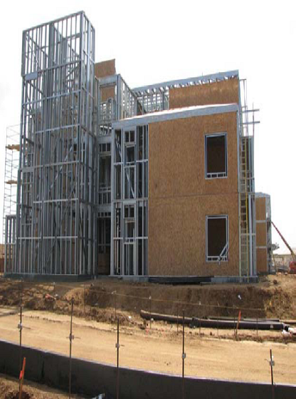
The number of midrise structures constructed using light-frame cold-formed steel (CFS) certainly seems to be increasing each year. As with any material, there are benefits and challenges, especially in areas of moderate to high seismic risk. This post will discuss these as well as potential solutions.
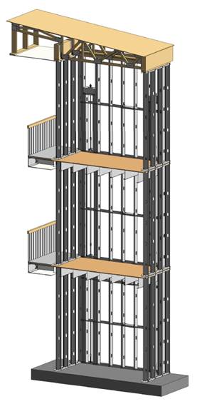
Light-frame CFS midrise construction often uses ledger floor framing primarily to facilitate the load transfer detailing at the floor, tension anchorage (tie-downs or hold-downs) and compression chord studs or posts designed to resist the amplified seismic overturning loads. CFS framing is typically thin and singly symmetric.

Amplified Seismic Load
The AISI Lateral Design standard (AISI S213-07/S1-09) Section C5.1.2 requires that the nominal strength of uplift (tension) anchorage and the compression chord studs for shear walls resist the lesser of (1) the amplified seismic load or (2) the maximum load the system can deliver when the response modification coefficient, R, greater than 3. The amplified seismic load is defined as the load determined using the ASCE 7 seismic load combinations with the overstrength factor, Wo, which may be taken as 2.5 for CFS framed shear wall systems with flexible diaphragms.
Typically, the maximum the system can deliver to the uplift anchorage or chord studs is taken as the forces determined using the nominal shear strength of the shear wall assembly tabulated in the seismic shear wall table in S213 multiplied by 1.3. The S213 commentary accounts for the tabulated loads being based on Sequential Phased Displacement (SPD) rather than CUREE cyclic protocol and the degraded backbone curve. See the Structure magazine article that discusses the design of CFS framed lateral force-resisting systems.
Continuous Rod Tie-Down Systems
Light-framed CFS over three stories often use continuous rod tie-down systems rather than cold-formed steel hold-downs to resist shear wall overturning forces as they offer increased load capacity. Neglecting the dead load contribution, the amplified seismic load requirement for CFS shear walls using an R greater than 3 results in an 80% increase in the load used to size the continuous rod tie-down system compared to design level loads. For shear walls using an R greater than 3, it is important to note on the design drawings whether the uplift loads shown are ASD, LRFD, amplified ASD or amplified LRFD so the appropriate tie-down system may be designed.
Continuous rod tie-down systems are designed not only for strength, but also checked to ensure they do not deflect too much to cause the top of shear wall drift to exceed the code limit or to exceed the 0.20” vertical story deflection limit required by some jurisdictions and ICC-ES AC316. Take-up devices are used in CFS framed structures to take-up construction and settlement gaps that may occur. AISI S200 Section C3.4.4 states that a gap of up to 1/8” might occur between the end of wall framing and the track. The vertical elongation of the continuous rod tie-down system includes rod elongation (PL/AE) and the take-up device deflection due to the seating increment and the deflection under load.
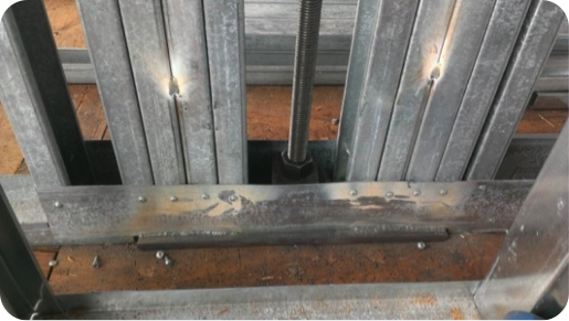
In addition, coordination is important in using continuous rod tie-down systems in CFS structures because the walls are often prefabricated offsite. An example is the consideration of the appropriate detail for the steel bearing plate installed at the floor sheathing in the story above to resist the uplift (tension) force from the story below.
One possible detail is to install the bearing plate in the bottom CFS track under all the CFS chord studs, but it’s important to ensure the bottom track flanges are deep enough to screw them to the stud flanges as the bearing plate can have a thickness of 1 ½” or more and typical tracks use 1 ¼” flanges. It is also important to ensure that the bearing plate width fits in the track. Another possible detail is to install the bearing plate under the CFS track under all the CFS chord studs. However, then it must be cut into the floor sheathing and may cause the bottom track to be raised at the bearing plate. For this detail, the floor shear transfer must be detailed through the ledger into the CFS framing.
Concrete Tension Anchorage
The concrete tension anchorage is designed according to ACI 318 Appendix D using the continuous steel rod material and size in accordance with S213 to have the nominal strength to resist the lesser of the amplified seismic force or the maximum load the system can deliver. ACI 318-11 Section D.3.3.4.3 offers four force limits for design of concrete tension anchorage design in Seismic Design Category C through F:
(1) The concrete nominal tension anchorage strength shall be greater than 1.2 times the ductile steel rod nominal tension anchorage strength
(2) The anchorage design strength shall be greater than the maximum tension force that can be delivered by a yielding attachment;
(3) The anchorage design strength shall be greater than the maximum tension force that can be delivered by a non-yielding attachment; and
(4) The anchorage design strength shall be greater than the amplified seismic force.
Typically either option (1) or (4) is used where (1) would lead to less concrete required than (4) if the bolt is efficiently sized while (4) would be required for such conditions as a vertical irregularity. See the concrete anchorage and podium anchorage SE Blog posts for more details.

CFS Wall Stud Bracing
CFS studs are typically thin and singly symmetric and thus require bracing. AISI S211 (Wall Stud Design Standard) permits two types of bracing design that cannot be combined; sheathing based or steel based. There are limits on the stud axial strength when using sheathing braced design. It’s important to identify on the drawings that the sheathing braces the studs and another load combination must be used for the stud design.
2012 IBC Section 2211.4 requires stud bracing to be designed using either AISI S100 (North American Specification) or S211 (Wall Stud Design Standard). S100-07 Section D3.3 required nominal brace strength is to be 1% of the stud’s nominal compressive axial strength, but S100-12 Section D3.3 changes this to the required brace strength is to be 1% of the stud’s required compressive axial strength (demand load). In addition, D3.3 requires a certain stiffness for each brace. AISI S211 required brace strength is to be 2% of each stud’s required compressive axial strength for axially loaded studs and, for combined bending and axial loads, be designed for the combined brace force per S100 Section D3.2.2 and 2% of the stud’s required compressive axial strength.
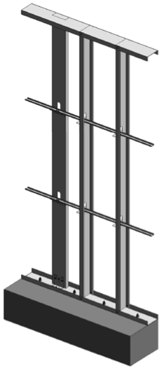
There are two primary types of steel stud bracing systems: bridging and strap bracing. U-channel bridging extends through the stud punchouts and is attached to the stud with a clip, of which there are various solutions such as this post on Wall Stud Bridging. Bridging bracing requires coordination with the building elements in the stud bay. It installs on one side of the wall, and does not bump out the wall sheathing. It also requires periodic anchorage to distribute the cumulative bracing loads to the structure for axially loaded studs often using strongback studs and does not require periodic anchorage for laterally loaded studs since the system is in equilibrium as the torsion in the stud is resisted by the U-channel bending.
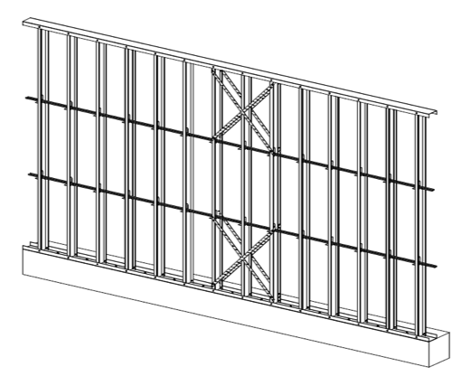
Flat strap bracing is installed on either side of the wall and at locations other than the stud punchout. It bumps out the sheathing and requires periodic anchorage to distribute the cumulative bracing loads to the structure for axially and laterally loaded studs.
![]()

![]()
Light-frame cold-formed steel construction has been used successfully for many projects, but there are challenges that must be addressed to ensure code compliance and desired performance. Some beneficial resources for designing CFS structures are the SEAOC 2012 IBC Structural/Seismic Design Manual Volumes 1 and 2 and the Cold-Formed Steel Engineers Institute’s (CFSEI) website where you can find technical notes and design guides.
What have been some of your observations or challenges in designing cold-formed steel midrise structures?
Wings or No Wings?
While the title of this blog post might remind you of the tasty turkey dinner you enjoyed on Thanksgiving, it’s actually a question regarding a shear wall component’s effect on performance. What type of fastener do you use to attach wood structural panel sheathing to cold-formed steel (CFS) framing, and what is the effect on a shear wall assembly?
Structural sheathing is most commonly attached to CFS framing with self-piercing or self-drilling tapping screws, power driven pins, and adhesives.
The AISI North American Standard for Cold-Formed Steel Framing – Lateral Design standard (S213) specifies using either #8 or #10 self-tapping screws (depending on the assembly) that comply with ASTM C1513, and have a minimum head diameter of 0.285” or 0.333”, respectively.
It’s worth noting that you cannot verify ASTM C1513 compliance by simple inspection. While screw dimensions are easy to measure, other features such as hardness, ductility, torsional strength, drill drive, and thread tapping cannot be evaluated in the field or by visual inspection. It’s prudent that a Designer and jurisdiction expect a screw manufacturer to validate its product’s compliance with ASTM C1513. This can be done through test reports by an accredited test lab and evaluation data, or by an evaluation report published by an ANSI-accredited product certification entity such as ICC-ES or IAPMO UES.Continue Reading
Call for Papers: 22nd International Conference on CFS Structures
The Wei-Wen Yu Center for Cold-Formed Steel Structures has issued a Call for Papers for the 22nd International Conference on Cold-Formed Steel (CFS) Structures, to be held Nov. 5-6 in St. Louis, MO. The goal of the conference is to enable sharing of state-of-the-art information pertaining to CFS design.
Both engineering researchers and practitioners have provided valuable contributions to the conference. Past proceedings are available online.
 Researchers and practitioners are encouraged to submit abstracts for consideration by the conference steering committee. Application-oriented topics highlighting innovations in CFS applications are strongly encouraged. The deadline is Dec. 31. Abstracts may be submitted by e-mail to ccfss@mst.edu.
What are your thoughts? Visit the blog and leave a comment!

2013 Buildings At Risk Summit Focused on Individual and Community Safety, Resiliency
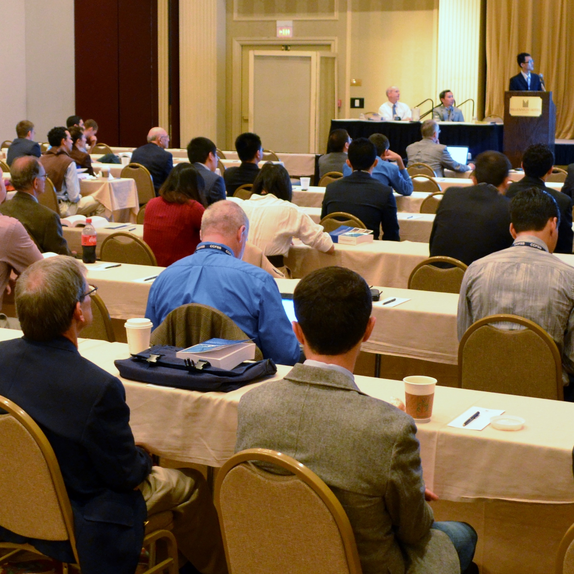
The Structural Engineers Association of Northern and Southern California hosted the third annual Buildings At Risk ǀ Earthquake Loss Reduction Summit in Los Angeles on October 8 and in San Francisco on October 15. Robust panel presentations and discussions presented by professionals from diverse yet complimentary fields targeted a mixed audience of building owners, architects, engineers, government officials, insurance representatives, and financial industry representatives.Continue Reading
23rd Short Course on CFS Structures: October 15-17 in St. Louis
Simpson Strong-Tie is sponsoring the 23rd Short Course on Cold-Formed Steel Structures hosted by the Wei-Wen Yu Center for Cold-Formed Steel Structures (CCFSS). The course will be held on October 15-17, 2013 at the Drury Plaza Hotel at the Arch in St. Louis, MO.
This course is for engineers who have limited or no experience designing with cold-formed steel (CFS), as well as those with experience who would like to expand their knowledge. Lectures will be given by industry-recognized experts Roger LaBoube, Ph.D, P.E., and Sutton Stephens, Ph.D, P.E., S.E. The course is based on the 2007 and 2012 AISI North American Specification for the Design of Cold-Formed Steel Structural Members with the 2010 Supplement (AISI S100-07/S2-10 and S100-12) and will reference the Cold-Formed Steel Design (4th Edition) text.
Topics include design of wall studs, floor joists, purlins, girts, decks and panels. For more information and to register, visit the CCFSS website.
– Jeff
3, 2, 1. . .Countdown to Earthquake!
This week, I’d like to introduce Jeff Ellis as a guest blogger for the Structural Engineering Blog. Jeff is the Manager of Codes, Standards and Special Projects for Simpson Strong-Tie. Jeff will be posting occasionally on topics that are relevant to our work, especially related to cold-formed steel (CFS) construction.
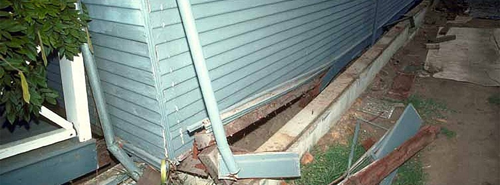
When was the last time you knew an earthquake was coming and witnessed its effects on a building without feeling any shaking yourself? Since the mid- to late ‘90’s, several uni-axial and tri-axial shake tables have been built and used to better understand whole building performance under actual earthquake ground motion in order to improve code requirements and, in some cases, develop performance-based design methods.Continue Reading