Introducing the Joist Hanger Selector Web App

Designing buildings and dealing with construction has always been a satisfying career for me. It is challenging to design a complete structural system, coordinate with the other consultants and create a clear set of construction documents for the contractor. Throughout my career, I’ve occasionally had a few panicked “Uh oh!” moments. I hope I’m not alone in admitting those happen. These typically occur far away from work when something prompts me to think about a project. I might see concrete being placed, then question whether I remembered to change the reinforcing callout on a mat slab I had just designed. I can’t stop thinking about it until I get back in the office to check.

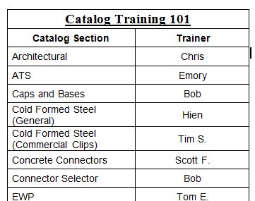
I had an “Uh oh!” moment a few days after I started work at Simpson Strong-Tie. We have a training plan I call Catalog 101 where new engineers meet with each engineer who is an expert for a given product line. After I had met with our experts on holdowns, concrete anchors and engineered wood products, it was on to top-flange hangers (and my “Uh oh!” moment).

Catalog 101
We really do call it Catalog 101

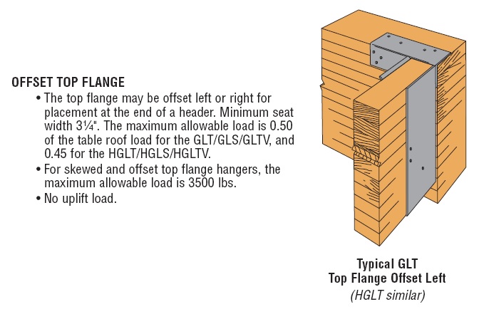
After learning a lot of things I didn’t know about hangers, we moved on to available options for some of our top-flange hangers – sloped, skewed, sloped and skewed, sloped top-flange, and offset top-flange. I learned that some hanger options get full load, some have small reductions and others large reductions. For example, the GLT with an offset top-flange gets 50% of the table load.

GLT/HGLT hanger options section of Wood Construction Connectors Catalog, C-2013

“Uh oh!”

I had recently designed a project and specified a bunch of GLT hangers with offset top-flanges. I hadn’t noticed there was a reduction for this modification; I just thought it was really cool that Simpson Strong-Tie had a hanger that worked at the end of a beam. Minor panic set in until I could check my calculations. Fortunately, the beams at the framing conditions that required offset hangers had half the load of the typical beams, so the hanger was okay even with the load reduction.

Hanger Option Matrix from Wood Construction Connectors Catalog, C-2013

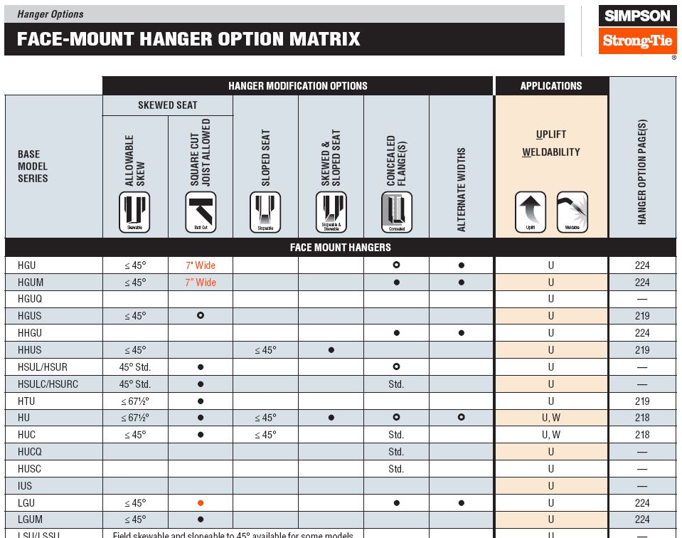
The Wood Construction Connectors Catalog has a Hanger Options Matrix that makes it relatively simple to see which options – sloped, skewed, concealed, welded – are available for each hanger. The pages following the options matrix have more detailed information about size restrictions and load reductions associated with each option. It can be somewhat tedious to sift through all of the options and apply the reduction factors, so I always recommend using the Simpson Strong-Tie Connector Selector® software to do the work for you.

Connector Selector
Connector Selector

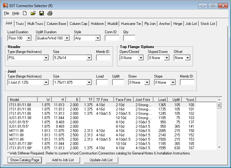
Connector Selector software allows you to input you geometry and loads and returns a list of connectors that meet those requirements, including any reductions due to modifications. Connector Selector is a desktop application, which needs to be downloaded and installed on your PC. Engineers have indicated they like the functionality of Connector Selector, but wished the input was more intuitive and preferred it as a web application.

Joist Hanger Selector web app

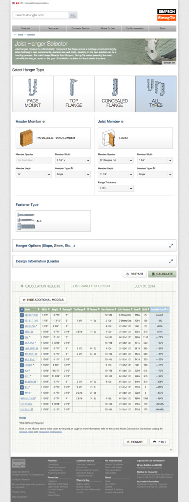
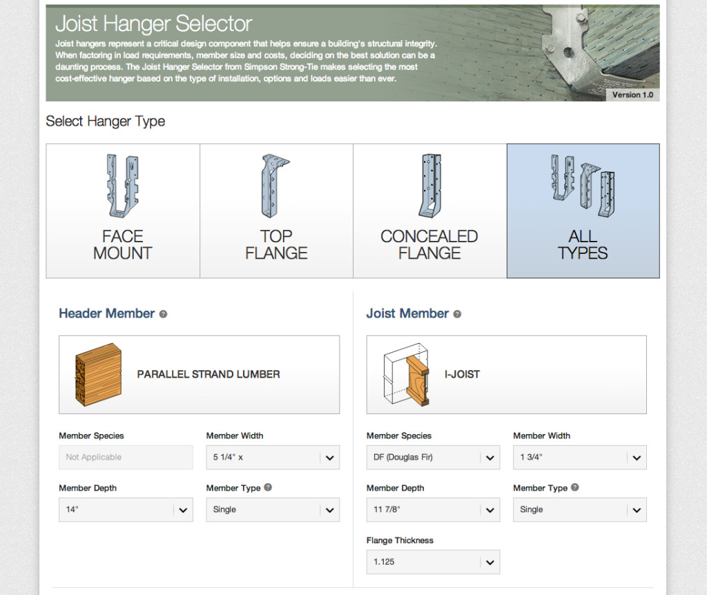
I’m happy to say we listen, and the new Simpson Strong-Tie Joist Hanger Selector web app is available now. The easy-to-use interface enables users to quickly select the connection details and print out results. You can access the app from any web browser without having to download or install special software. The allowable loads are automatically calculated to reflect reductions associated with modifications – no more “Uh oh!” moments for me (at least with hangers).

Joist Hanger Selector App
The joist hanger selector app makes it easy to pick the right hanger.

Give the new Joist Hanger Selector web app a try and let us know what you think. We always appreciate your feedback!

Resources and Continuing Education for Structural Engineers

I’ll admit that I’m biased, but structural engineers have the best job in the world. We’re needed to create safe sound structures while factoring in the effects of environmental forces using a combination of physics and experience. It takes a really well rounded individual to do all of that.

In my opinion, the key to being a well rounded professional is to never stop learning or seeking out new resources in your industry. I thought I’d share with you some resources that may be helpful to you as a structural engineer, from my own experience:

Continuing Education Webinars

Attending webinars online is a great way to get Continuing Education credits you need. Webinars enable you to stay sharp on topics that are continually changing and that you may need to adapt to in our industry.

Some of the resources engineers at Simpson Strong-Tie go to for webinars and CECs include:

ACI – American Concrete Institute

AISC – American Institute of Steel Construction

ASCE – American Society of Civil Engineers

AWC – American Wood Council

CFSEI – Cold-Formed Steel Engineers Institute

NCSEA –  National Council of Structural Engineers Association

SEAOSC – Structural Engineers Association of Southern California  

Engineering Associations

Training
Structural engineering associations often offer in person trainings.


Keeping in touch with fellow structural engineers means that you can talk shop and get some great advice about issues you face on the job. Some associations you can look into:

SEAINT- Structural Engineers Association – International 

NCSEA- National Council of Structural Engineers Associations 

SEAOC- Structural Engineers Association of California

SEAOSC- Structural Engineers Association of Southern California 

SEAOCC- Structural Engineers Association of Central California 

SEAOSD- Structural Engineers Association of San Diego

SEAU- Structural Engineers Association of Utah

ASCE- American Society Of Civil Engineers

ACI- American Concrete Institute

AISC- American Institute of Steel Construction

PCA- Portland Cement Association

PCI- Precast/Prestressed Concrete Institute

CRSI- Concrete Reinforcing Steel Institute

AISI- American Iron and Steel Institute

Simpson Strong-Tie also offers great software resources for structural engineers and other building industry professionals. What resources do you recommend? Let us know in the comments below.

2014 Updates to Technical Report 12

This January I wrote a blog post, Spanning the Gap, which discussed two methods for establishing allowable loads for fasteners installed through  gypsum board – testing or calculations using American Wood Council’s Technical Report 12. AWC recently published a new version of TR12 and this week’s guest blogger, Lori Koch, Project engineer with AWC, authored this post to explain some of the new features of TR12.

Lori Koch graduated from Penn State University with a BS in Civil Engineering, and from Clemson University with an MS in Civil Engineering. After graduating from Clemson, Lori worked as a forensic structural engineer doing field inspections, job site monitoring for compliance with project specifications and structural analysis on existing structures. She then enrolled at Virginia Tech pursuing a Master of Forestry degree in the Department of Wood Science and Forest Products (now called the Department of Sustainable Biomaterials). Her research at Virginia Tech involved connections for fall-protection harnesses for residential roofers and construction workers. After graduation in 2012, Lori started working with the American Wood Council as a Project Engineer. Her work at the AWC ranges from assisting in codes and standards development, answering HelpDesk inquiries, outreach and educational opportunities and just about anything that can help promote the use of wood in safe and sustainable buildings.

The American Wood Council’s Technical Report 12 – General Dowel Equations for Calculating Lateral Connection Values (TR12) was recently updated. TR12 provides background and derivation of the mechanics-based approach for calculating lateral connection capacity used in the National Design Specification® (NDS®) for Wood Construction for connections using dowel-type fasteners including bolts, lag screws, wood screws, nails, spikes, and drift pins. It also provides additional flexibility and broader applicability to the NDS provisions, including design provisions for connections with gaps.  The 2014 version of TR12 provides new information on design of wood members attached to hollow members and design of driven-fasteners with tapered tips.

The previous version of TR12 presented mechanics-based derivations of lateral yield equations for solid members joined with a dowel-type fastener (Figure 1). Following the same approach, yield equations were derived for connections between solid members and members with hollow cross sections (Figure 2). These new equations are presented in tabular form for connections with a solid main member and hollow side member(s) and connections with a hollow main member and solid side member(s). Derivations of these yield equations are also presented in the report.

Figure 1. Yield Modes for members of solid cross section.
Figure 2. Yield Modes for members of solid and hollow cross section.

The 2012 NDS section 11.3.5.2 adopted new provisions for driven fasteners with tapered tips. For a driven fastener where the penetration length includes the length of the tapered tip, the dowel bearing length is taken as the length of penetration minus one half of the length of the tip. TR12 provides derivation of yield equations that account for the full penetration length, including the reduced bearing capacity at the tip. Design values using these yield equations are then compared against the simplified approach in the 2012 NDS Results of that comparison are contained in a new example included in TR12, and show excellent agreement between the simplified and exact models.

There are many applications where TR12 can be used by engineers to expand upon the NDS connection provisions. Previous versions of TR12 have provided designers with the ability to design connections with a gap between the members. The new provisions in TR12 can be used to calculate the connection capacity of a hollow steel tube connected to solid lumber, where the tube can be either the main member or side member(s).

The recent updates to TR12 will provide increased flexibility for designers while providing additional background information on the derivation of the connection equations. The report is available for free download on the AWC’s webpage at http://www.awc.org/publications/TR/index.php.

What are your thoughts on these updates to TR12? Let us know in the comments below.

Wide Flange Beams in Light Frame Construction

How did that beam get so big? This is what I had to ask myself when I finished sizing and detailing a steel beam that was supposed to fit within the floor joist depth for a flush ceiling. We were removing an unreinforced masonry bearing wall and installing a new wide flange beam to support the existing floor joists as part of a seismic retrofit and remodel. Since the floor joists spliced over the existing bearing wall, it would have been much easier to simply install a new beam below the joists.

Beam below joists
Beam below joists

The architect did not want the beam installed below the framing, as it would protrude too much. Steel design offers multiple wide flange sections that will work for a given loading. For this particular design, I could use a W24x55, a W16x67 or a W14x90. Each has about the same strength (section modulus, Sxx) and stiffness (moment of inertia, Ixx). Without constraints, you would select the lightest section that works. Space limitations that require a shallower beam result in increased beam weight (and cost).

Beam flush with ceiling
Framing hung off beam

I proposed two solutions for installing the beam in the floor space and hanging the joists off a nailer. One option allowed the steel beam to extend below the floor joists, while the other used a heavier, shallower beam to fit within the space. The owner wanted a flat ceiling and did not mind the added cost for the beam, which weighed about 60% more than the optimum beam size.

Regardless of space constraints for the design of a steel beam, structural engineers need to specify an appropriate hanger for connecting to the steel beam. Simpson Strong-Tie has many suitable top flange hangers. Most common are hangers that are attached to a wood nailer. Many top flange hangers may also be welded to the beam. Not every nailer solution is rated for uplift, so choose a hanger that meets your requirements. Uplift for welded hangers is addressed in a Simpson Strong-Tie® technical bulletin, T-WELDUPLFT.

Hanger Install
Hanger Install
Nailer Table
Nailer Table

Installers may also wish to connect the hangers using powder-actuated fasteners in lieu of welding. Allowable loads for several of our top flange hangers are addressed in an engineering letter, ITS, MIT, LBV, and BA Hangers Installed on a Steel Header with Powder-Actuated Fasteners.

Of course, as with all of our hanger loads, we created those loads by running a lot of tests.

BA, MIT and ITS Hanger Tests

What are your thoughts on beam selection and installation? Let us know in the comments below.

Podium Anchorage – Structure Magazine

It is hard to believe it has been almost two years since I posted The Anchorage to Concrete Challenge – How Do You Meet It? That post gave a summary of the challenges engineers face when designing anchorage to concrete. Challenges include just doing the calculations (software helps), developing a high enough load, satisfying ductility requirements or designing for overstrength. Over the past several years, Simpson Strong-Tie has worked closely with the Structural Engineers Association of Northern California (SEAONC) to help create more workable concrete anchorage solutions for light-frame construction.

Anchor FEA
Anchor FEA
Anchor Breakout
Anchor Breakout
Anchor Close Up
Anchor Close Up

This month’s issue of Structure magazine has an article, Testing Tension-Only Steel Anchor Rods Embedded in Reinforced Concrete Slabs, which provides an update on the ongoing work of SEAONC and Simpson Strong-Tie. The goal of the testing program is to create a useful design methodology that will allow structural engineers to develop the full tensile capacity of high-strength anchor rods in relatively thin (10” to 14”) podium slabs.

Anchor capacity is limited by steel strength, concrete strength, embedment depth, and edge distances. One way to achieve higher anchor strengths is to design anchor reinforcement per ACI 318-11 Appendix D.

ACI318-11 Figure RD.5.2.9
ACI318-11 D.5.2.9
ACI318-11 D.5.2.9

Section D.5.2.9 requires anchor reinforcing to be developed on both sides of the breakout surface. Since this is not practical in thin podium slabs, alternate details using inclined reinforcing perpendicular to the breakout plane were developed and tested.

Anchor Reinforcing Drawing
Anchor Reinforcing Layout

This month’s Structure magazine article summarizes the test results for anchors located at the interior of the slab, away from edges. Additional testing is needed for anchor solutions at the edge of slab. The anchor reinforcement concepts are similar, yet additional detailing is required to prevent side-face blowout failure modes. This testing is in progress at the Tyrell Gilb Research Laboratory and will be completed later this year.

Did you read the Structure article? What are your thoughts?

Statics and Testing

The first time I had to deal with a statics problem was first semester physics. It wasn’t too crazy – something like levers to introduce the concept of balance of forces and moments. Later, we would enjoy an entire semester-long course dedicated to statics. Beam analysis, trusses, multiple point loads, concentrated moments and other tricks Professor Meyer threw at us during his infamous Friday morning pop quizzes. It was a 7 am class, so quizzes were on Friday to make sure we showed up.

Physics textbooks
I still use these.


A few weeks back, we were developing anchor reactions for the new SJC steel-joist connectors when used in a kicker application. We wanted to publish anchor reactions for the given connector allowable loads so engineers could skip that step in the calculations.

SJC Steel-Joist Connector – Kicker Application


First step was a lot like statics class. Draw a free body diagram with loads and resolve the reactions. A simple model ignoring eccentricity gave us a load we knew was too small. Adding eccentricity and prying forces gave us a load that seemed way (way!!) too large. We used finite element models to better understand the forces in the connection.

Hand Sketch
Modelling the Connection
FEA Model
Modelling the Connection


Of course, there is no substitute for physical testing. So we also designed a test setup to capture the anchor tension forces directly. Eliminating as much friction from the setup as possible required some precision machining, several rounds of trial and error and a lot of patience from the lab technicians building everything. The mechanics of the final setup are fairly straightforward. The anchor rods attach to the blue load cells, which measure the tension forces in the rod directly.

SJC Setup
SJC Setup
SJC Post Test
SJC Post Test


SJC Steel-Joist Connector Kicker Loads


The test results correlated very well with the original FEA models. I still marvel at the number of tests that go into creating one number for a load table. Of course, even knowing the anchor forces, we still ran a series of tests in metal deck – just to be sure.

Let us know what you think about the testing in the comments below.

SJC in Metal Deck
SJC in Metal Deck


Meet Our Genuine Connector Campaign Grand Prize Winners

As part of our Genuine Connector Campaign, we had the pleasure of meeting with customers who won our Genuine Simpson Strong-Tie® Connectors contest. The grand prize was an all-expense paid trip to the San Francisco Bay area, and the opportunity to tour our state-of-the-art lab facilities as well as meet our senior managers. There were six winners; four visited us last October and we’re looking forward to meeting two more next month.

Genuine Connector Contest Winners Tour
The Genuine Connector Contest winners getting a tour at our Stockton, CA facility.

We launched a contest last year inviting customers to tell us their Genuine story. I shared mine in this blog post last January. As I mentioned in my previous post, our founder Barclay Simpson, made his very first connector for a customer in 1956. Barc believed in doing whatever it took to help the customer succeed. Today, helping the customer remains our number one priority. Whether that’s being on a jobsite to help with a product installation, making office calls to conduct product training or spending endless hours on R&D and product testing. This is what we promise to do everyday, and we do it genuinely.

But we wanted to know what it means to you. So we asked the question, “Why do you choose Genuine Simpson Strong-Tie® Connectors?”

We received many thoughtful, amazing responses. Honestly, it was hard to choose just six to receive our grand prize! Here are our the winning entries:

“It would be very easy for me to say that Simpson Strong-Tie Connectors are the only brand available in my area, which is true, but given a choice I would always select Simpson Strong-Tie. There are several reasons why I will always purchase Simpson Strong-Tie. First, I am quite impressed by Simpson Strong-Tie research and development to improve existing products and produce new ones. I have been fascinated by the extensive research facilities depicted in online videos. Especially, a video of the four- or five-story structure on the shake table for earthquakes. Your level of R&D tells me Simpson Strong-Tie backs everything they sell. Secondly, the quality of the products is impressive. The products are clean, without sharp edges or burrs from manufacturing processes, consistent in size and fit. Third, I appreciate the Simpson Strong-Tie commitment to meeting and exceeding building codes and keeping me up-to-date with specific applications. Lastly, I am impressed with Simpson Strong-Tie as a company: its people, leadership in its field and commitment to the building industry. Simpson Strong-Tie does not just talk about it. Simpson Strong-Tie does it.”  P. Austin, North Adams, MA

“Think about what the world would be like without Genuine Simpson Strong-Tie® Connectors. In the Midwest, where recent storms have ravaged many communities, the losses would have been exponentially worse. The design and construction industries rely on this product line to make design and construction simpler using Simpson Strong-Tie. We take it for granted, I’m glad Simpson Strong-Tie doesn’t.” P. Lum, Florissant, MO

“Whether it is coated, stainless or composite, Simpson Strong-Tie is my connection. None of our projects are simple. Our strength, ingenuity and commitment require us to use the best of everything. Using Simpson Strong-Tie products means “never having to say you’re sorry.” The range of your products offer solutions to the many challenges we face. Many thanks to Barclay and his people for creating a company I can count on. It’s just that simple. I look forward to meeting your team someday. Many thanks, and keep up the good work!” T. Gould, Ashaway, RI

“My customers are looking for quality and innovation that they can count on. For years we have experienced that quality with Simpson Strong-Tie and continue to reap the benefits of products that save time and money and perform above expectations. The ability for Simpson Strong-Tie to build and ship custom products is second to none and often just what is needed to solve unexpected issues during the framing stage of our customers’ projects. Simpson Strong-Tie seems to always be ahead of code changes and working to help our customers with compliance. There is no equal!” L. Holmes, Torrington, WY

“The reason I use Simpson Strong-Tie is that they have the BEST customer service of any vendor that I have ever used. ANYONE that you get on the phone has the answer NOW on pricing, availability and any technical questions. The shipments are ALWAYS on time and in my 15 years, I have never seen a mistake. I deal with a lot of vendors and no one holds a candle to the service that Simpson Strong-Tie provides.” M. Stroupe, West Hartford, CT

“I have four reasons why I choose Genuine Simpson Strong-Tie Connectors. You can see them here in this picture. From left to right, they are Lilah, Callie, Hollie (being held), and Seth. Their safety is worth specifying connectors I can trust.” P. Giessel, Eagle River, AK

The contest may be over, but we’re still interested in your answer to the question: “Why do you choose Genuine Simpson Strong-Tie® Connectors?”

Narrow Face Installations

Engineered wood products have been used in wood-framed construction for many decades. Early forms of engineered wood include plywood as replacement for 1x wood sheathing and glu-laminated beams that could be fabricated in larger sizes with optimized material utilization. I-joists utilizing deep plywood webs and solid sawn lumber flanges solved the challenge of longer floor spans. Oriented strand board (OSB) eventually replaced plywood in the webs, while the innovation of laminated veneer lumber (LVL) became common in the flange material.

In addition to I-joists, structural composite lumber is widely used as a replacement for solid lumber. This could be for a number of reasons such as availability of longer lengths, straighter sections and higher strengths. Structural composite lumber (SCL) may be LVL, parallel strand lumber (PSL), laminated strand lumber (LSL) or oriented strand board (OSB).

Douglas fir and PSL Post


Structural composite lumber has two faces. If the cross-section is rectangular, say 3½x5¼, the narrow face will show the edges of the SCL layers. In a square section, the face that shows the SCL layers is still referred to as the narrow face. Fasteners will have lower performance when they are installed in the narrow face of SCL. While this is not an issue for beams, Simpson Strong-Tie connectors such as post bases, column caps or holdowns may have reduced allowable loads when installed on the narrow face of SCL columns.

Test setup and failure mode of HDU installed on LVL
CC Column Cap Setup on LVL

To support the use of Simpson Strong-Tie connectors installed on SCL post material, we have run many tests over the years.  The reductions are published in the technical bulletins, T-SCLCLM13 (U.S. version) and T-C-SCLCLMCAN13 (Canada version). The reduction factors range from 0.45 to 1.0, and vary based on SCL material type – LSL, PSL, or LVL – and also by connector and fastener type.

It is important to understand the magnitude of the reductions. While narrow face installations may be unavoidable, engineers will need to specify the correct lumber and hardware combination to meet the design loads.

Share additional thoughts by leaving a comment.

Genuine Connector Collection Art

In this earlier post, I shared the story of my brother-in-law indicating that he thought some of the connectors specified on a swim club project were “ugly.” The contractor and I were able to come up with some other options, but I guess I’m still upset with my brother-in-law for calling Simpson Strong-Tie® connectors ugly. I’ll have to walk into his office sometime and comment on the attractiveness of his financial audits. How pretty are those nonrecurring charges, unrealized capital gains and special purpose entities?Continue Reading

Social Media Tips for Structural Engineers

In January, our engineer Shane Vilasineekul wrote about his top ten mobile apps. Today we’re talking social media and how it can help you be better at your job. Now I know that the common notion of social media is that it is more of a place to goof off from work, but stay with me here. Think of social media as a place where people can meet. There is a big difference between bars versus a conference for professionals. While they are both places where people can meet in one spot, they perform different functions. Social media is the same way. It can be used for non-professional networking, but it can also be a helpful place where structural engineers can learn about new products, industry news and trends.

Here are ways that structural engineers can use social media:

Use Twitter for Industry Events and Trends: Twitter’s strongest point is its brevity. With a 140-character limit, tweets can really get to the point. Another reason that Twitter is useful is that it is often the social media platform where you see things unfold in real time. For example, you can search industry specific events and see tweets in live time and learn about the demonstrations and seminars your colleagues think are useful, the ones to skip, etc.

LinkedIn Is An Industry News Resource: LinkedIn is not just a place to show off your resume any more. LinkedIn is becoming a hub for industry news. Do you want to know what is going on with other structural engineers? You can join industry specific groups to share tips and ideas. It’s also good practice to follow companies and clients that you work with so you know when they launch a new product, promote a new project or even share their own social media content.

Subscribe to Blogs: Following structural engineering blogs like this one ensures that you never miss a beat about what other industry folks are saying. Subscribing to a blog post means that you can read all the content an industry blog has to offer all from the comfort of your inbox. Blogs also can cover day-of/breaking news that you can’t get from trade publications.

Facebook For Recommendations: While you may look at Facebook as a more family and friends zone, there is something to be said for interacting with fellow structural engineers on this platform. If you are friends with former classmates, you will find a bevy of articles that are helpful for you from an industry standpoint. You can also ask industry specific questions to your friends or ask for recommendations from people you know and trust. Following company pages opens up opportunities to give ideas for new products, learn new product uses, or even find out about new promotions and offers.

YouTube For Educational Videos: An educational video can be a lot more effective and useful than reading a paper. Seeing how a company does product testing may even take the guesswork from your own job. At Simpson Strong-Tie, we make videos for our YouTube channel so you can see our products in action whether it’s a test or even a DIY project.

I hope this blog post takes the guesswork out of social media for you. While these are some starter suggestions, the sky is the limit. What do you use social media for? Do you see professional benefits? Let us know in the comments section.