Great ShakeOut Earthquake Drill

They say you never forget your first love. Well, I remember my first earthquake, too. My elementary school had earthquake and fire drills often, but the Livermore Earthquake in January, 1980 was the first time we had to drop and cover during an actual earthquake. The earthquake occurred along the Greenville fault and over 20 years later, I was the project engineer for an event center not far from this fault. I don’t think that earthquake that led me on the path to become a structural engineer. I was only seven and was more focused on basketball and Atari games than future fields of study.

My favorite part about the Livermore Earthquake was the 9-day sleepover we managed to negotiate with my parents. I have a big family, so we had a large, sturdy dinner table. My brother Neil and I convinced my parents it would be better if we slept under the table, in case there was an aftershock. And, of course, we should invite our friends, the Stevensons, to sleepover because they don’t have as large a dinner table to sleep under at their house. And it worked! In our defense, there were a lot of aftershocks and an additional earthquake a few days later.

Each year, an earthquake preparedness event known as the Great ShakeOut Earthquake Drill takes place around the globe. The event provides an opportunity for people in homes, schools, businesses and other organizations to practice what to do during earthquakes.

Simpson Strong-Tie is helping increase awareness about earthquake safety and encouraging our customers to participate in the Great ShakeOut, which takes place next Thursday on October 15. It’s the largest earthquake drill in the world. More than 39 million people around the world have already registered on the site.

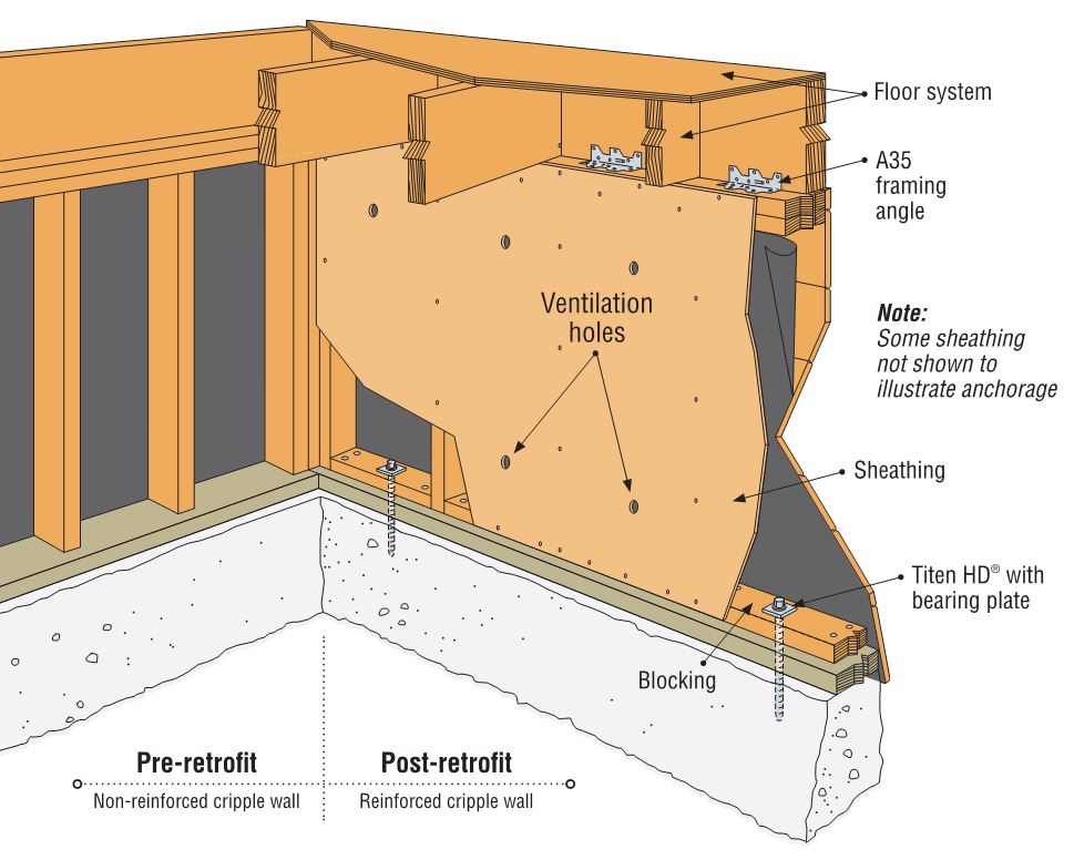
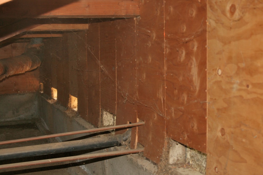
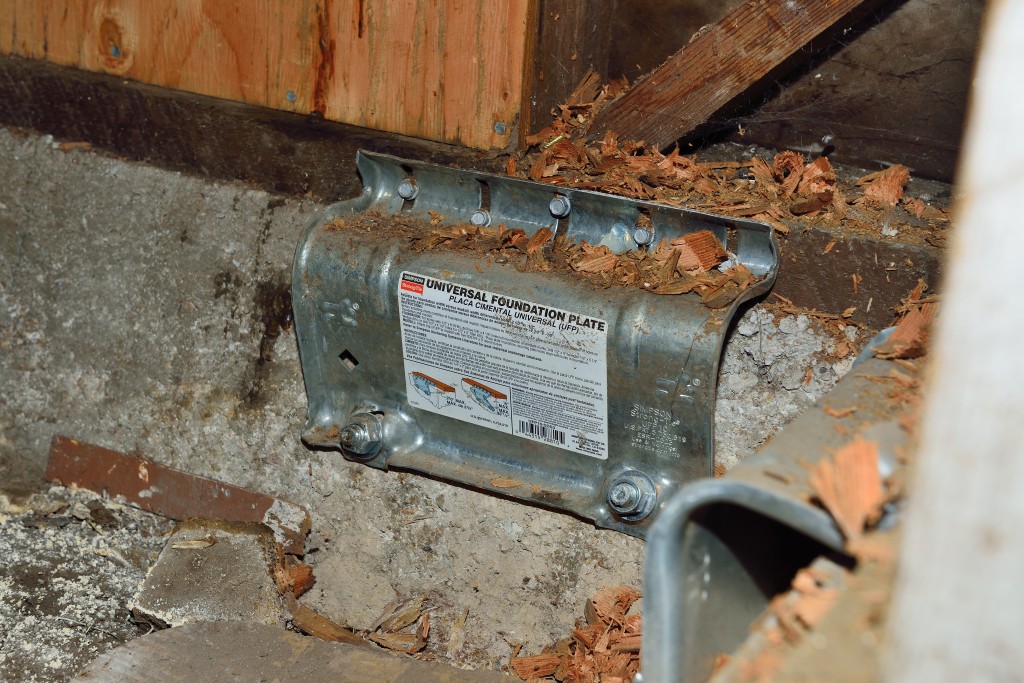
We’re also providing resources on how to retrofit homes and buildings, and have information for engineers at strongtie.com/softstory and for homeowners at safestronghome.com/earthquake.

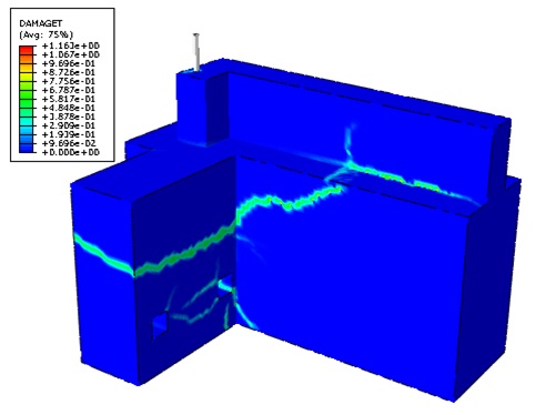
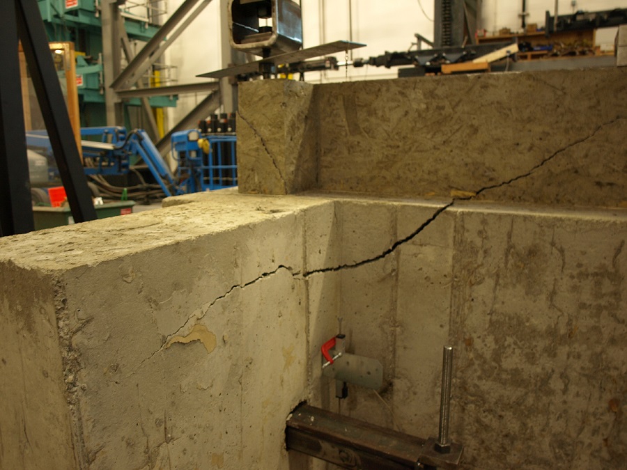
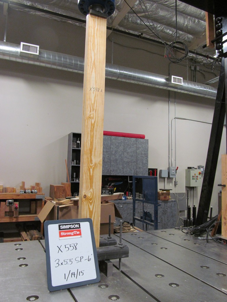
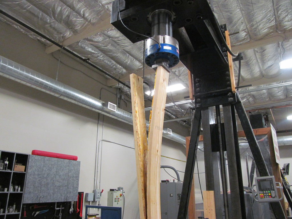
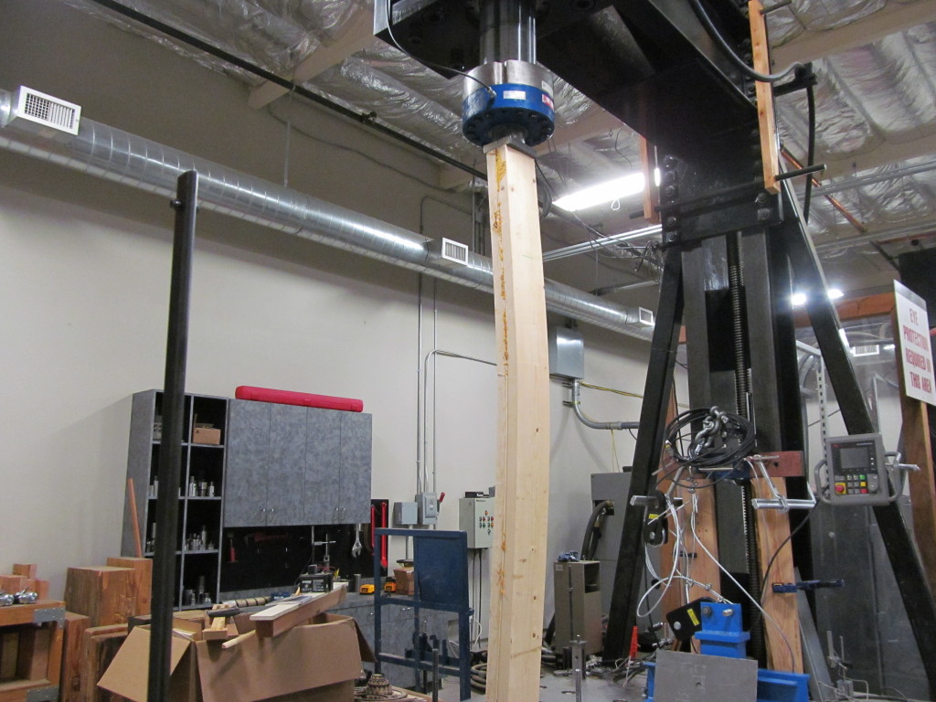
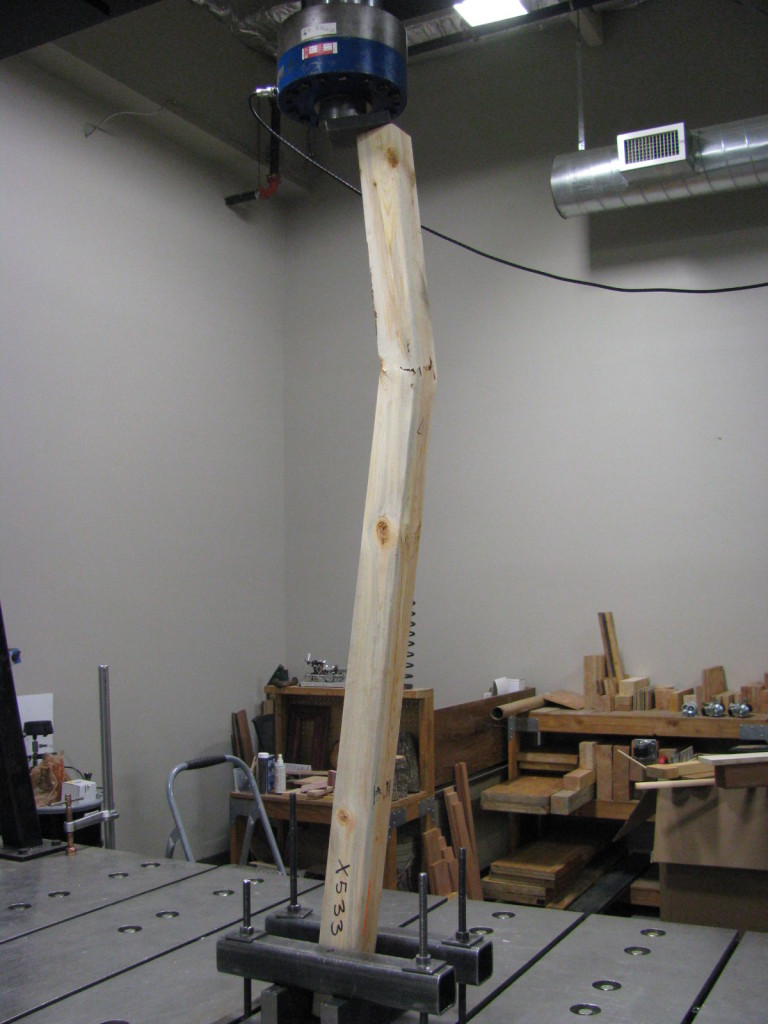
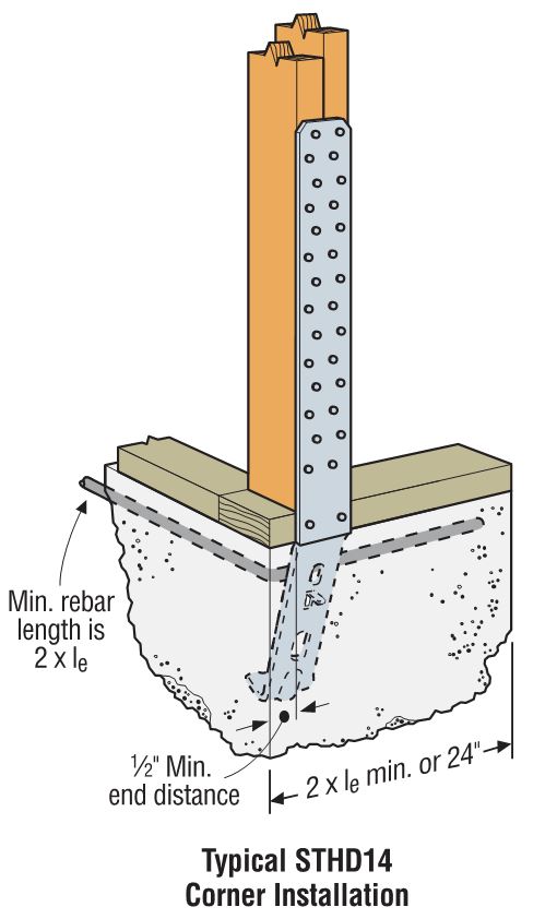
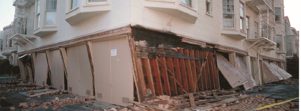
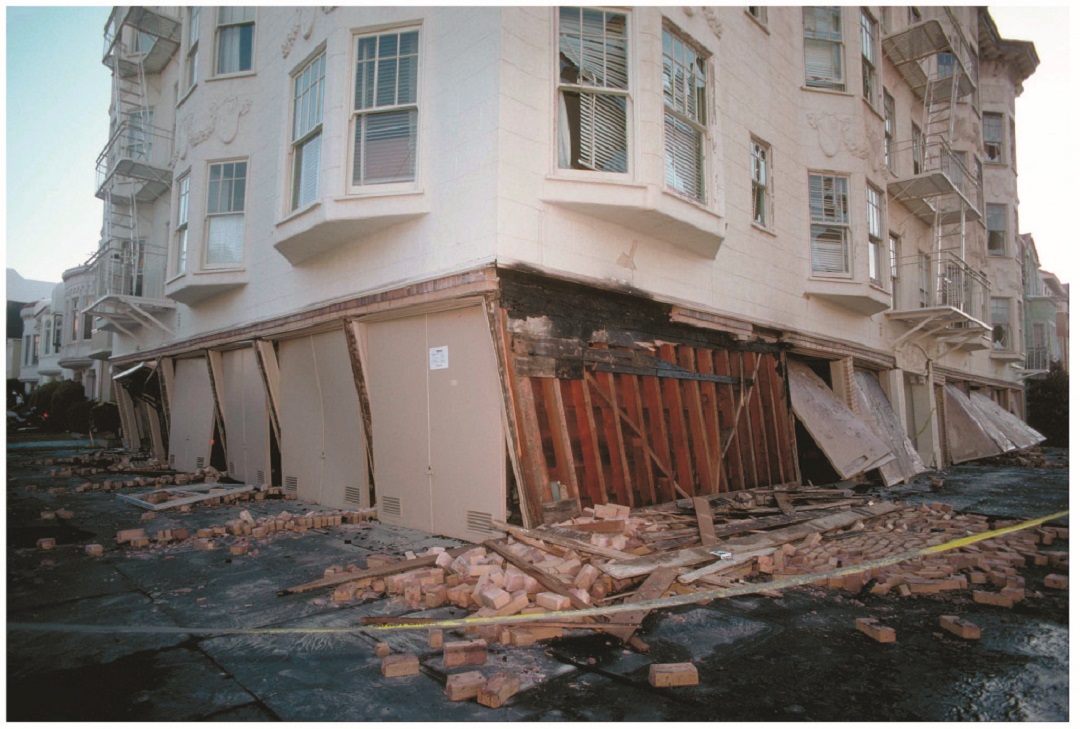
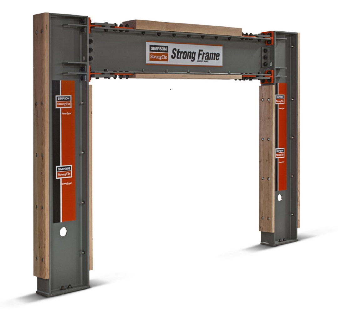
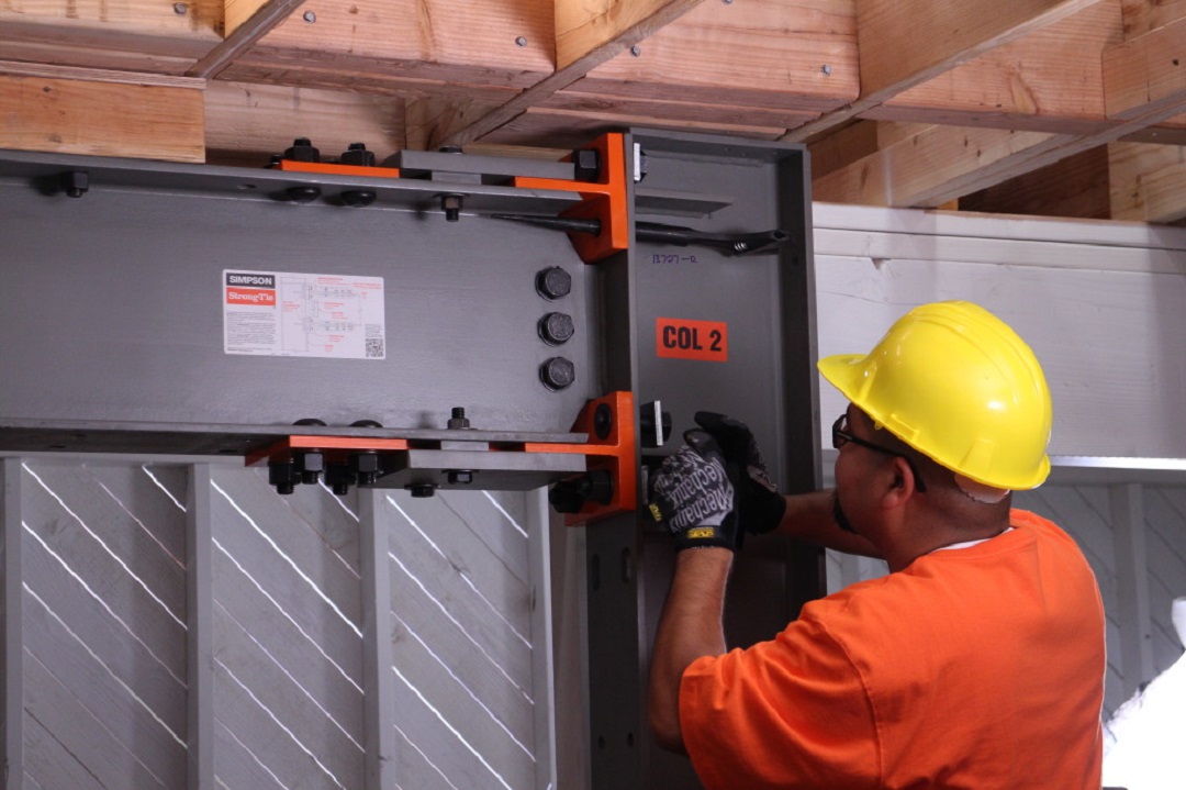
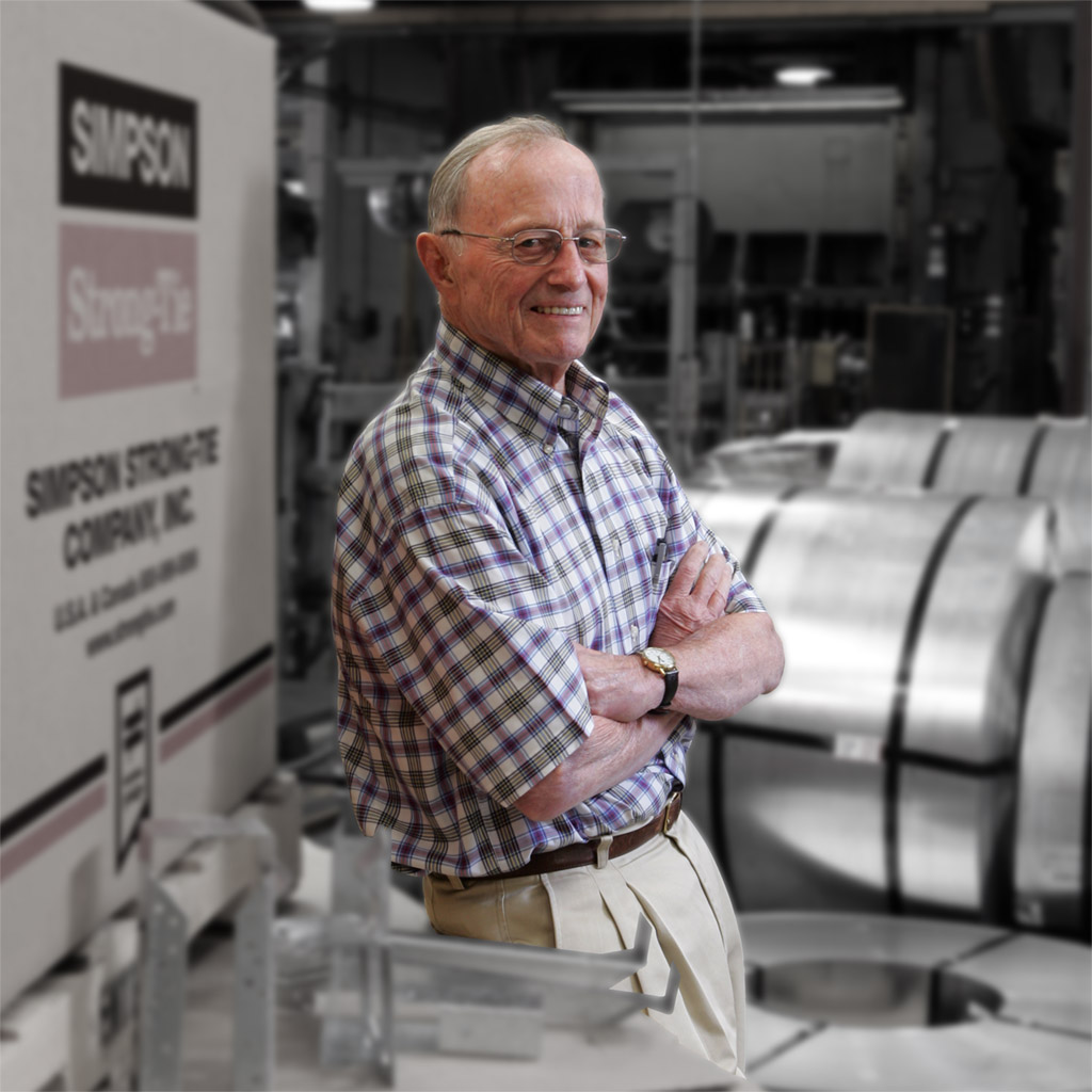
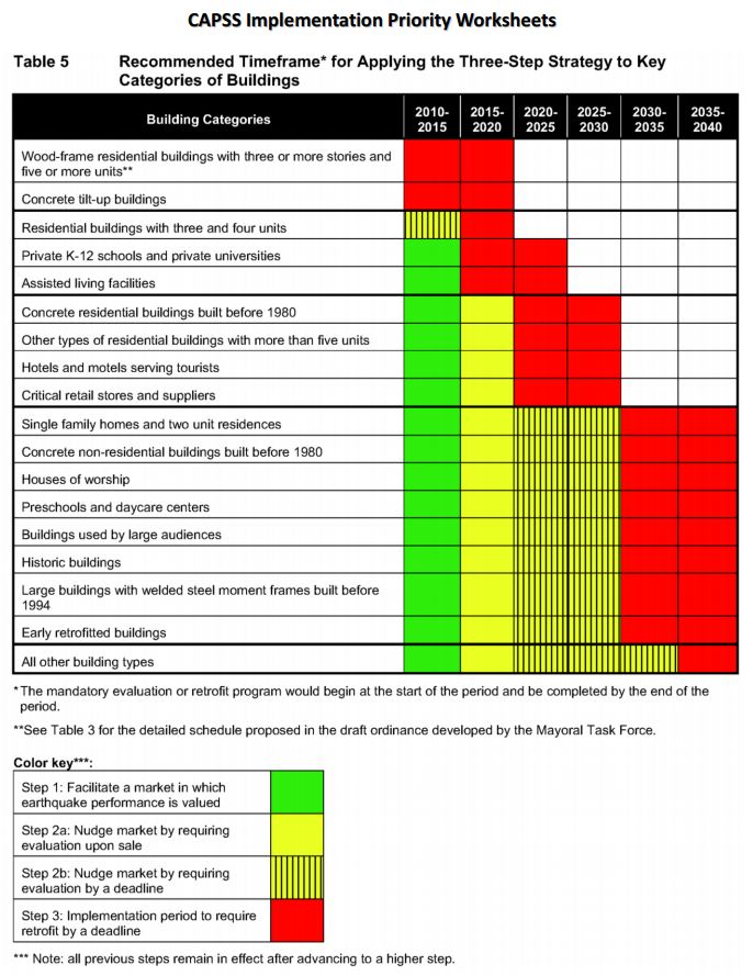
Earthquake risk is not just a California issue. According to the USGS, structures in 42 of 50 states are at risk for seismic damage. As many of you know, we have done a considerable amount of earthquake research, and are committed to helping our customers build safer, stronger homes and buildings. We continue to conduct extensive testing at our state-of-the-art Tye Gilb lab in Stockton, California, and next Wednesday, we’ll be performing a multi-story wall shake table test for a group of building officials at our lab. We are also working with the City of San Francisco to offer education and retrofit solutions to address their mandatory soft-story building retrofit ordinance and have created a section on our website to give building owners and engineers information to help them meet the requirements of the ordinance.

Soft Story Building with seismic damage.
Seismic damage to a soft-story building in San Francisco.

Our research is often in conjunction with academia. In 2009, we partnered with Colorado State University to help lead the world’s largest earthquake shake table test in Japan, demonstrating that mid-rise wood-frame buildings can be designed and built to withstand major earthquakes.

Earthquake articles like the one from The New Yorker also remind us how important it is to retrofit homes and buildings and to make sure homes, businesses, families and coworkers are prepared.

Like others in our industry, structural engineers play a role in increasing awareness about earthquake safety. We’d like to hear your thoughts about designing and retrofitting buildings to be earthquake resilient. Let us know in the comments below. And if your office hasn’t signed up for the Great ShakeOut Earthquake Drill, we encourage you to do so by visiting shakeout.org.

Continuous Rod Restraint Systems for Multi-Story Wood Structures

This week was our new employee Sales and Product Orientation class. It reminded me of the post A Little Fun with Testing where we broke a bowling ball. Although breaking stuff is fun, my second favorite part of the class is teaching about the importance of a continuous load path. I think it is really the most important thing a Structural Engineer does. If we don’t pay attention to the loads, where they occur and create a path so they can get where they need to go, a building may not stand up. This week, we also released some new tools and information for our new Strong-Rod™ Systems, which are used to complete the load path for multi-story wood-framed shearwall overturning restraint and roof uplift restraint.

Two Load Paths

All wood-framed buildings need to be designed to resist shearwall overturning and roof-uplift forces. To transfer these tensile forces through the load path, connectors (hurricane ties, straps and holdowns) have been the traditional answer. Simpson Strong-Tie offers a few options there.  With the growth in multi-story wood-framed structures, where the code requires shrinkage to be addressed and overturning and uplift forces are typically higher, rod systems have become an increasingly popular load restraint solution. Our Anchor Tiedown System (ATS) for shearwall overturning restraint has been around for many years. A new Strong-Rod Systems Design Guide and revamped web pages provide information on new design options, components and configurations.

Strong-Rod Systems Seismic and Wind Restraint Systems Guide

The guide and website focus more on the unique design considerations for rod systems, how you should specify the system and highlight the design services that we provide. They also provide more detail and design information for our relatively new Uplift Restraint System (URS) for roofs. Connectors are a common choice for transferring the net roof uplift forces from wind events down the structure. Although in some high-wind areas, rod systems are preferred.

ATS and URS Continuous Rod Tiedown Systems

I’ll touch on some of the design considerations for these types of systems below, but back to the load path. For shearwall overturning restraint using holdowns, the load path is fairly simple. Once the lateral load is in the shearwall, the sheathing and nailing lifts up on the post. The holdown connects to the post, holding it down and transferring the forces to the foundation or level below. A continuous rod tiedown system follows a little different path. The sheathing and nailing lifts up on the boundary posts and the posts push up on the framing above until the load is resisted in bearing by a bearing plate. The load is then transferred into the rod and down to the foundation. There has been a lot of testing and research on the effects of skipping restraint locations where a bearing plate restraint is installed at every other floor or only at the top level.  Doing that will change the load path because the load has to continue to travel up until a restraint holds it down. It also negatively impacts the stiffness and drift of the shearwall stack, not to mention increases project cost because the boundary posts, rod and bearing must be sized to transfer the cumulative overturning forces from each level.

ATS load path
ATS load path

Wood Shrinkage, Take-up Devices and Displacement Limits

Shrinkage is not just a Seinfeld episode cult classic. It is also something that designers need to consider when designing wood structures. IBC Section 2304.3.3 requires that designers evaluate the impact of wood shrinkage on the building structure when bearing walls support more than two floors and a roof. The effects of wood shrinkage can impact many things in the structure from finishes to MEP systems to the continuous rod system. As the wood members lose moisture, the wood shrinks and the building settles. This can cause gaps at the bearing plate locations of continuous rod systems because the continuous steel rod doesn’t shrink. That is where the magic of take-up devices comes in. They allow the building to shrink but keep gaps from forming by filling the gap (expanding devices – can be screw style or ratcheting), ratcheting down the rod (ratcheting devices), or making the rod shrink as much as the wood (contracting coupling device).


In addition to keeping the rod system tight to insure the intended performance, it is important to consider the movement associated with the rod system when under wind or earthquake loading. The IBC requires shearwall displacements to be within story drift limits in moderate to high seismic regions. We highlighted some of the changes coming for the evaluation of shearwall deflection in the previous post discussing the New Treatment of Shear Wall Aspect Ratios in the 2015 SDPWS. For continuous rod systems, there are some additional limits. ICC-ES AC316 Acceptance Criteria for Shrinkage Compensating Devices requires designs to limit displacement between restraints to 0.20 inches (including rod elongation and device displacement) for shearwall restraint. The movement of the take-up device plays a big part in meeting this requirement and the rod diameter required. Screw-style devices have the lowest total movement. Ratcheting devices are appropriate in many cases as well such as the upper levels where loads are lower, but may require larger rod diameters to meet the displacement limit.

figure5ICC-ES AC391 Acceptance Criteria for Continuous Rod Tie-down Runs and Continuous Rod Tie-down Systems Used to Resist Wind Uplift covers continuous rod systems for roof uplift restraint. The displacement limit for the Continuous Rod Tie-down Run (just the rod system components) is limited to 0.18 inches of rod elongation for the total length of rod. The Strong-Rod URS evaluates the Continuous Rod Tie-down System (the whole load path). Displacement limits for the system are L/240 for the top plate bending and 0.25 inches total deflection at the top plate between tie-down runs (including top plate bending, rod elongation, wood bearing deformation and take-up device displacement). The differences between the rod run and rod system analysis as well as other design considerations are explained in more detail in the design guide and on our website.

I always end my continuous load path presentation during orientation class with the same questions and if they were paying attention I get the response I want.

“What is the most important thing a Structural Engineer does?”

“Designs a continuous load path for the building!”

“What does Simpson Strong-Tie do?”

“Provides product and system solutions to help  engineers do their job!”

Take a look at the new Strong-Rod Systems tools and information and let us know how we can help you with your next multi-story wood-framed project.

What related blog topics would you like to discuss? Let us know in the comments below.

Holdown Anchorage Solutions

A common question we get from specifiers is “What anchor do I use with each holdown?” Prior to the adoption of ACI 318 Appendix D, this was somewhat simple to do. We had a very small table near the holdown section of our catalog that listed which SSTB anchor worked with each holdown.

The good old days! (Don’t use this today.)

During the good old days, anchor bolts had one capacity and concrete wasn’t cracked. ACI 318 Appendix D gives us reduced capacities in many situations, different design loads for seismic or wind and reductions for cracked concrete. These changes have combined to make anchor bolt design more challenging than it was under the 1997 Uniform Building Code.

This blog has had several posts related to holdowns. So, What’s Behind a Structural Connector’s Allowable Load? (Holdown Edition) explained how holdowns are tested and load rated in accordance with ICC-ES Acceptance Criteria. Damon Ho did a post, Use of Holdowns During Shearwall Assembly, which discussed the performance differences of shearwalls with and without holdowns, and Shane Vilasineekul did a Wood Shearwall Design Example. So I won’t get in to how to pick a holdown.

Once you have determined your uplift requirements and selected a post size and holdown, it is necessary to provide an anchor to the foundation. To help Designers select an anchor that works for a given holdown, we have created different tables that provide anchorage solutions for Simpson Strong-Tie holdowns.

SSTB Anchor Bolt
SSTB Anchor Bolt
SB Anchor Bolt
SB Anchor Bolt

There is one Engineering letter that addresses slab-on-grade foundations and another version that covers stemwall foundations. The tables are separated by wood species (DF/SP and SPF/HF) to give the most economical anchor design for each post material. The preferred anchor solutions are SSTB or SB anchors, as these proprietary anchor bolts are tested and will require the least amount of concrete. When SSTB or SB anchors do not have adequate capacity, we have tabulated solutions for the PAB anchors, which are pre-assembled anchors that are calculated in accordance with ACI 318 Appendix D.

Slab On Grade Anchorage Solutions
Stemwall Anchorage Solutions

The solutions in the letters are designed to match the capacity of the holdowns, which allows the contractor to select an anchor bolt if the engineer doesn’t specify one. They are primarily used by engineers who don’t want to design an anchor or select one from our catalog tables. We received some feedback from customers who were frustrated that some of our heavier holdowns required such a large footing for the PAB anchors, whereas a slightly smaller holdown worked with an SB or SSTB anchor in a standard 12″ footing with a 1½” pop out.

6-in Popout FEA Model
6-in Popout Physical Testing

To achieve smaller footings using our SB1x30 anchor bolts, we reviewed our original testing and created finite element (FEA) models to determine what modifications to the slab-on-grade foundation details would meet our target loads. Of course, we ran physical tests to confirm the FEA models. With a 6″ pop out, we were able to achieve design loads for HD12, HDU14 and HHDQ14.

HD12, HDU14 & HHDQ14 Solutions
HD12, HDU14 and HHDQ14 Solutions

The revised footing solutions for the heavier holdowns require less excavation and less concrete than the previous Appendix D calculated solutions, reducing costs on the installation.

What has been your experience with holdown anchorage? Tell us in the comments below.

More Fun with Testing

A couple of years back, I did a blog post with a video of a bowling ball exploding. It’s a fun test to show guests who visit our connector lab. Of course, we also do a joist hanger or holdown test to demonstrate a real test used to load rate our products. The problem is some of our tests just aren’t too exciting to the general population. It’s a bit anticlimactic when the wood slowly crushes or the fasteners withdraw until the test specimen just can’t take any load. But bowling balls explode, and explode fast!

In the last couple of months, our connector test lab ran a number of built-up post compression tests. We were looking for data to compare the performance of built-up posts whose members were fastened with connectors (nails, screws, or bolts) to posts that were glued together.

Southern Pine Built Up Setup
Southern Pine Built-up Setup


Southern Pine Built Up Failure
Southern Pine Built-up Failure


Spruce-Pine-Fir 2x6 Built Up Post
Spruce-Pine-Fir 2×6 Built-up Post


Spruce-Pine-Fir 2x4 Built Up
Spruce-Pine-Fir 2×4 Built-up Post

Our test presses have compression capacities ranging from 100 kips to 200 kips. While we have tested some really heavy connectors, most of our tests are under 50 kips ultimate load. The built-up post testing was exciting to watch as loads got as high as 180 kips and had some very dramatic failures. More fun than the bowling balls, but a little more difficult to contain the explosions.

I have no numbers to share from this testing, as design procedures exist in the code for built-up posts. A few non-technical things we learned from doing this built-up post testing include:

  • Short posts can take a lot of load
  • Regular wood glue requires careful application to get good bond over the full area of a board
  • We haven’t mastered glue application
  • Posts can explode
  • Heavy steel plates go flying when posts explode

Not scientific, but fun to watch. The videos were captured on an iPhone by R&D Lab Testing Technician Steve Ziagos. Steve also blogs about Do-It-Yourself projects on our DIY Done Right blog. Enjoy the video.


Anchor Testing for Light-Frame Construction

I started off doing a four-part series on how connectors, fasteners, concrete anchors and cold-formed steel products are tested and load rated. I realized that holdown testing and evaluation is quite a bit different than wood connector testing, so there was an additional post on holdowns. We have done several posts on concrete anchor testing (here and here), but I realize I never did a proper post about how we test and load rate concrete products per ICC-ES AC398 and AC399.

AC398 – Cast-in-place Cold-formed Steel Connectors in Concrete for Light-frame Construction and AC399 – Cast-in-place Proprietary Bolts in concrete for Light-frame Construction are two acceptance criteria related to cast-in-place concrete products.

Cold-formed steel connectors embedded in concrete are not considered in ACI 318 Appendix D, so it was necessary to create criteria for evaluating those types of connectors. Some examples of products covered by AC398 are the MASA mudsill anchor, CBSQ post base, and the STHD holdown.

MASA mudsill anchor
MASA mudsill anchor
CBSQ post base
CBSQ post base
STHD holdown
STHD holdown

ACI 318 Appendix D addresses the design of cast-in-place anchors. However, the design methodology is limited to several standard bolt types.

ACI 318 Appendix D Cast-in anchors

There are a number of anchor bolt products that have proprietary features that fall outside the scope of ACI 318, so AC399 fills in that gap by establishing test procedures to evaluate cast-in-place specialty anchors. Simpson Strong-Tie SB and SSTB anchor bolts are two families of anchors we have tested in accordance with AC399.

SB Anchor Bolt
SB Anchor Bolt
SSTB Anchor Bolt
SSTB Anchor Bolt

SB and SSTB anchors have a sweep geometry which increases the concrete cover at the anchored end of the bolt, allowing them to achieve higher loads with a 1¾” edge distance. The SSTB is anchored with a double bend, whereas the SB utilizes a plate washer and double nut.

AC398 (concrete connectors) and AC399 (proprietary bolts) are similar in their test and evaluation methodology. AC398 addressing both tension and shear loads, whereas AC399 is limited to tension loads. Testing requires a minimum of 5 test specimens. These are the allowable load equations for AC398 and AC399:

AC398 - Allowable Load Equation
AC398 – Allowable Load Equation
AC399 - Allowable Load Equation
AC399 – Allowable Load Equation

For comparison, here is the standard AC13 allowable load equation for joist hangers:

Allowable Load = Lowest Ultimate / 3

Without getting into Greek letter overload, what are these terms doing?

Nu (or Vu) is the average maximum tested load. Calculating averages is something I actually remember from statistics class. Everything else I have to look up when we do these calculations.

(1 – K x COV) uses K as a statistical one-sided tolerance factor used to establish the 5 percent fractile value with 90% confidence. This term is to ensure that 95% of the actual tested strengths will exceed the 5% fractile value with 90% confidence. COV is the coefficient of variation, which is a measure of how variable your test results are. For the same average ultimate load, a higher COV will result in a lower allowable load.

The K value is 3.4 for the minimum required 5 tests, and it reduces as you run more tests. As K decreases, the allowable load increases. In practice, we usually run 7 to 10 tests for each installation we are evaluating.

Table A2.1 – K values for evaluating the characteristic capacity at 90% confidence

Rd is seismic reduction factor, 1.0 for seismic design category A or B, and 0.75 for all others. This is similar to what you would do in an Appendix D anchor calculation, where anchor capacities in higher seismic regions are reduced by 0.75.

Rs and Rc are reduction factors to account for the tested steel or concrete strength being higher than specified. There are some differences in how the two acceptance criteria apply these factors, which aren’t critical to this discussion. Φ is a strength reduction factor, which varies by failure mode and construction details. Brittle steel failure, ductile steel failure, concrete failure and the presence of supplemental reinforcement.

The α factor is used to convert LRFD values to ASD values. So α = 1.0 for LRFD and α = 1.4 for seismic and 1.6 for wind. Both criteria also allow you to calculate alpha based on a weighted average of your controlling load combinations. This has never made a lot of sense to me in practice. If you are going to work through the LRFD equations to get a different alpha value, you might as well do LRFD design.

MASA - Test Setup MASA - Test Failure

Rse is a reduction factor for cyclic loading, which is applied to proprietary anchor bolts covered under AC399, such as the SSTB or SB anchors. A comparison of static load and cyclic load is required for qualification in Seismic Design Category C through F. Unlike the cracked reduction factor, manufacturers cannot take a default reduction if they want recognition for high seismic.

Due to the differences in AC398 and AC399 products, the load tables are a little different. AC398 products end up with 4 different loads – wind cracked, wind uncracked, seismic cracked and seismic uncracked.

CBSQ Load Table
CBSQ Load Table

AC399 products are a little simpler, having just wind and seismic values to deal with.

SSTB Load Table
SSTB Load Table

What are your thoughts? Let us know in the comments below.

Seismic Safety Regulations and Solutions

I have a special place in my heart for old buildings. Every college design course I took was related to new design. Concrete, steel, or wood design, the design problem was invariably part of a new building. I thought structural engineers designed new buildings. When I showed up for my first day of work wearing dress pants, a button-down shirt and a tie, I was handed a flashlight, tape measure, a clipboard and a Thomas Guide map (no Google maps back then) and sent to do as-built drawings for a concrete tilt-up that we were retrofitting.

When I was designing buildings, I created a lot of as-built drawings. Figuring out how a building was put together, what the structural system was (or wasn’t!) and designing a lateral load path in these old, and often historic buildings, was immensely satisfying. Knowing that history, it should not be surprising I have done a number of blog posts related to seismic retrofits. Soft-Story Retrofits, San Francisco’s Soft-Story Retrofit Ordinance, Remembering Loma Prieta, Resilient Communities, FEMA P-807, and Home Seismic Retrofit (there are probably a couple I forgot).

This week, Los Angeles Mayor Eric Garcetti proposed new seismic safety regulations . The recommendations are to retrofit soft-story wood-framed buildings within five years and older concrete buildings within 30 years. While these are only recommendations, it is encouraging to see politicians supporting policies to promote resiliency and life safety.

In San Francisco, thousands of building owners are already required by law to seismically retrofit multi-unit (at least five) soft-story, wood-frame residential structures that have two or more stories over a “soft” or “weak” story. These buildings typically have parking or commercial space on the ground floor with two or more stories above. As a result, the first floor has far more open areas of the wall than it actually has sheathed areas, making it particularly vulnerable to collapse in an earthquake.

Photo credit: J.K. Nakata and the U.S. Geological Survey

San Francisco’s ordinance affects buildings permitted for construction before Jan. 1, 1978. Mandatory seismic retrofit program notices requiring that buildings be screened were sent out in September, 2013, to more than 6,000 property owners. It is anticipated that approximately 4,000 of those buildings will be required to be retrofitted by 2020.

“When we look at the demographic of these buildings, they house approximately 110,000 San Franciscans. It’s paramount that we have housing for people after a disaster. We know we will see issues in all types of buildings, but this is an opportunity for us to be able to retrofit these buildings while keeping an estimated 1100,000 San Franciscans in their homes and, by the way of retrofit, allowing them to shelter in place after a disaster,” according to Patrick Otellini, San Francisco’s chief resilience officer and director of the city’s Earthquake Safety Implementation Program. “This exponentially kick starts the city’s recovery process.”

One solution to strengthen such buildings is the Simpson Strong-Tie® Strong Frame® special moment frame. Its patented Yield-Link™ structural fuses are designed to bear the brunt of lateral forces during an earthquake, isolating damage within the frame and keeping the structural integrity of the beams and columns intact.

Simpson Strong-Tie® Strong Frame® special moment frame

“The structural fuses connect the beams to the columns. These fuses are designed to stretch and yield when the beam twists against the column, rather than the beam itself, and because of this the beams can be designed without bracing. This allows the Strong Frame to become a part of the wood building and perform in the way it’s supposed to,” said Steve Pryor, S.E., International Director of Building Systems at Simpson Strong-Tie. “It’s also the only commercially-available frame that bolts together and has the type of ductile capacity that can work inside of a wood-frame building.”

Installation of the Simpson Strong-Tie® Strong Frame® special moment frame

Another key advantage of the Simpson Strong-Tie special moment frame is no field welding is required, which eliminates the risk of fire in San Francisco’s older wood-framed buildings.

To learn more about San Francisco’s retrofit ordinance, watch a new video posted on strongtie.com/softstory. For more information about the Strong Frame special moment frame, visit strongtie.com/strongframe.

Remembering Barclay Simpson

On Saturday evening, Barclay Simpson passed away peacefully in his sleep, surrounded by his family. He was 93 years old. With Barc’s passing, Simpson Strong-Tie has lost a beloved and inspirational leader. Our country has lost a generous philanthropist, visionary and great American entrepreneur. Those of us who were fortunate enough to know and work with Barc have lost a dear friend, champion and guide.

Barc’s contributions to the construction industry, non-profit community and our employees are immeasurable. He instilled the core values — our “Secret Sauce” — that have made Simpson Strong-Tie a unique and inspiring place to work and have built our reputation as a quality, trusted manufacturer and solid corporate citizen.

Barclay Simpson

The first time I met Barc was less than a week after I started working in the R&D department. I was meeting with a product manager and Barc was walking by, so he stopped in to say hello. We introduced ourselves and chatted for a few minutes. I told him about my work experience, where I went to school, what I was working on, and he even asked where I grew up. He was genuinely interested in getting to know me, which made me feel welcome.

I later noticed that Barc usually parked at the end of the building furthest from his office. He would take a different path through the building – sometimes through engineering, other times he would walk through marketing, accounting, or even the connector test lab. Barc cared deeply for all of his employees, and the intentionally long walk gave him the opportunity to talk with folks.

He firmly believed that everybody in the company is important, and he took every opportunity to remind us. In the video, Barclay Simpson’s Nine Principles of Doing Business, Barc speaks quite passionately about dignifying the contribution of every individual at every level.

In the end of a previous blog post, I mentioned Barc’s 1974 list of Rambling Thoughts on Making One’s Fleeting Moment on This Planet a Pleasant One. In the context of that post, the thoughts of “Attitude Conquers All” and “Keep it light. It really isn’t that important” were appropriate.

Thinking of Barc and his legacy, I prefer this rambling thought from his list:

Strive to have a POSITIVE EFFECT upon those lives touched by your own.

Innovative Screws Are Replacing Bolts

In the past several years, there has been an increase in the use of screws in applications that have traditionally been reserved for bolts and lag screws. Greater innovation in the wood screw market has caused this shift. Proprietary wood screws now offer many more benefits than commodity bolts and lag screws. Today, this post will discuss some of those benefits.

Continue Reading

Home Seismic Retrofit

The 6.0 magnitude earthquake that struck Napa, CA, in August caused more than 200 injuries and structural damage to many homes and businesses throughout the area. The quake was the largest to hit the San Francisco Bay Area since the Loma Prieta earthquake (6.9 magnitude) in 1989, prompting the governor to declare a state of emergency.

I have done several posts about San Francisco’s Soft-Story Retrofit Ordinance and some of NEES-Soft testing related to soft-story retrofits. The soft-story ordinance only addresses multi-unit residential units and does not require retrofit of single-family homes. Cities are reluctant to mandate seismic evaluation and retrofit of single-family homes for a number of reasons that I won’t discuss here. The draft Earthquake Safety Implementation Program (ESIP) for San Francisco will not recommend mandatory retrofit of single-family homes until 2030.

CAPSS Implementation Priority Worksheet

The good news is homeowners can retrofit their homes without waiting for the government. A couple years ago in this post, I discussed some of the tools available to retrofit existing buildings.

One of these tools is the 2012 International Existing Building Code (IEBC). The IEBC has provisions for repair, alteration, addition or change of occupancy in existing buildings and for strengthening existing buildings. For alterations, these provisions may not comply with current IBC requirements, but they are intended to maintain basic levels of fire and structural life safety. The IEBC also provides prescriptive provisions for strengthening existing buildings against earthquake damage, which include strengthening residential houses on raised or cripple wall foundations.

Cripple Wall Reinforcing Schematic

Cripple Wall Retrofit Schematic and Installation

Cripple wall failures are a common type of damage observed in older homes, caused by inadequate shear strength in the cripple wall. An additional failure point is the attachment of the wood sill plate to the foundation. Having a strong connection between the wood structure and the concrete foundation is critical in an earthquake. Since the work required to strengthen these connections is typically performed in a crawlspace or unfinished basement, it is a relatively low-cost upgrade that is extremely beneficial to structural performance.

Retrofit with UFP Foundation Plate in Napa

Our website has information for retrofitting your home. The Seismic Retrofit Guide has information about how earthquakes affect a home and the steps to take to reinforce the structural frame of a house. The Seismic Retrofit Detail Sheet is intended to help building departments, contractors and homeowners with seismic retrofitting. It includes common retrofit solutions for reinforcing cripple walls and foundation connections.

One business owner in Napa chose to retrofit her building when she purchased it. You can see her video narrative here.