Purpose
The intent of this technical bulletin is to clarify code language and outline the correct path for the design of concrete anchors under the International Building Code (IBC). The reader will be able to clearly distinguish between “code anchors” and anchors that are considered “alternative materials,” as well as understand the logical sequence of code language for designing each type. The distinction between “cracked” concrete and “uncracked” concrete anchor design will be made. This technical bulletin will lend clarity to the qualification of post-installed anchors for use in concrete. Excerpts from the IBC and its Referenced Standards will be provided to facilitate the description of the design requirements.
Background
More than a decade after the introduction of the American Concrete Institute’s ACI 318, Appendix D design methodology for anchor design in 2002, many design professionals either do not fully understand or are unaware of the code requirements for the design of concrete anchors. Several factors contribute to the challenges associated with understanding the code mandates:
1. The incorrect notion that ACI 318, Appendix D is exclusively for anchors designed for “cracked concrete,” leading to regionally varying degrees of enforcement and implementation of the design requirements
2. Multiple Reference Standards for the design and qualification of different anchor types
3. The evolving scope of Reference Standards, which have reclassified some anchors as “Code Anchors” that were previously considered “Alternative Materials”
4. Confusing language in IBC sections that address concrete anchorage
5. Complexity of the anchor design methodology itself
6. Varying levels of special inspections enforcement
It is nevertheless incumbent upon the licensed design professional to design anchors in accordance with the minimum provisions of the code in order to protect public safety, reduce liability risk and fulfill professional responsibilities.
The International Building Code, beginning with the 2000 edition, describes the design methodology of concrete anchors by virtue of the language within the IBC itself, or through language in the Referenced Standard (ACI 318). In this technical bulletin, specific reference to the 2024 IBC and ACI 318-19 will be made, since this is currently the most widely adopted edition of the IBC.
“Code Anchors” and “Alternative Materials”
Anchors can be divided into two major categories: 1) “Code Anchors”, which are those that are specifically addressed in the IBC or its Referenced Standards, and 2) “Alternative Materials”, the design and qualification of which are not addressed in the IBC or its Referenced Standards.
The following “Code Anchors” recognized by the 2024 IBC:
- Headed studs
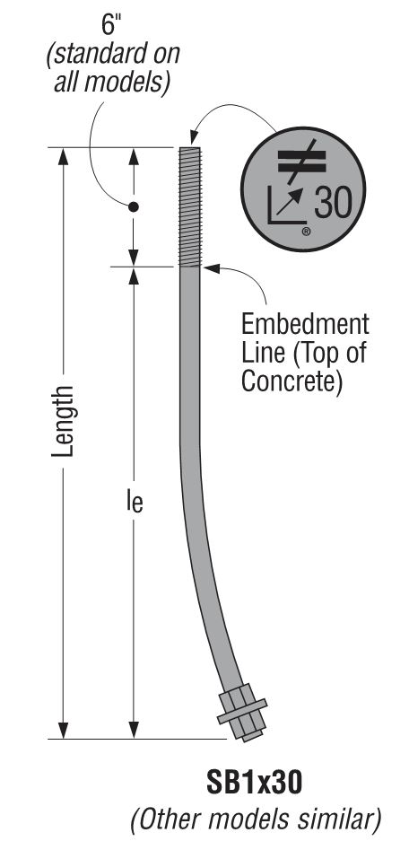
- Headed bolts
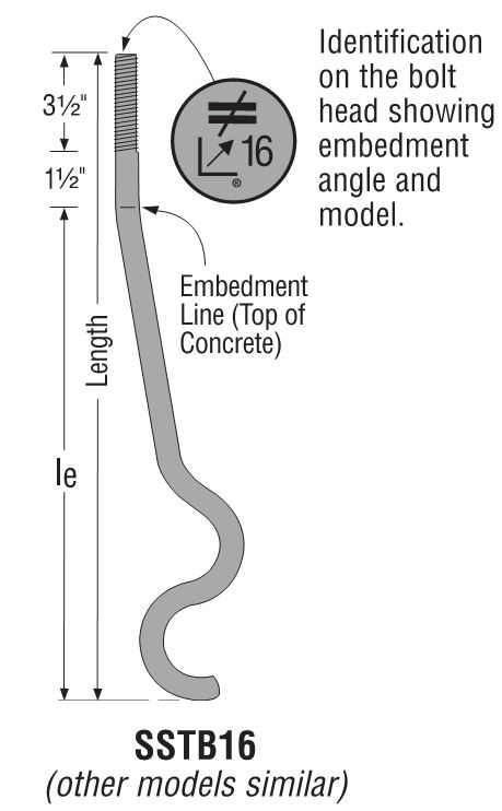
- Hooked (J- or L-) bolts
- Expansion anchors (such as Simpson Strong-Tie® Strong-Bolt® 2)
- Undercut anchors
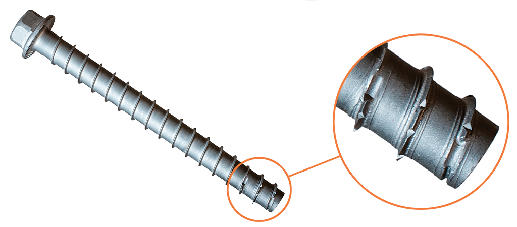
- Screw anchors (such as Simpson Strong-Tie® Titen HD®)
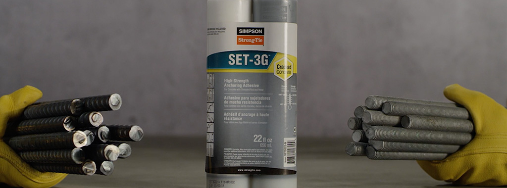
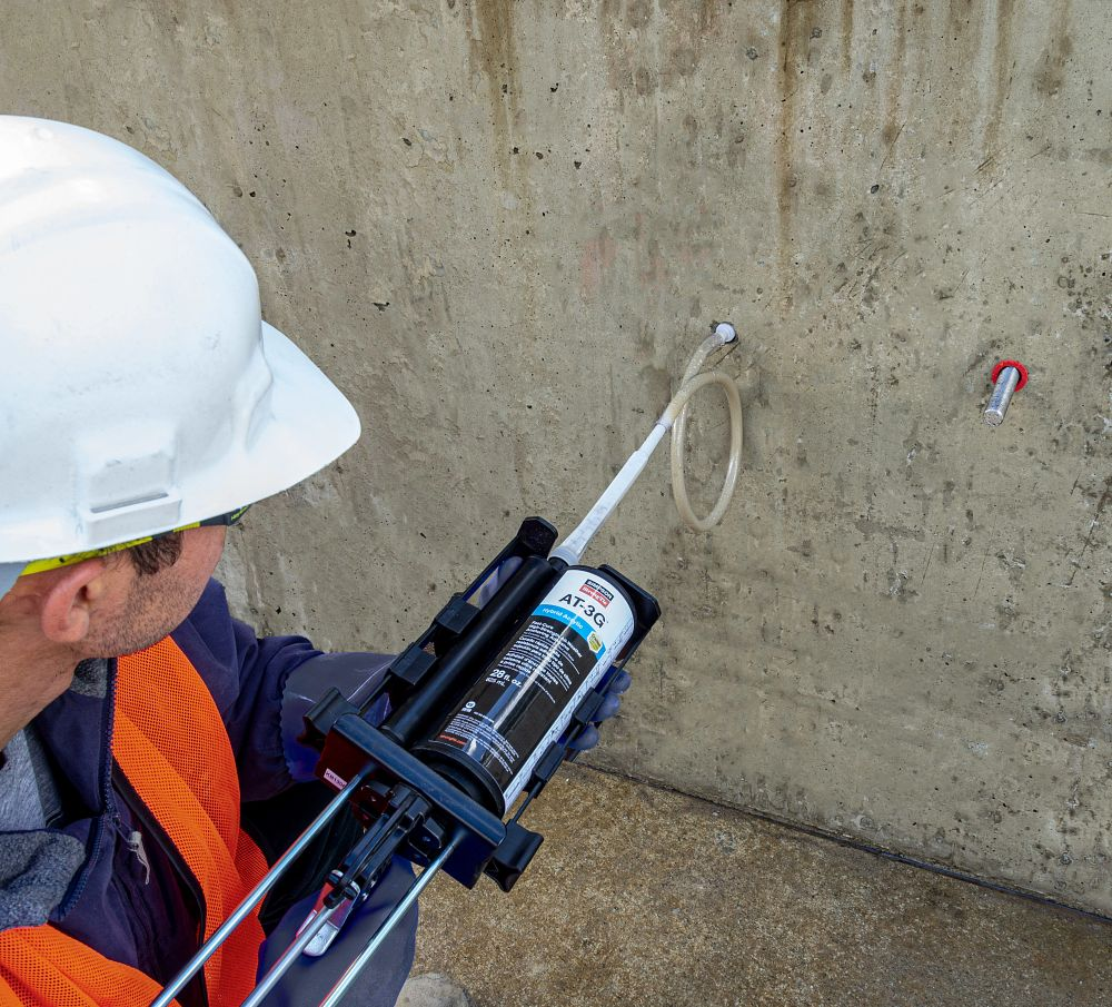
- Adhesive anchors (such as Simpson Strong-Tie® ET-3G™, AT-3G™ and SET-3G®)

Anchor types not listed above are considered “Alternative Materials.”
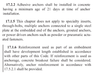
Alternative materials also apply to anchor types specifically excluded from ACI 318-19 calculation and analysis requirements.
- Specialty inserts
- Through-bolts
- Multiple anchors connected to a single steel plate at the embedded end
- Grouted anchors
- Powder- or gas-actuated fasteners (such as Simpson Strong-Tie® PDPA)

Designing “Code Anchors”
The starting point for the design of all anchors is Section 1901.3 and Section 1905 of the 2024 IBC, which reference ACI 318-19 Chapter 17 for anchorage design requirements.

Under the 2024 IBC, anchor design is governed by Section 1901.3 and Section 1905, which reference ACI 318-19 Chapter 17. Chapter 17 establishes a comprehensive strength design (LRFD) approach for anchoring to concrete, rather than traditional “Allowable Stress Design” (ASD). It provides detailed equations for steel strength, concrete breakout, pullout, and pryout failure modes for both cast-in and post-installed anchors, applying strength reduction factors (ϕ) and load factors (γ). For general calculations, the compressive strength of concrete (f’c) is limited to 8,000 psi.
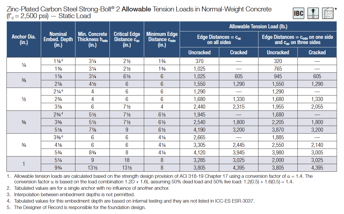
While Chapter 17 is fundamentally strength design, some anchor product evaluations – such as ICC-ES Evaluation Reports (ESRs) or Technical Engineering Bulletins (TEBs) – include ASD tables derived from ACI 318 strength design equations. These tables use specific footnotes and conversion factors to present allowable service loads, and may incorporate additional safety factors or seismic overstrength factors (Ω0). Designers must carefully review these footnotes to confirm whether values represent strength design capacities or manufacturer-provided allowable loads, and ensure compliance with the applicable code edition.
In essence, ACI 318-19 Chapter 17 sets the governing rules for strength design, while manufacturers bridge the gap for projects requiring allowable loads through ESRs or TEBs. Regardless of format, all anchors – cast-in or post-installed – must meet the qualification standards in ACI 355.2 (mechanical anchors) and ACI 355.4 (adhesive anchors), and comply with the performance requirements referenced by the IBC.
Anchors resisting earthquake loads or effects must be designed using strength design in accordance with ACI 318-19 Chapter 17, as referenced by 2024 IBC Section 1901.3 and Section 1905. This includes cast-in headed bolts, headed studs, hooked bolts, and post-installed anchors such as mechanical and adhesive anchors. Adhesive anchors are explicitly included in ACI 318-19 and must meet installation and qualification requirements defined in ACI 355.4, with special provisions for sustained tension and seismic applications. The design professional must confirm that anchors fall within the scope of ACI 318-19 Chapter 17 and meet all seismic and load combination provisions. Post-installed anchors must also satisfy qualification standards and be supported by ICC-ES Evaluation Reports (ESRs) or equivalent documentation to confirm compliance.


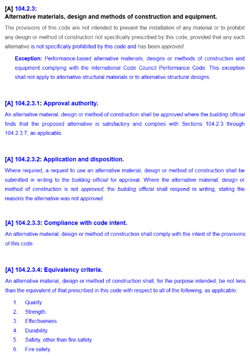
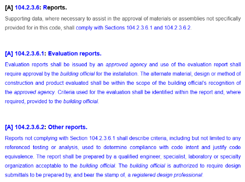
Anchors used for temporary construction purposes, such as tilt-up wall panel bracing, are not addressed by the anchorage provisions of the IBC and therefore are not required to be designed in accordance with ACI 318-19 Chapter 17. Chapter 17 clearly defines the scope of anchors covered by the code, including cast-in and post-installed anchors (mechanical and adhesive), and identifies anchor types that fall outside its requirements. Anchors excluded from Chapter 17 are considered alternative materials and must be evaluated and approved under the provisions of 2024 IBC Section 104.2.3, which allows alternative materials and methods when they provide equivalent performance to code requirements.
Code Anchors are required to meet the ACI 318-19 Section 17.1.2 qualification requirements described below.

ACI 355.2 (Qualification standard for expansion, undercut, and screw anchors) and ACI 355.4 (Qualification standard for adhesive anchors) are referenced here as the qualification criteria for specific types of post-installed anchors. For the design professional it can be difficult to determine, without fully investigating these Referenced Standards, whether a specific proprietary anchor has been tested and is qualified for use in concrete. A simpler means by which to identify whether a proprietary anchor has been qualified to the Referenced Standard is a current Research Report (e.g., Evaluation or Code Report) which provides third-party review and verification that the product has been tested to and meets the qualification standard. There are two primary Research Report providers: IAPMO UES (International Association of Plumbing & Mechanical Officials Uniform Evaluation Service) and ICC-ES (International Code Council Evaluation Service).
These agencies are ANSI ISO 17065 accredited. They review independent laboratory test data, witnessed or conducted by an accredited third party, for a product and verify its conformance to publicly developed and majority-approved qualification criteria (or acceptance criteria) established for a given anchor type. Research Reports are an invaluable tool to the design professional and building official as evidence of conformance with the IBC.
There are two acceptance criteria that apply to post-installed “Code Anchors”:
- ICC-ES AC193 – Acceptance Criteria for Post-Installed Mechanical Anchors in Concrete Elements
- ICC-ES AC308 – Acceptance Criteria for Post-Installed Adhesive Anchors in Concrete Elements
These acceptance criteria reference ACI 355.2 and ACI 355.4, respectively, as the foundation for the test program by which the anchor is evaluated, and establish minimum performance standards for qualification. A Research Report is issued for an anchor that meets these minimum standards.