


Back in April of last year, I had the opportunity to show how our new CFS Designer software could help structural engineers “go lean” in their design process by eliminating repetitive tasks (while still meeting required design standards, of course!). Since then, I’ve had the opportunity to visit with hundreds of engineers in person to teach them about CFS Designer and how it can help them improve and optimize their workflows. As a power user of the software, I want to share my top tips for letting CFS Designer help you save the maximum amount of time.
Continue Reading
Category: Connectors
With nearly 70 years of field and R&D experience, Simpson Strong-Tie® connectors are manufactured to the industry’s highest standards. From framing angles to straps to heavy-duty girder hangers, we offer the most diverse product line so that you have the right product for the job. Find out how Simpson Strong-Tie connectors can help you build the right way every day.
Decrypting Cold-Formed Steel Connection Design
As published in STRUCTURE magazine, September 2016. Written by Randy Daudet, P.E., S.E., Product Manager at Simpson Strong-Tie. Re-posted with permission.
One of the world’s greatest unsolved mysteries of our time lies in a courtyard outside of the Central Intelligence Agency (CIA) headquarters in Langley, Virginia. It’s a sculpture called Kryptos, and although it’s been partially solved, it contains an inscription that has puzzled the most renowned cryptanalysts since being erected in 1990. Meanwhile, in another part of the DC Beltway about 15 miles to the southeast, another great mystery is being deciphered at the American and Iron Institute (AISI) headquarters.Continue Reading
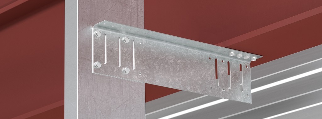
New Moment-Resisting Post Base
At Simpson Strong-Tie, we strive to make an engineer’s life easier by developing products that help with design efficiency. Our products are designed and tested to the highest standards, and that gives structural engineers the confidence that they’re using the best product for their application.
Having worked in the design industry for almost a decade, I can attest that having a catalog where you can select a product that solves an engineer’s design dilemma can be a huge time- and money-saving tool. Design engineers are always trying to create efficient designs, although cost and schedule are always constraints. Moment connections can be very efficient — provided they are designed and detailed correctly. With that in mind, we developed a moment post base connector that can resist moment in addition to download, uplift and lateral loads. In this post, I would like to talk about moment-resisting/fixed connections for post bases and also talk about the product design process.
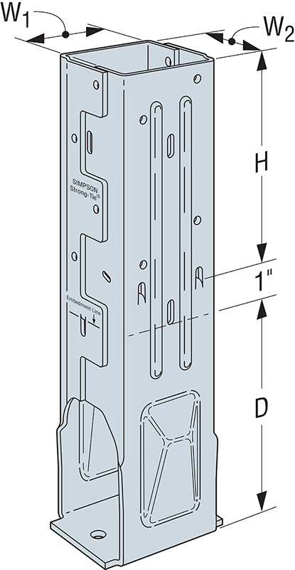
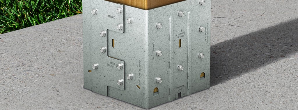
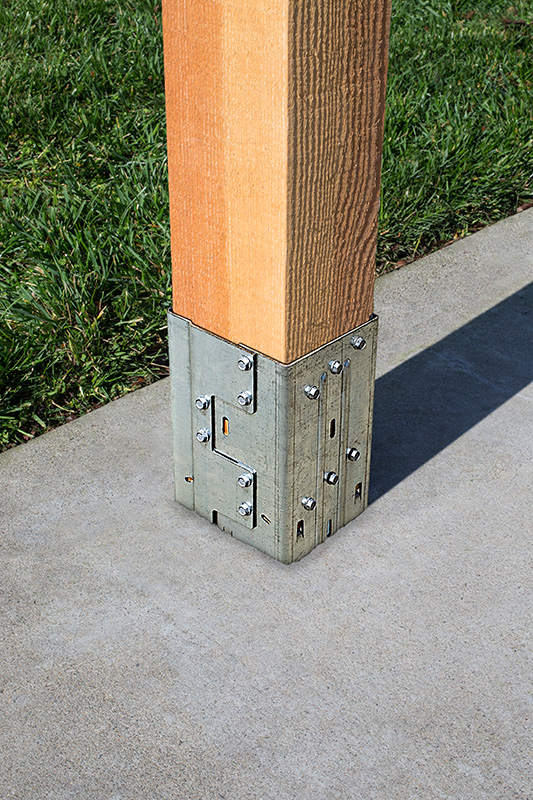
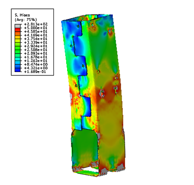
Lateral forces from wind and seismic loads on a structure are typically resisted by a lateral-force-resisting system. There are three main systems used for ordinary rectangular structures: (a) braced frames, (b) moment frames and (c) shearwalls. Moment frames resist lateral forces through bending in the frame members. Moment frames allow for open frames by eliminating the need for vertical bracing or knee bracing. Moment resistance or fixity at the column base is achieved by providing translational and rotational resistance. The new patent-pending Simpson Strong-Tie® MPBZ moment post base is specifically designed to provide moment resistance for columns and posts. An innovative overlapping sleeve design encapsulates the post, helping to resist rotation at its base.
The allowable loads we publish have what I call “triple backup.” This backup consists of Finite Element Analysis (FEA), code-compliant calculations and test data. Here are descriptions of what I mean by that.
Finite Element Analysis Confirmation
Once a preliminary design for the product is developed, FEA is performed to confirm that the product behaves as we expect it to in different load conditions. Several iterations are run to come up with the most efficient design.
Code-Compliance Calculations
Load calculations are prepared in accordance with the latest industry standards. The connector limit states are calculated for the wood-post-to-MPBZ connection and for MPBZ anchorage in concrete. Steel tensile strength is determined in accordance with ICC-ES AC398 and AISI S100-16. Wood connection strength is determined in accordance with ICC-ES AC398 and AC13. Fastener design is analyzed as per NDS. SDS screw values are analyzed using known allowable values per code report ESR-2236. The available moment capacity of the post base fastened to the wood member is calculated in accordance with the applicable bearing capacity of the post and lateral design strength of the fasteners per the NDS or ESR values. Concrete anchorage pull-out strength is determined in accordance with AC398.
Test Data Verification
The moment post base is tested for anchorage in both cracked and uncracked concrete in accordance with ICC-ES AC398.

The moment post base assembly is tested for connection strength in accordance with ICC-ES AC13.
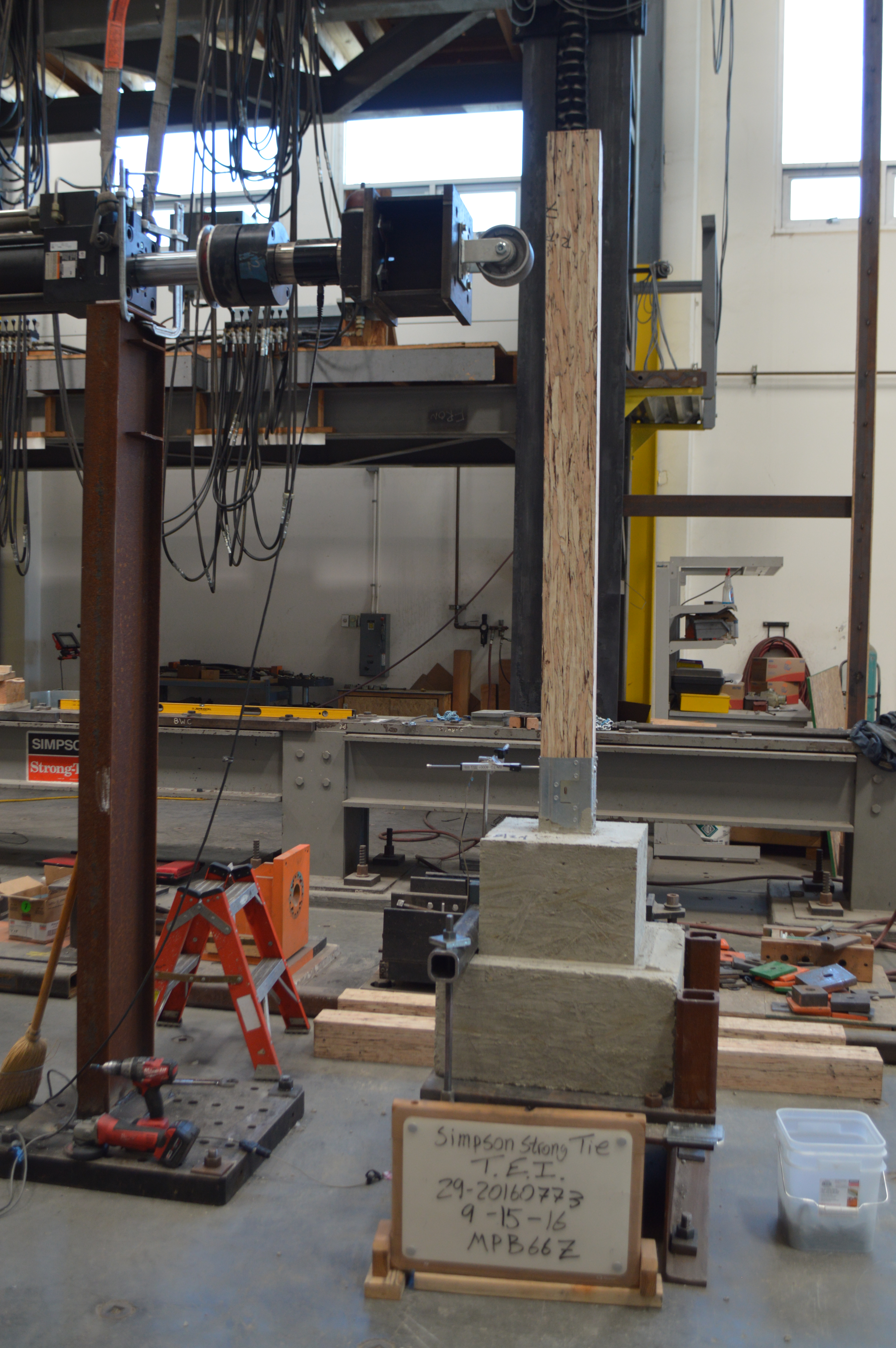
The assembly (post and MPBZ) is tested for various loading conditions: download, uplift and lateral load in both orthographic directions and moment. Applicable factor(s) of safety are applied, and the controlling load for each load condition is published in the Simpson Strong-Tie Wood Construction Connectors Catalog.
Now let’s take a look at a sign post base design example to see how the MPBZ data can be used.
Design Example:

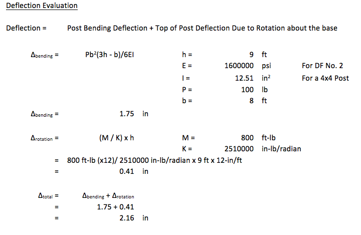
The MPB44Z is used to support a 9ʹ-tall 4×4 post with a 2ʹ x 2ʹ sign mounted at the top. The wind load acting on the surface of the sign is determined to be 100 lb. The MPB44Z is installed into concrete that is assumed to be cracked.
- The design lateral load due to wind at the MPB44Z is 100 lb.
- The design moment due to wind at the MPB44Z is (100 lb.) x (8 ft.) = 800 ft.-lb.
- The Allowable Loads for the MPB44Z are:
- Lateral (F1) = 1,280 lb.
- Moment (M) = 985 ft.-lb.
- Simultaneous Load Check:
- 800/985 + 100/1,280 = 0.89. This is less than 1.0 and is therefore acceptable.
We are very excited about our new MPBZ! We hope that this product will get you excited about your next open-structure design. Let us know your thoughts by providing comments here.
How do you Design Sole-Plate-To-Rim-Board Attachments?
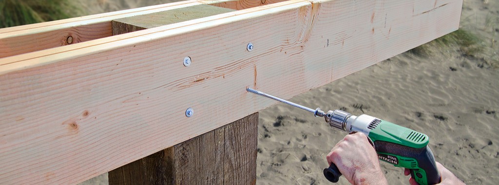
For many years, builders have struggled with the awkward sole-plate-to-rim-board attachment. They often install a few nails and call it good, resulting in a connection with significantly less capacity than needed. This connection is critical to ensure that seismic and wind loads are adequately transferred to the lateral-force-resisting system. With screws becoming much more common in construction, we saw an opportunity to address this problem.
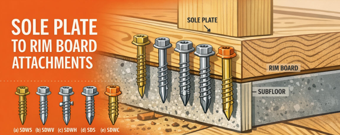
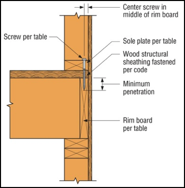
We offer a variety of structural wood screws that have shank diameters ranging from 0.135″ to 0.244″. They form our Strong-Drive® line of structural fasteners. The Simpson Strong-Tie® Strong-Drive SDWC Truss, SDWH Timber-Hex, SDWS Timber, SDWV Sole-to-Rim and SDS Heavy-Duty Connector structural wood screws as shown in Figure 1 can be used to attach sole plates to a rim board as shown in Figure 2. These screws provide structural integrity in the wall-to-floor connection.
The sole-to-rim connection is considered a dry service location. When the sole plate and the rim are both clean wood (not treated), then any of the screws can be used as long as they meet the design loads. However, if one or both members of the connection are treated with fire retardants or preservatives, then you must use the SDWS Timber screw, SDWH Timber-Hex screw or SDS Heavy-Duty Connector screw. The SDWS, SDWH and SDS screws all have corrosion-resistance ratings in their evaluation reports.
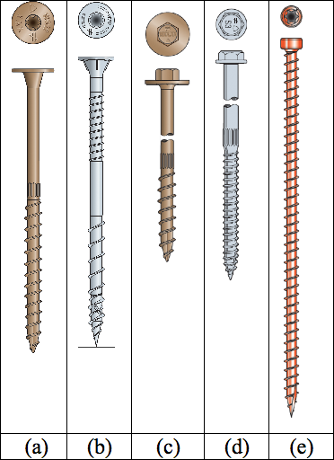
The Strong-Drive SDWV structural wood screw has the smallest diameter among these screws. The SDWV is 4″ long and has a 0.135″- diameter shank, and a large 0.400″-diameter ribbed-head with a deep six-lobe recess to provide clean countersinking. It is designed to be fast driving with very low torque. The Strong-Drive SDWS offers one of the larger diameters. It has a 0.220″-diameter shank and is offered in lengths of 4″, 5″ and 6″. It has a large 0.750″-diameter washer head which provides maximum bearing area. Longer screws allow designers to meet the minimum penetration requirement into a rim board, when the sole plate is a 3x or a double 2x member.
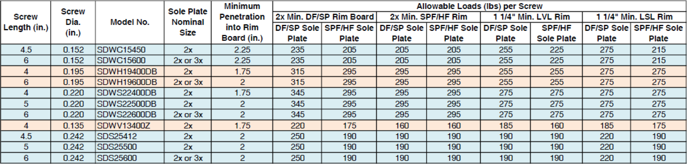
We have tested various combinations of sole plates, floor sheathing, and rim boards. Typical test assemblies were built and tested with two (2) Strong-Drive® screws spaced at either 3″ or 6″. Results were analyzed per ICC-ES AC233, “Acceptance Criteria for Alternate Dowel-type Threaded Fasteners.” The allowable loads listed in Table 1 are based on the average ultimate test load of at least 10 tests, divided by a safety factor of 5.0, and are rated per single fastener. The results of these tests can be found in the engineering letter L-F-SOLRMSCRW16.
The evaluated sole plates include southern pine (SP), Douglas fir-larch (DF), hem-fir (HF), and spruce-pine-fir (SPF) in single 2x, 3x or double 2x configurations. Floor sheathing thicknesses are allowed up to 1 1/8″ thick. Rim boards can be LVL or LSL structural composite lumber or DF, SP, HF or SPF sawn lumber. The load rating also assumes that the floor sheathing is fastened separately and per code.
See strongtie.com for evaluation report information if it is needed.
As a Designer, you can specify any of these Strong-Drive screws that fit your design requirements. Please visit our website and download L-F-SOLRMSCRW16 for more details.
Good luck!
Pile Construction Fasteners – New and Expanded Applications
The majority of Simpson Strong-Tie fasteners are used to secure small, solid-sawn lumber and engineered wood members. However, there is a segment in the construction world where large piles are the norm. Pile framing is common in piers along the coast, elevated houses along the beach, and docks and boardwalks.
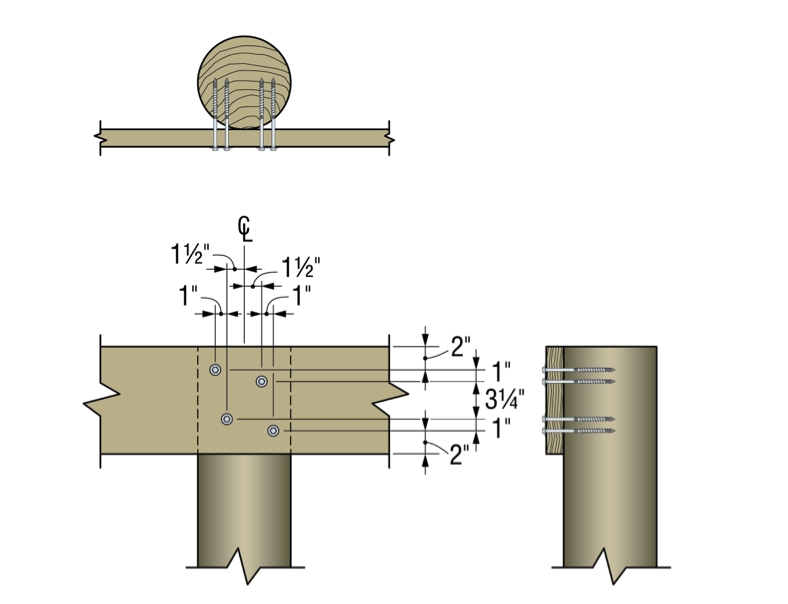
While the term “pile” is generic, the piles themselves are not generic. They come in both square and round shapes, as well as an array of sizes, and they vary greatly based on region. The most common pile sizes are 8 inches, 10 inches, and 12 inches, square and round, but they can be found in other sizes. The 8-inch and 10-inch round piles are usually supplied in their natural shape, while 12-inch round piles are often shaped to ensure a consistent diameter and straightness. All piles are preservative-treated.
Historically, the attachment of framing to piles has been done with bolts. This is a very labor-intensive method of construction, but for many years there was no viable fastener alternative. Two years ago, however, Simpson Strong-Tie introduced a new screw, the Strong-Drive® SDWH Timber-Hex HDG screw (SDWH27G), specifically designed for pile- framing construction needs. It can be installed without predrilling and is hot-dip galvanized (ASTM A153, Class C) for exterior applications.

Simpson Strong-Tie tested a number of different pile-framing connections that can be made with the SDWH27G screw. This blog post will highlight some of the tested connections. More information can be found in the following three documents on our website:
- The flier for the SDWH Timber-Hex HDG screw: F-FSDWHHDG14 found here.
- The engineering letter for Square Piles found here.
- The engineering letter for Round Piles found here.
The flier provides product information, and the engineering letters include dimensional details for common pile-framing connections that were tested.
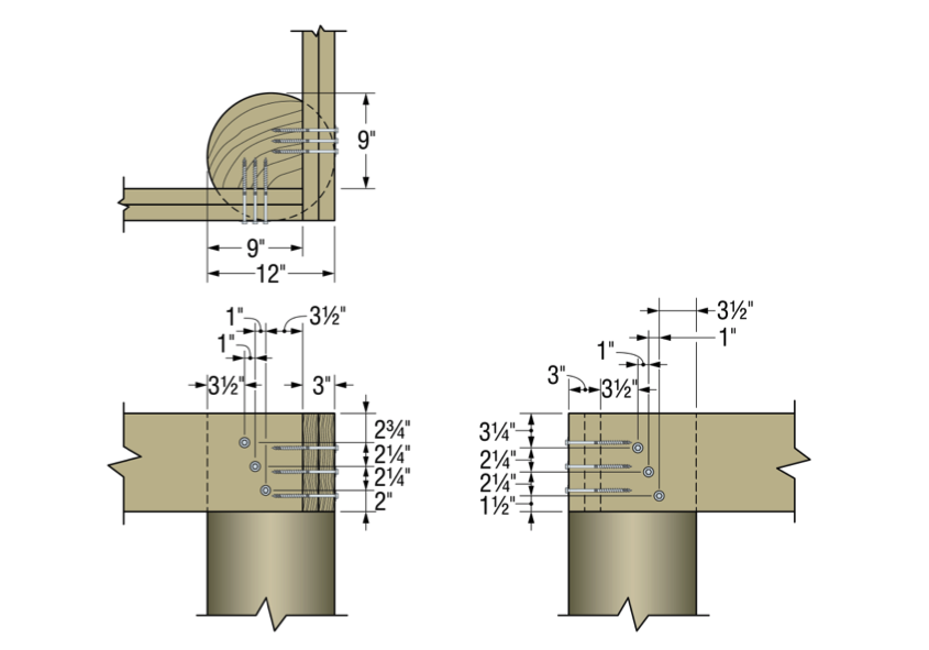
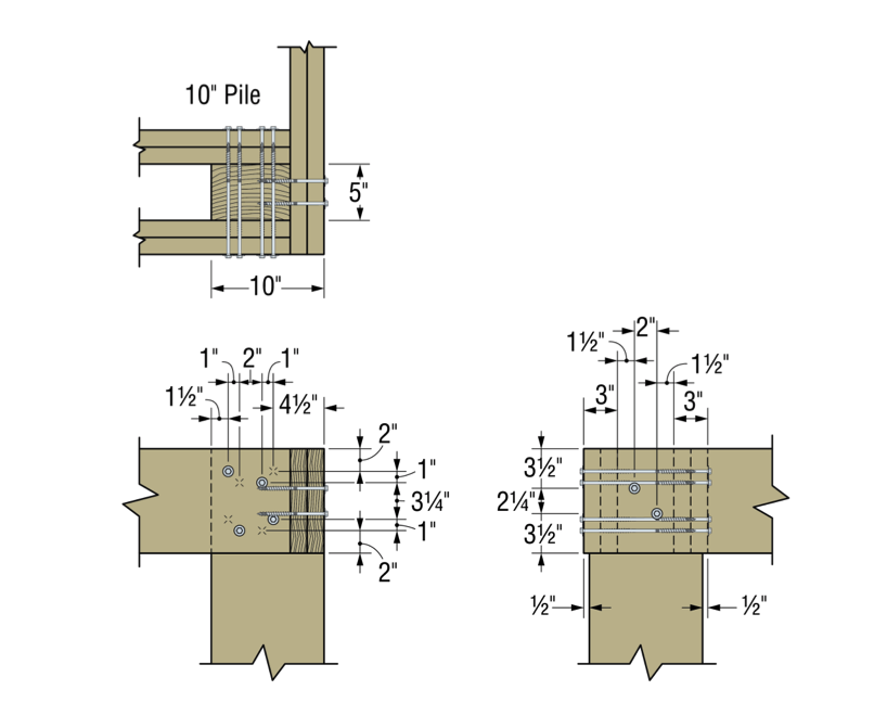
Piles are typically notched or coped to receive a horizontal framing member called a “stringer.” The coped shoulder provides bearing for the stringer and serves as a means of transferring gravity load to the pile. The SDWH27G can be used to fasten framing to coped and non-coped round and square piles.
The connections that we tested can be put into four general groups that include both round and square piles:
- Two-side framing on coped and non-coped piles
- One–side framing on coped and non-coped piles
- Corner framing on coped piles
- Bracing connections
Additionally, the testing program included four different framing materials in several thicknesses and depths:
- Glulam
- Parallam
- Sawn lumber
- LSL/LVL
The total testing program included more than 50 connection conditions that represented pile shape and size, framing material and thickness and framing orientation and details. We assigned allowable uplift and lateral properties to the tested connections using the analysis methods of ICC-ES AC13. Figures 2 and 3 show some of the tested assemblies.
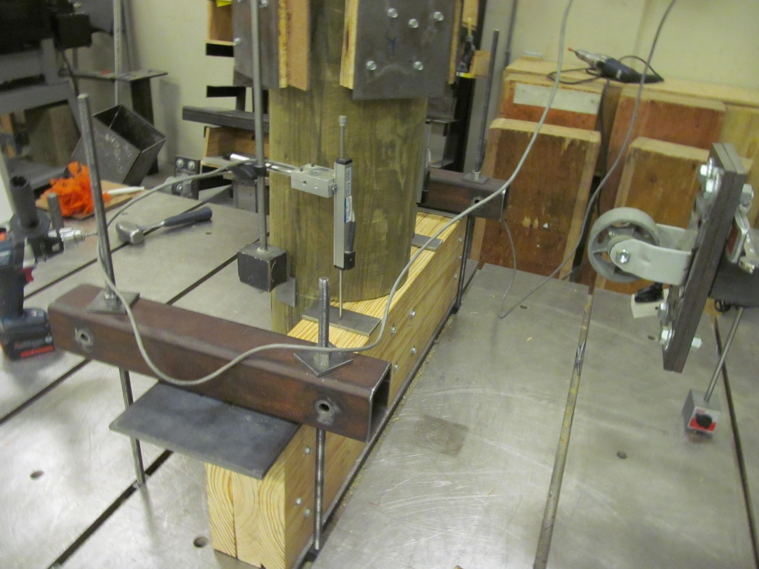
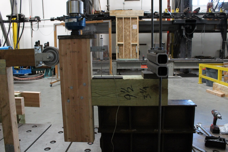
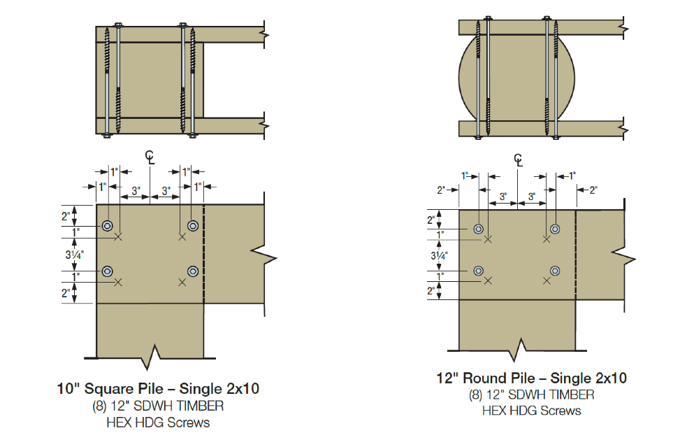
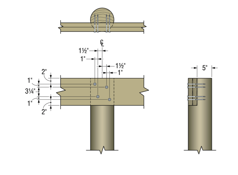
Figures 4 through 9 illustrate some of the connections and details that are presented in the flier and engineering letters.
Some elements of practice are important to the design of pile-framing connections. Some of the basic practices include:
- For coped connections, the coped section shall not be more than 50% of the cross-section.
- For coped connections, the coped shoulder should be as wide as the framing member(s).
- Fastener spacing is critical to the capacity of the connection.
- When installing fasteners from two directions, lay out the fasteners so that they do not intersect.
In many cases, pile-framing connections use angled braces for extra lateral support. The SDWH27G can be used in these cases too.

In the flier and engineering letters previously referenced, you will find allowable loads and specific fastener specifications for many combinations of stringer and pile types and sizes.
What have you seen in your area? Let us know – perhaps we can add your conditions to our list.

New LSSJ Hanger Strengthens Jack Rafter Connections
When our company is considering a new or improved product, we like to start out by talking to our customers first. That’s what we did recently with a connector improvement project for attaching jack rafter hangers in roof framing – and we got lots of feedback!
We heard from installers that they really wanted a hanger that could be easily adjusted in the field for different slopes and skews. We were asked whether we could design a hanger that could be installed after the rafters were already tacked into place to support construction sequencing and retrofit applications. Also, having a hanger that could be installed from one side was a popular time-saving request.
Our Engineering innovation team took all this feedback and closely evaluated our current selection of hangers. After much consideration, the team decided that rather than adapt one of our existing hangers, they would try to come up with an all-new design that would satisfy our customers’ most pressing needs.
After months of designing and testing prototypes in the lab and in field trials, the answer was yes. The result is our new LSSJ field-adjustable jack hanger. It’s an innovative field-slopeable and field-skewable hanger that features a versatile hinged seat. This new design allows it to be adjusted to typical rafter slopes, with a max slope of 12:12 up or down.
What is a jack hanger and why does it provide a better connection than nails alone?
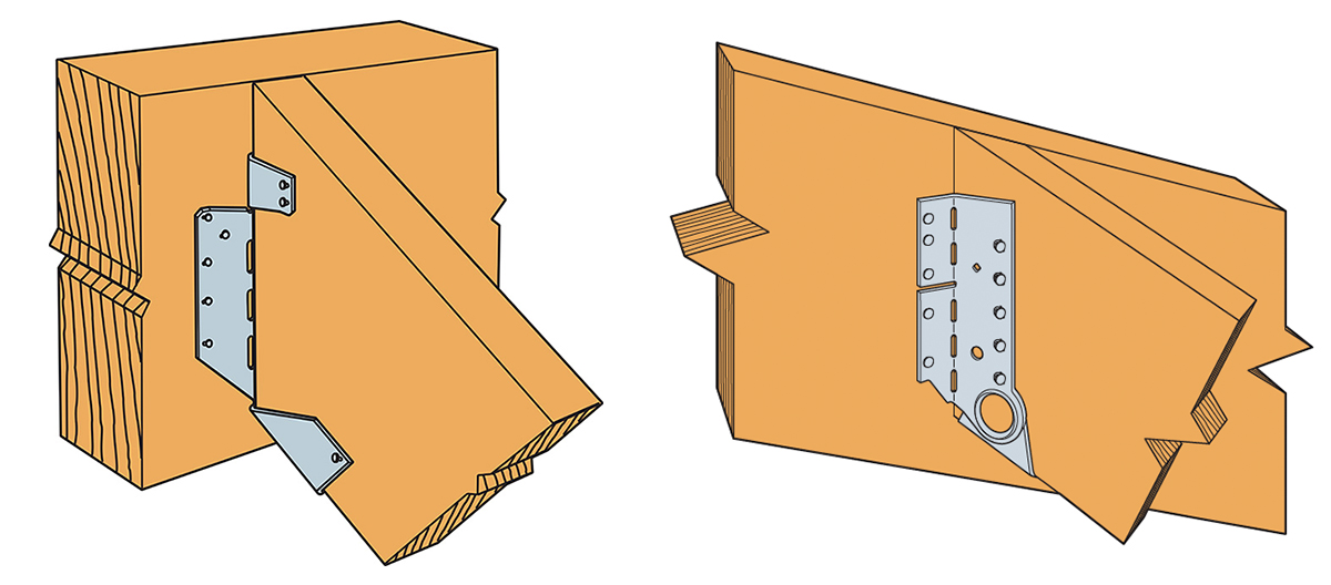
There are two basic types of wood roof construction: framed roof construction (stick framing) as shown above, and truss assembly. The main difference is that stick assembly takes place onsite, while trusses are prefabricated and ready to place. In the United States, the number of truss-built roofs versus stick-frame roofs is about two to one. The LSSJ jack hanger is used for stick-frame construction and provides a connection between the jack rafter to either the hip rafter or the valley rafter as shown below.

Connecting a 2X jack rafter to a hip is hardly new. The hardest thing is making a good compound miter cut – something an experienced framer can figure out (and most engineers marvel at). In many parts of the country, these are simply face-nailed into place. Often there isn’t a lot of engineering that goes into that connection. However, a closer look raises a couple of questions.
Random Nail Placement
Where exactly are those nails going? When there’s no seat support for the rafter, the allowable shear is reduced per the NDS depending on where the lowest nail on the rafter is. This is based on the split that develops at the lowest fastener. The LSSJ provides a partial seat which not only meets the bearing requirement of section R802.6 of the IRC but also delays the type of splitting found in a nailed-only connection.
Consistent Nail Placement
The LSSJ conforms to the bottom of the jack rafter slope and ensures consistent nail placement on both the rafter and the hip. Consistent nail placement promotes consistent performance based on testing (or as consistent as wood gets)! The highest nail on the hip is located near the neutral axis if the hip is one size deeper than the rafter. This assures that not all the load is focused at the bottom of the hip.
A Closer Look at the LSSJ Jack Hanger
Some of our customers may be familiar with our current product, the LSSU, which is used for the same connection. Here’s a closer look at the improvements that the LSSJ offers.
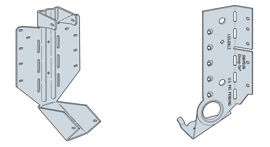

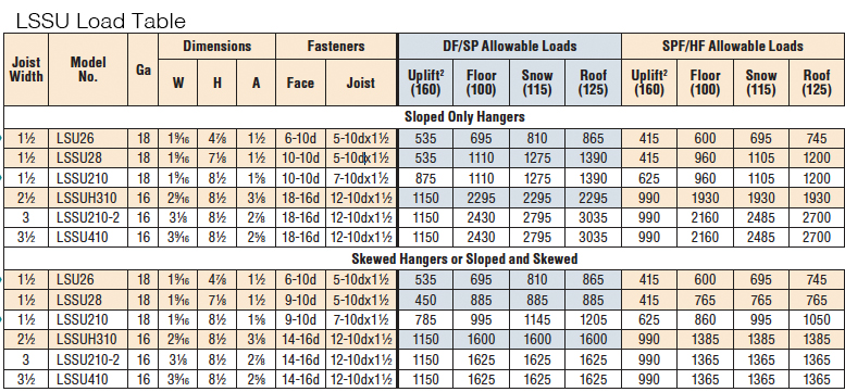
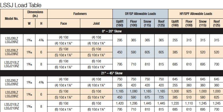
You can see the differences and improvements just by looking at these hangers, installations and load tables. Here’s a different way of showing the advances and benefits of the LSSJ:

One of the greatest improvements is the fact that there are fewer nails to install in the LSSJ, and the loads are very similar if not better.
In addition to the LSSJ, Simpson Strong-Tie offers a full line of connectors for wood-framed sloped roofs, including:
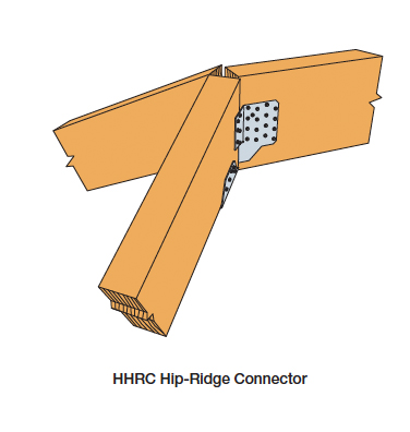


We look forward to hearing from you about our newest innovation. For more information about the LSSJ hanger, please see strongtie.com.

Cold-Formed Steel Curtain-Wall Systems
In August 2012, Simpson Strong-Tie launched a comprehensive, innovative solution for curtain-wall framing. Our lead engineer for developing our line of connectors for curtain-wall construction explains the purpose of the curtain wall with the illustrations below.
 First, curtain walls are not what you put up if you shared a room with your brother and sister when you were growing up. When I first learned about the use of cold-formed steel curtain walls, I laughed and thought: “Gosh, how useful this would be for someone growing up with 5 siblings in one bedroom!” I have always enjoyed the sense of humor that our engineers use to help explain technical topics.
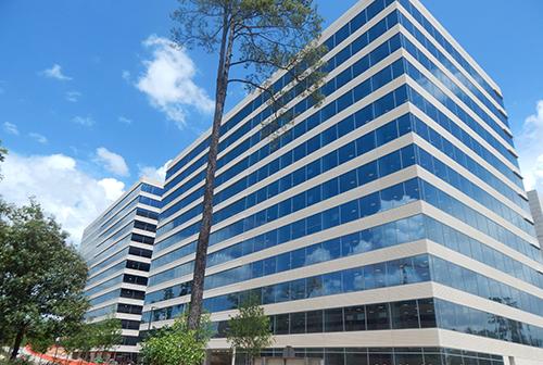
Curtain walls can be described as exterior building walls with the primary purpose of protecting the interior building against the exterior weather and natural phenomena such as sun exposure, temperature changes, earthquakes, rain and wind.
To put it in structural terms, a curtain-wall system consists of non-load-bearing exterior walls that must still carry their own weight. Curtain walls are not part of the primary structural framing for the building, but they typically rely on the primary structural framing for support. Additionally, curtain walls receive wind and seismic loads and transfer these forces to the primary building structure.
Types of Curtain Walls
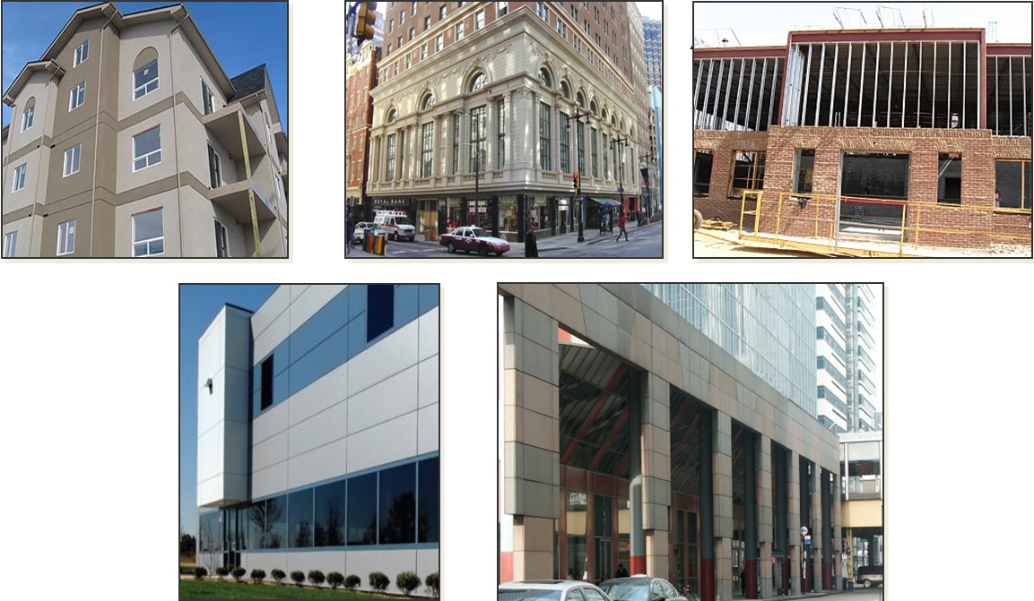
Glass and cladding curtain walls make up two basic types of curtain-wall systems. Glass curtain-wall systems are usually designed using aluminum-framed walls with in-fills of glass. The cladding curtain wall is a system with back-up framing that is covered in some type of cladding material. The cladding curtain-wall system is the type in which Simpson Strong-Tie products can be used.
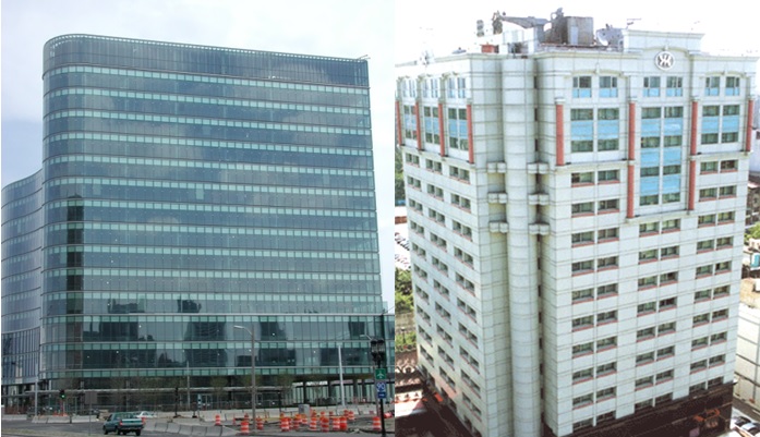 The back-up framing is the structural element of the curtain-wall system. It is typically constructed with cold-formed steel studs ranging from 31/2″ to 8″ deep, in 33 mil (20 ga.) to 97 mil (12 ga.) steel thicknesses. The framing studs are typically spaced at 16″or 24″ on center. There are many different types of cladding materials. They include, but are not limited to, exterior insulation finish systems (EIFS), glass-fiber-reinforced concrete (GFRC), bricks, metal panels and stone panels.
 Deflection
One essential function of the curtain wall is to allow for relative movement between the curtain-wall system and the main building structure. At first, it was not obvious to me why making this allowance was necessary, but our product development team creatively explained some of the reasons why this is an important must-have feature for curtain walls.
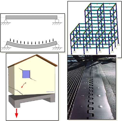 First, the primary building will move up and down as it is loaded and unloaded by the live-load occupancy, similar to beam live-load deflections.
Second, the structure sways and has torsional displacement due to movement from lateral wind or seismic loads.
Third, concrete structures typically encounter creep and shrinkage, and there may be foundation differential settlement or soil compression from high-gravity loads.
Lastly, the temperature differential may cause the building elements to expand and contract, which, again, can result in relative movement between structural elements. This is similar to a bridge’s steel plate expansion joint system.
And if you are a curious designer like me, you probably wonder why the relative vertical moment is so significant in engineering design.
One key reason is to ensure that the curtain walls do not collect gravity loads from the building, so as to prevent overloading and possible failure of the stud framing. In addition, a well-designed curtain-wall system needs to retain the primary structural load path as intended by the building designer.
The other reason is to protect the cladding of the building. If you remember earlier, the cladding material may be marble, granite or natural stones that are often very expensive and heavy. In some cases, the cladding can be one of the most expensive systems in a building. And there are times when it’s much more cost-effective to design for relative movement than it is to over-design structural framing to address the stringent deflection requirements.
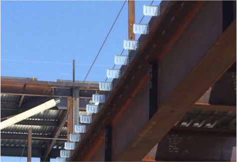
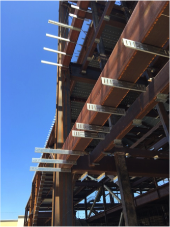
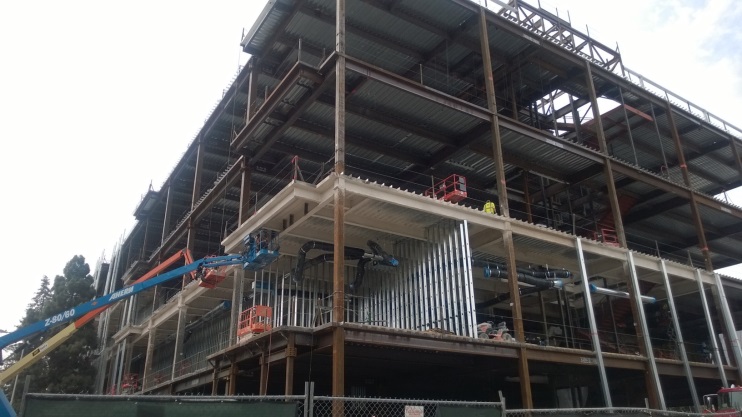
Construction Type
Bypass framing is a term that is often used in curtain-wall construction. In this system, the metal studs bypass the floor and hang off the outside edges of the building. You can see from the illustration how the studs run past, or bypass, the edge of the slab. In this case, the studs are supported vertically on the foundation at the bottom, and then run continuously past multiple floor levels.
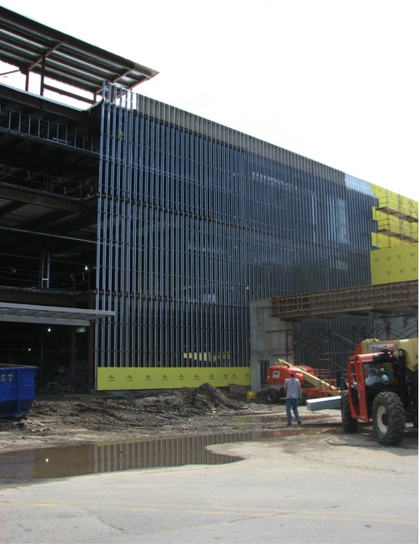
In steel construction, concrete fill over metal deck is typically constructed with a heavy-gauge bent plate or structural angle. Connectors can attach directly to the steel angle or the web of an edge beam.
It may seem that this type of construction is too complex and requires great efforts to detail the many connections needed to hang the curtain wall off the outside of the building. So what are the compelling reasons to choose bypass framing construction?
Bypass framing can accommodate flexibility for the architect. In another words, the bypass configuration easily allows architects to create reveals, set-backs and other architectural features. Plus, there are fewer joints to detail for movement when stud length can run continuously for several floors. Another benefit is that the exterior finish can also be installed on a curtain-wall system with a tighter tolerance than the edge of the structure.
One other special bypass framing type is known as ribbon window or spandrel framing. Ribbon windows are a series of windows set side by side to form a continuous band horizontally across a façade. The vertical deflection for this type of bypass framing is typically accommodated at the window head. This type of bypass usually works well for panelized construction.
Another common curtain-wall system is infill framing, where the studs run from the top of one floor to the underside of the floor above. Sometimes it’s a challenge to attach bypass framing to the edge of thin concrete slabs. In the following illustration, deflection is designed at the top track of wall panels.
 In Part 2 of this blog post series, I will provide more details about how we have innovated products to be used for this application, plus a more comprehensive post about the products we offer and how they are typically used.
In the meantime, you can check out our product offering. Our recent SC slide-clip and FC fixed-clip connectors are designed for high-seismic areas.
I would like to invite you to comment and provide feedback on this topic and tell us whether you’ve had any experience working with a Designer on a CFS curtain-wall project. If you are a Designer who specializes in this discipline, how are you designing curtain-wall systems for seismic forces?

How to Pick a Connector Series – Truss Hangers
In our second blog in the “How to Pick a Connector Series,” Randy Shackelford discussed the various considerations involved in selecting a joist hanger. So why is this blog post about truss hangers? A hanger is a hanger, right? Before I moved into the Engineering Department at Simpson Strong-Tie, I was the product manager for our Plated Truss product line. I can assure you that there is a bit more that goes into the selection (and design) of a truss hanger than does into selecting a joist hanger!
Of course, all of the considerations that were covered in the joist hanger blog apply to truss hangers as well. This blog post is going to discuss some additional considerations that come into play in selecting a hanger for a truss rather than a joist, and how some hangers have features designed especially for trusses.
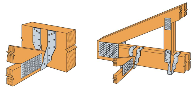
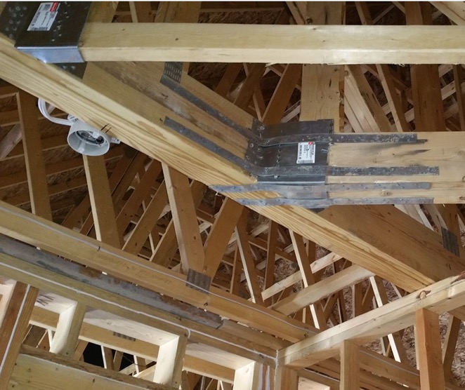
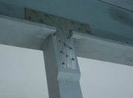
The first (and most obvious) truss-specific consideration is the presence of webs. Because of truss webs, top-flange hangers are not as conducive to truss applications as they are to joist applications. A better alternative for trusses is an adjustable-strap hanger that can be installed as a top-flange hanger or face-mount hanger. Take the THA29, for example, Simpson’s first hanger developed specifically for the truss industry (circa 1984). It can accommodate different girder bottom chord depths, which eliminates the need for multiple SKUs, and the straps can be field-formed over the top of the girder bottom chord to reduce the number of fasteners (just like top-flange hangers). When a web member is in the way of the top-flange installation method, the straps can be attached vertically to the web in a face-mount installation instead.
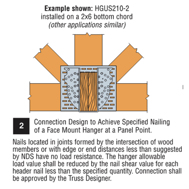
What if the web at that location isn’t vertical? You can still install the strap onto the web, but if any nails land in the joint lines formed by the intersection of the wood members, they cannot be considered effective. Therefore, the hanger allowable load may need to be reduced to account for ineffective header nails. This alternative installation is acceptable for any face-mount hanger located at a panel point as shown in our catalog (see detail below).
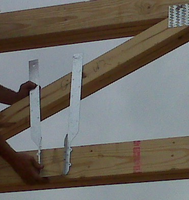
Although very versatile, not all adjustable-strap hangers can be installed on all sizes of bottom chords. Our catalog specifies a C-dimension for these hangers, which corresponds to the height of the side-nailing flanges. If that dimension exceeds the height of the bottom chord, then the straps cannot be field-formed as needed for the top-flange installation. And if the hanger isn’t located at a panel point, nailing the straps to any diagonal web that the straps can reach (see photo below) is not an acceptable option!
Another unique consideration that goes into the selection of a truss hanger is the heel height of the carried truss. A truss with a short heel height installed into a tall hanger will likely leave air (or “daylight,” as I call it) behind a lot of the nail holes running up the side flanges. When nail holes in a hanger have air behind them instead of wood, this equates to a reduction in hanger capacity. So when the carried truss has a heel height that is much less than the depth of the carrying member (and the hanger), it is important to use the appropriate hanger capacity for that condition and not overestimate the hanger’s capacity. Refer to our technical bulletin T-REDHEEL for allowable loads for reduced heel height conditions.

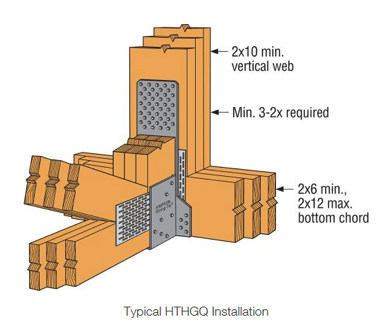
Because trusses are capable of carrying a lot of load – and producing large reactions – hangers for truss applications often require larger capacities than joist hangers. Unfortunately, there is only so much capacity that can be achieved from a hanger that fits entirely onto a girder truss bottom chord. Therefore, in order to use our highest load-rated truss hangers, a properly located vertical web is required, and the web must be wide enough for the hanger’s required face fasteners and minimum edge distances. The more capacity that is required, the more fasteners it takes, and the wider the vertical web must be. Our highest-load-rated truss hanger that installs with screws is the HTHGQ. It has a maximum download capacity of 20,735 lb., but it requires a minimum 2×10 vertical web. The THGQ/THGQH series can be installed onto as small as a 2×6 web, but the maximum possible capacity on a 2×6 web is 9,140 lb.
In addition to high-capacity hangers, truss applications often require high-capacity skewed hangers. When selecting skewed hangers, it’s important to realize that hangers with custom skew options usually have a reduction that must be applied to the hanger’s 90-degree capacity. Another important factor that is sometimes overlooked in the selection of skewed hangers is whether the carried member is square-cut or bevel-cut. When the member is square cut – as in the case of trusses – not only does this typically result in a greater reduction in capacity, but some skewed hangers cannot be used at all with square-cut members. For example, the fastener holes on the side flange may not be located far enough away from the header to accommodate square-cut members. See the photo below for an example of what can happen if a skewed hanger that is intended for a bevel-cut member is used for a truss.

As discussed in the previous hanger blog, face-mount hangers offer the advantage of being installed after the joist (or truss) is installed. What if the truss is installed prior to the hanger and a gap exists between the truss and the carrying member? In that case, the best option may be to select a truss hanger that was designed with this type of installation tolerance in mind, the HTU hanger. Other face-mount truss hangers that use double-shear nailing are great when gaps are limited to ⅛” or less, but their capacities take a pretty large hit when the gap exceeds ⅛” (see our previous blog Minding the Gap in Hangers for more information). The HTU was designed to give an allowable load for up to a ½” gap between the end of the truss and the carrying member. In addition, it has built-in nailing options to accommodate short heel heights even in the taller models – definitely a truss hanger!

Finally, there is one more thing to consider when selecting a face-mount hanger for a truss application, which relates to how tall the carrying member is compared to the hanger. Assuming the bottom of the hanger will be installed flush with the bottom of the girder bottom chord, a hanger that is much shorter than the bottom chord will induce tension perpendicular to the grain in the chord. Due to wood’s inherent weakness in perpendicular-to-grain tension, a hanger that is too short may limit the amount of load that can be transferred– to something less than the hanger’s published allowable load. Therefore, it isn’t enough to check whether the hanger fits on the bottom chord; the hanger must also cover enough depth of the chord to effectively transfer the load (or else the allowable hanger load may need to be reduced to the member’s allowable cross-grain tension limit).
Cross-grain tension is not a truss-specific issue, but because it is an explicit design provision in the truss design standard (TPI 1), it is a necessary consideration to mention in a discussion about truss hanger selection. In fact, proper detailing for cross-grain tension in different wood applications could be a future topic in and of itself.
Add to all this the specialty truss hangers that can carry two, three, four, and even five trusses framing into one location, and it is no wonder that there is an entire section in our catalog that is dedicated to truss hangers. Are there any other truss hanger needs that you would like to discuss? Please let us know in the comments below!

Can Decorative Hardware Add Structural Strength?
At Simpson Strong-Tie, we really try to listen to our customers. Our products are developed with your needs in mind.
Last year, at my daughter’s college orientation, I found myself in an interesting conversation with one of the other parents. It turned out that he owns a deck-building company. When he found out that I’m an engineer at Simpson Strong-Tie, his first question was “why don’t you guys make some nice-looking connections that I can use on my decks?”
I had to choke back a laugh because that’s exactly what I was working on at the time. What he didn’t mention (but we knew he also needed) were connectors that are fast to install, suitable for outdoor use and structurally rated for engineered designs. We also knew code approval was critical to help building departments approve the designs.
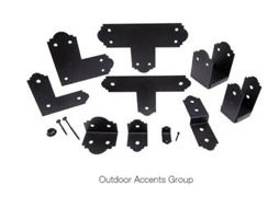
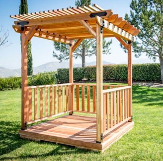
The Outdoor Accents® connectors we designed include some basic T’s, L’s, angles and post bases with a nice architectural feature of decorative edges from our Mission Collection®. The steel has our ZMAX® (G185) galvanizing (which is twice as heavy as our standard G90) to resist corrosion and a black powder-coat finish for aesthetics.
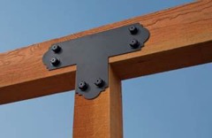
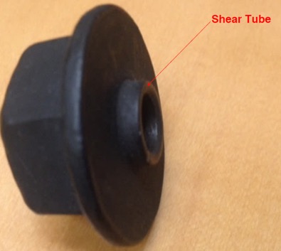
But the real innovation is in the fastener. Architectural connectors and big bolts go hand in hand, but big bolts are expensive, time consuming and often structurally unnecessary. To solve the installation issue, we designed a decorative washer that looks like a washer and nut and perfectly fits our SDWS22DBB Structural Wood screw.
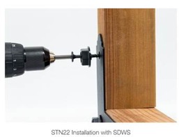
We named it the shear tube nut (STN) because the extended tube increases the shear area in contact with the connector.
Together with the SDWS22DBB screw, this solution looks like a bolted connection but installs with the speed and ease of a self-tapping screw. Structurally as well, the hardware is comparable to a bolted connection with a shear capacity of 470 lb. per fastener when used with metal side plates, i.e., connectors.1 The solution has also been tested and load rated for use directly on wood, so it can be used for a variety of other connections such as joining multi-ply beams, knee braces, etc.
In order to be code approved, the SDWS22DBB screws were tested with and without the STN in both wood-to-wood and metal-to-wood per AC233 Acceptance Criteria for Alternate Dowel-Type Threaded Fasteners. The connectors and fasteners, including STN, were tested as assemblies per ASTM D7147. Code agency reviewers quickly saw the benefits of the design and issued evaluation reports verifying the loads. The Outdoor Accents® connectors and SDWS22DBB screws are recognized under IAPMO UES ER-280 and ER-192, respectively. The smaller APA21 angle uses our new SD10112DBB screw, which is listed in ICC-ES ESR-3046.
My deck-builder friend will be pleased to see the new connectors are now available at select Home Depot stores.
I can’t wait to see what he thinks of them and to get his ideas for the next big project. How about you? What would you build with these new architectural products? Let us know in the comments below.
- Ref. IAPMO UES ER-192 Table 6A steel side member DF = 470 lb.; 2015 NDS Table 12B 3 1/2″ main member, 1/2″ bolt, DF perpendicular-to-grain = 510.
Outdoor Accents®
Add Beauty and Strength to Your Custom Outdoor Living Structures.


Designing Gable End Overhangs
It seems that each major hurricane tends to teach those of us in the construction industry some lesson. With Hurricane Andrew, the lessons were the importance of protection from windborne debris, and the importance of proper construction of gable end overhangs.
There are two main areas where gable ends can fail.