Structural Engineering Blog: One-Year Anniversary

Photo credit: Thinkstock.

This month marks the one-year anniversary of the Simpson Strong-Tie® Structural Engineering Blog! To celebrate, we are holding a contest for our blog readers and sharing a few interesting statistics about the blog, along with our Top 5 Blog Posts from April 2012 to today.

Everyone who posts a comment or subscribes to receive email notifications to the blog (new subscribers only) from now until April 30, 2013 will be entered to win one of five Prize Packs. The Prize Pack consists of:

The contest is open to U.S. and Canadian residents (except Quebec) only. One entry per person. Five entries will be randomly selected to receive a Prize Pack. You can read the Official Rules here.

Continue Reading

Overview of Code-Plus Programs

We all know that the purpose of a building code is to provide minimum requirements for the health, safety, and welfare of the occupants of buildings built under that code.  But what if the owner wants a building that will perform better than the absolute minimum allowed by the code?Continue Reading

Is Designing with Wood Easy?

In college, I spent some of my free time either attending seminars or reading about high profile structural engineering projects. These projects tend to be noteworthy due to their massive scale or their use of innovative construction technologies (often both). Taipei 101 is 508 meters tall, and used to be the tallest building in the world. The Burj Khalifa has surpassed it as not only the tallest building in the world, but as the tallest manmade structure at 828 meters.

 I never thought I would design the world’s tallest buildings, but I did think it would be cool to work on some mid-rises. I never did. My design firm didn’t do that type of work – which looking back, was a good thing for me. We worked on a lot of everything, including commercial, industrial, multi-family and mixed-used projects. The variety of projects meant designing with all the major building materials, including concrete, steel, masonry, and wood. Reviewing my project portfolio and thinking about what was really satisfying to work on, the projects that stand out most were wood-framed.

Continue Reading

2012 Autodesk University

Autodesk University is an annual conference focused on keeping the design community up to date on the latest innovations, trends and technologies in design, drafting and visualization. Last year, Autodesk University was held in Las Vegas the week after Thanksgiving. Sadly, events always seem to conspire to prevent me from going to Vegas, but Simpson Strong-Tie was well represented by Frank Ding, our Engineering Analysis & Technical Computing Manager.

It was an exciting time attending my first Autodesk University in 2012. I have been to so many technical conferences during my professional career, but this one was quite different in scale, and the sheer size of it just blew me away. There were more than 8,000 attendees from 102 countries, more than 750 classes offered, and 163 exhibitors. I was impressed by the organization of such a large event, along with the online and mobile apps provided to help attendees manage their conference schedules.Continue Reading

Open Front Structure Wind Pressure Design

We received a request from Martin H., one of our blog readers, to discuss the method for determining roof wind pressures on an open front agricultural building. The inquiry was regarding clarification on analyzing the roof pressure when a combined external and interior pressure exists and whether these are additive.

Wind Pressure Figure

As can be seen in the above illustrations, the net design pressure on the roof is the sum of the uplift on the exterior surface and the uplift on the interior surface from any internal pressure. ASCE 7 provides a method for determining this pressure. Specifically, ASCE 7-10 will be used for the remainder of this post. Assuming the three remaining sides of the open front structure are walls without openings, the building will be classified as partially enclosed by the definitions of Section 26.2.

ASCE 7-10 provides for two methods for determining the Main Wind Force Resisting System (MWFRS) wind loads for partially enclosed buildings, the Directional Procedure in Chapter 27, and the Envelope Procedure in Chapter 28.

When using the Directional Procedure, the net wind load is calculated using the following equation:

P = qGCp – qi(GCpi)

When using the Envelope Procedure, the net wind load is calculated using the following equation:

 P = qh[(GCpf) – (GCpi)]  

In each of these equations, the first portion determines the pressure on the exterior surface, and the second portion determines the pressure on the interior surface. So the variable for calculating the internal pressure is the internal pressure coefficient GCpi.

The internal pressure coefficient is provided in Table 26.11-1 based on three different categories of building enclosure.

Enclosure Classification

(GCpi)

Open Buildings

0.00

Partially Enclosed Buildings

+0.55

-0.55

Enclosed Buildings

+0.18

-0.18

Table 26.11-1

In the case of an open front structure, it is assumed that the partially enclosed internal pressure coefficient must be used. This coefficient is 3x greater than when the building envelope is classified as enclosed. Use of this higher coefficient in the design will account for the interior pressure on the underside of the roof combined with the exterior pressure.

MWFRS versus C&C

Another somewhat related question: to what level loads should the roof anchorage forces be calculated, MWFRS or C&C (Component and Cladding)? I have often been asked this question, and wrote a Technical Note published by CFSEI (Cold-Formed Steel Engineers Institute) in July 2009.

What are your thoughts?

– Sam

Code Reports: Uniform Application of Code Intent in a Diverse Environment

Woodworks invited me to do a presentation on Testing and Evaluation of Products for Wood-framed Construction, and I found you can’t really talk about testing without talking about the test standards and criteria used in product evaluations. Usually the goal in testing to these standards is to show compliance with the intent of the building code and have the product listed in a code report.

Why not just follow the code?

Innovative architectural and structural building products not addressed by the building code are in every building. Revisions to the building code are considered on a three-year cycle and some standards are on a five-year cycle. Sometimes it may take several cycles to address a new building product.

Continue Reading

Lab Statistics – How Much Wood?

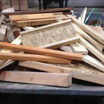
Wood for testing
Wood for testing

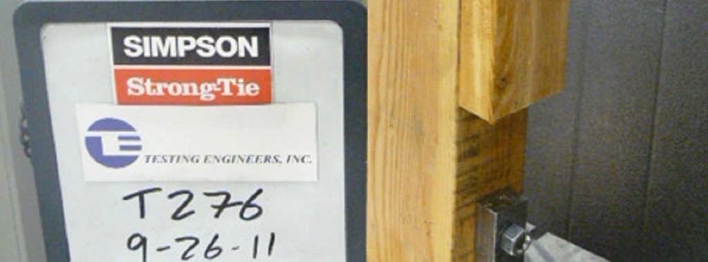
Like many people with desk jobs, I just have to get up and walk around every once in a while. Most of my walks are through our connector test lab at our home office in Pleasanton, California. The lab technicians install a lot of products for testing, so in addition to stretching my legs, I like to quiz them for ideas on things we can do to make installation faster and easier for our products.

Discarded wood from testing

During one of my walks this week, a lab technician was finishing up a rather extensive test setup that consumed a large quantity of lumber, screws, and truss plates. I asked him how it was going and he commented, “Testing isn’t exactly environmentally friendly, is it?”

Before I could even respond, he added, “I guess that’s just part of the price of building safer buildings.” I like the way he thinks.

Continue Reading

So, What's Behind A Screw's Allowable Load?

This is Part 2 of a four-part series I’ll be doing on how connectors, fasteners, anchors and cold-formed steel systems are load rated. Read Part 1 and Part 1A.
These loads just can’t be right! Occasionally, I get this statement from engineers. This happens when they have been specifying commodity fasteners based on NDS load values and they get their first look at our higher screw values. Then the call comes in. They want to talk to someone to confirm what they are seeing is correct. I assure them the loads are right and give them this brief overview of how we got here:
Our first structural screw, the Simpson Strong-Tie(R) Strong-Drive(R) SDS, was originally load rated by plugging the bending yield strength and diameter into the NDS yield limit equations and using the load value from the governing failure mode. As later editions of the NDS modified the calculations and we did more testing, we found that the tested ultimate load of the SDS screw could be as much as ten times greater than the allowable load generated from the NDS equations.
Continue Reading

So, What’s Behind A Screw’s Allowable Load?

This is Part 2 of a four-part series I’ll be doing on how connectors, fasteners, anchors and cold-formed steel systems are load rated. Read Part 1 and Part 1A.

These loads just can’t be right! Occasionally, I get this statement from engineers. This happens when they have been specifying commodity fasteners based on NDS load values and they get their first look at our higher screw values. Then the call comes in. They want to talk to someone to confirm what they are seeing is correct. I assure them the loads are right and give them this brief overview of how we got here:

Our first structural screw, the Simpson Strong-Tie(R) Strong-Drive(R) SDS, was originally load rated by plugging the bending yield strength and diameter into the NDS yield limit equations and using the load value from the governing failure mode. As later editions of the NDS modified the calculations and we did more testing, we found that the tested ultimate load of the SDS screw could be as much as ten times greater than the allowable load generated from the NDS equations.

Continue Reading

Soft-Story Retrofits

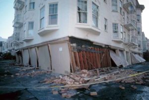
In February 2007 I had the opportunity to volunteer for a Soft-Story Sidewalk Survey for the San Francisco Department of Building Inspection. The purpose of the survey was to inventory buildings in San Francisco that appeared superficially to have soft or weak first stories. The volunteers were given a list of addresses to review and we recorded if the building was more than three stories tall, had five or more dwellings, and estimated what percentage of the ground level had openings in the walls. No structural analysis going on, just counting stories, mailboxes, doors and windows.

San Francisco soft-story structure. Photo credit: USGS.
San Francisco soft-story structure failure. Photo credit: USGS.
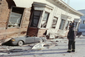
A collapsed house in San Francisco from the 1989 Loma Prieta earthquake. Photo credit: Adam Teitelbaum, AFP, Getty Images.
A collapsed soft-story in San Francisco from the 1989 Loma Prieta earthquake. Photo credit: Adam Teitelbaum, AFP, Getty Images.

Continue Reading