This post is an update to David Finkenbinder’s post on Guard Post Resources from August 13.
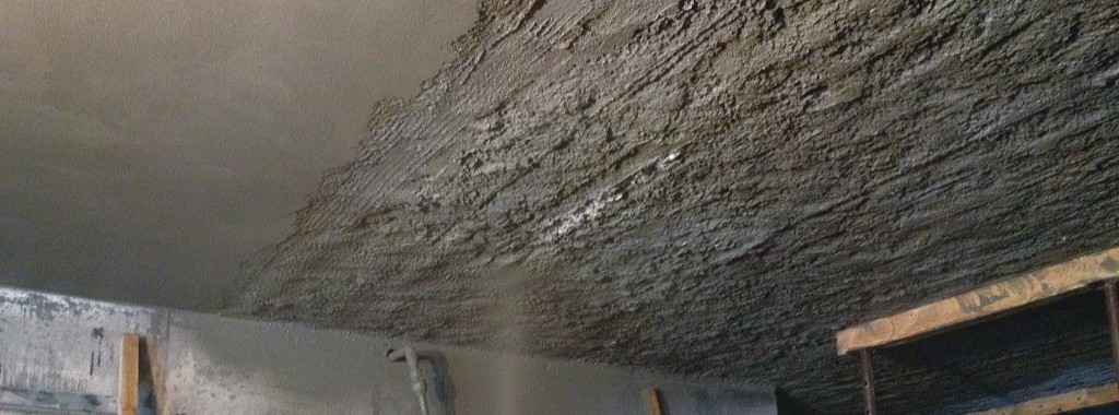
As David explained, the requirements in the IRC and IBC for guards are intended to prevent people from falling off of raised surfaces. The failure of this guard is a common source of injuries caused by failures of deck components.
Section R312.1.1 of the 2012 International Residential Code (IRC) states that “Guards shall be located along open-sided walking surfaces, including stairs, ramps and landings, that are located more than 30 inches measured vertically to the floor or grade below at any point within 36 inches horizontally to the edge of the open side.”
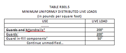
Table 301.5 of the 2012 IRC requires that guards and handrails be designed for “[a] single concentrated load” of 200 pounds “applied in any direction at any point along the top.”
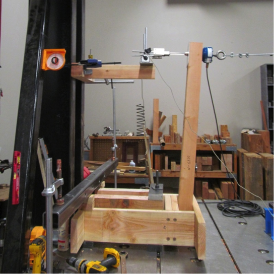
David mentioned the article Tested Guardrail Post Connections for Residential Decks, which described a testing program at Virginia Tech that examined the ability of various assemblies to resist this concentrated load at the top of the guard post. But rather than test in any direction, the researchers decided to test in what they considered the most critical direction: outward away from the deck.
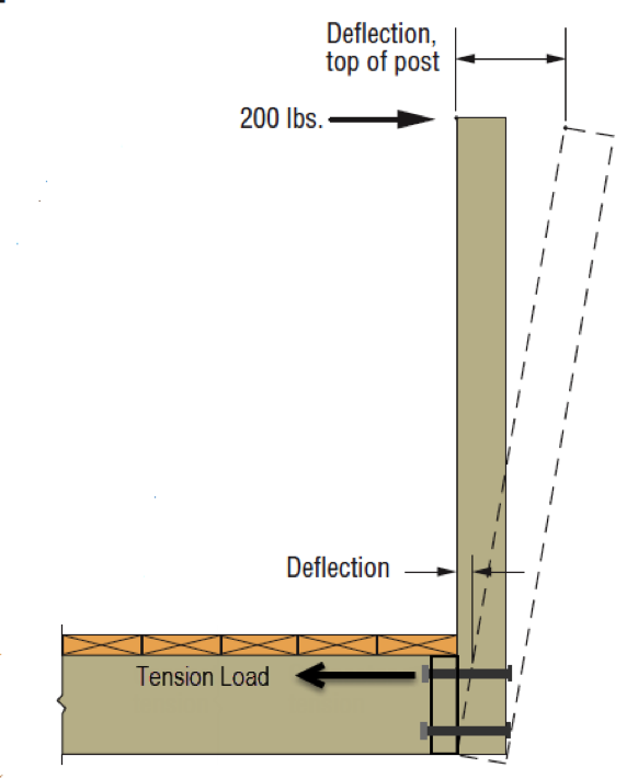
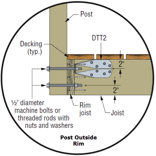
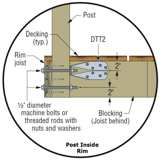
Simpson Strong-Tie subsequently developed a new tension tie, the DTT2Z, to make an economical connection from the top bolt in a deck post back into the framing of the deck to resist the high tension forces that develop in the top bolt when the top of the post is pushed outward. Several details were developed to try to address the various orientations of the post and deck framing.
To allow evaluation of assemblies used to resist this deck guardrail force, ICC-ES developed AC273, Acceptance Criteria for Handrails and Guards. AC273 is available for purchase through the ICC bookstore.
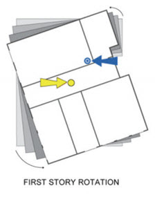
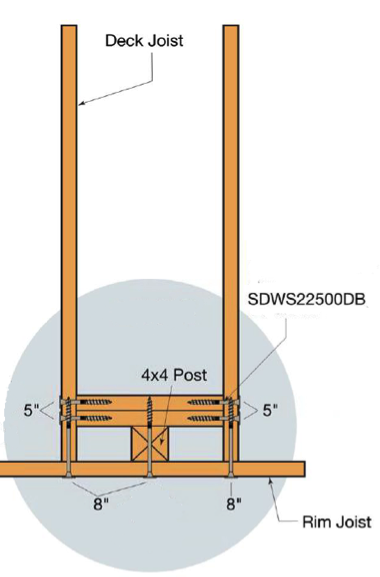
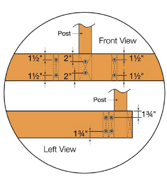
Even with the connectors being readily available, deck builders have asked for guard post connection details that do not involve the use of connection hardware. So Simpson Strong-Tie again tested several framing configurations according to the AC273 criteria, using our Strong-Drive® SDWS TIMBER screws and additional blocking to try to prevent the post from rotating. These details are shown in the engineering letter L-F-SDWSGRD15.
That brings us to the update part.
A committee made up of building officials, manufacturers, deck builders, designers and other interested parties is currently developing a set of code proposals on deck construction for inclusion in the 2018 International Residential Code (IRC). Even though more and more deck information has been incorporated into the last few editions of the IRC, there is still insufficient information in the code to be able to completely build a deck prescriptively. One area of interest is this guard connection. There is a desire to develop prescriptive details for both connection of a 4×4 post to deck framing with blocking and fasteners and for connecting the deck band joist back to the deck framing so that pre-manufactured guard rails can simply be fastened to the deck band with the knowledge that the connection is secure.
The problem is that, with the current requirement, the guard must resist the 200-pound load in ANY direction. All current testing, including AC273, only uses testing in the outward direction away from the floor of the deck. If the post were really required to resist a 200 pound load in the inward direction as well, then two hardware connectors would be required, one on each bolt. However, the belief of the committee is that resistance of 200 pounds in the outward and downward direction is primarily what is needed to ensure the safety of the occupants of the deck.
So they are working on a code proposal to change Table R301.5 of the IRC to require that the guard only resist the 200 pounds in the outward and downward direction and reduce the load to 50 pounds in the inward and upward direction.
The committee recognizes that while this is not necessarily a departure from current practice, it is a departure from current loading requirements in the IRC, IBC, and ASCE 7. So representatives of Simpson Strong-Tie met on September 30 with the NCSEA Code Advisory Committee – General Requirements Subcommittee to get the opinions of this group of active structural engineers. They provided valuable input, including the consideration that at some locations near landings and other changes in elevation, resistance to 200 pounds in the inward direction could be important.
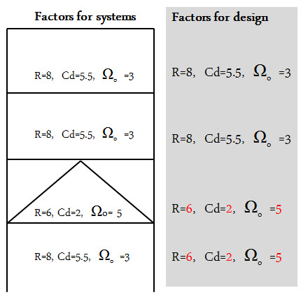
Prior to incorporation of NCSEA’s input, the committee thought the code change might look as shown below.
We are interested in getting additional comments on this code proposal. What do you think? Let us know in the comments below.
d) A single concentrated load applied in any direction at any point along the top, in pounds.
f) Guard in-fill components (all those except the handrail), balusters and panel fillers shall be designed to withstand a horizontally applied normal load of 50 pounds on an area equal to 1 square foot. This load need not be assumed to act concurrently with any other live load requirement.
h) Glazing used in handrail assemblies and guards shall be designed with a safety factor of 4. The safety factor shall be applied to each of the concentrated loads applied to the top of the rail, and to the load on the in-fill components. These loads shall be determined independent of one another, and loads are assumed not to occur with any other live load.
j) A single concentrated load applied at any point along the top, in pounds. The 200-pound load is required to be applied in either the outward or downward direction, and it is permitted to be reduced to 50 pounds in either the inward or upward direction. The guard is not required to resist these loads applied concurrently with each other.