

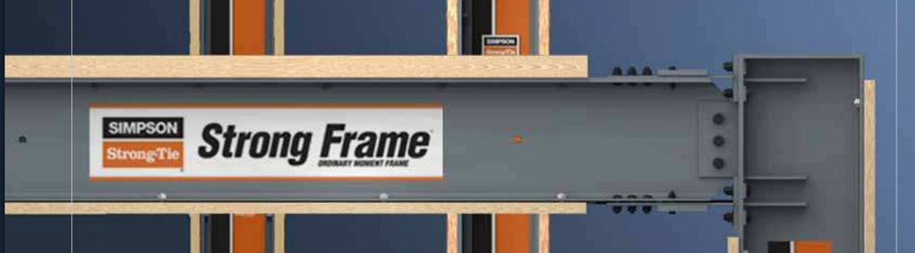
 NOVA, the highest rated science series on television, recently aired a segment on the Colorado State University-led NEES-Soft project that tested Simpson Strong-Tie® Strong Frame® special moment frames as a seismic retrofit solution for soft-story buildings. Simpson Strong-Tie and our special moment frame were prominently featured in the clip. You can watch the entire “Making Stuff Safer” episode on PBS here.
Category: Testing/R&D
Simpson Strong-Tie is constantly testing and innovating.
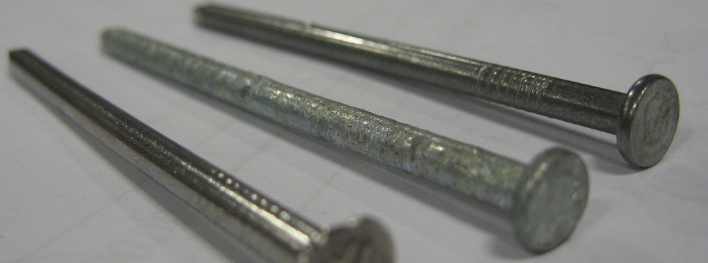
Why Your NDS Nail Calcs Could Be Wrong. . .And What You Can Do About It
This week’s post was written by Bob Leichti, Manager of Engineering for Fastening Systems. Prior to joining Simpson Strong-Tie in 2012, Bob was an Engineering Manager covering structural fasteners, hand tools, regulatory compliance and code reports for a major manufacturer of power tools and equipment. Prior to that, Bob was a Professor in the Department of Wood Science and Engineering at Oregon State University. He received his B.S. and M.S. from the University of Illinois, and his M.S. and Ph.D. from Auburn University.
When test results don’t make sense, we start by eliminating causes of the problem. When our withdrawal test values came up low, we checked the load cell calibration, the specific gravity of the wood, the nail dimensions, even the units – everything was correct. So why were the nail withdrawal values so low? More wood, more nails, more tests – same results. Ultimately, we concluded that the withdrawal resistance of stainless-steel, smooth-shank nails is not well described by the withdrawal function in the 2012 NDS, section 11.2.3, equation 11.2-3.Continue Reading
Not Just A Connector Company
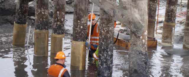
I write a lot about testing on this blog, from my first post about testing to the series I did on how we test different products (hangers, holdowns, fasteners). This week I’d like to highlight some unique testing we’ve been doing to support one of our new product lines. Simpson Strong-Tie® recently introduced our Repair, Protection and Strengthening Systems for Concrete and Masonry. The new product line is the result of our acquisition of Fox Industries, Inc. in 2011.
In the past, I’ve shared some of the more fun tests we’ve run, like the bowling ball test or 40 kip hangers. This week we’ll take a sneak peek at testing of the FX-70® Structural Repair and Protection System. FX-70 uses high-strength fiberglass jackets and high-strength water-insensitive grouting materials to repair and protect wood, steel, and concrete structural members. The system is primarily used on piles in marine environments.
3, 2, 1. . .Countdown to Earthquake!
This week, I’d like to introduce Jeff Ellis as a guest blogger for the Structural Engineering Blog. Jeff is the Manager of Codes, Standards and Special Projects for Simpson Strong-Tie. Jeff will be posting occasionally on topics that are relevant to our work, especially related to cold-formed steel (CFS) construction.
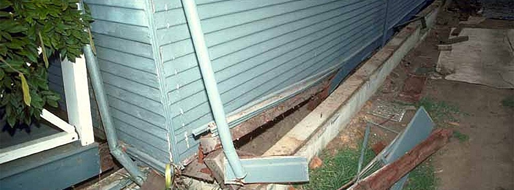
When was the last time you knew an earthquake was coming and witnessed its effects on a building without feeling any shaking yourself? Since the mid- to late ‘90’s, several uni-axial and tri-axial shake tables have been built and used to better understand whole building performance under actual earthquake ground motion in order to improve code requirements and, in some cases, develop performance-based design methods.Continue Reading
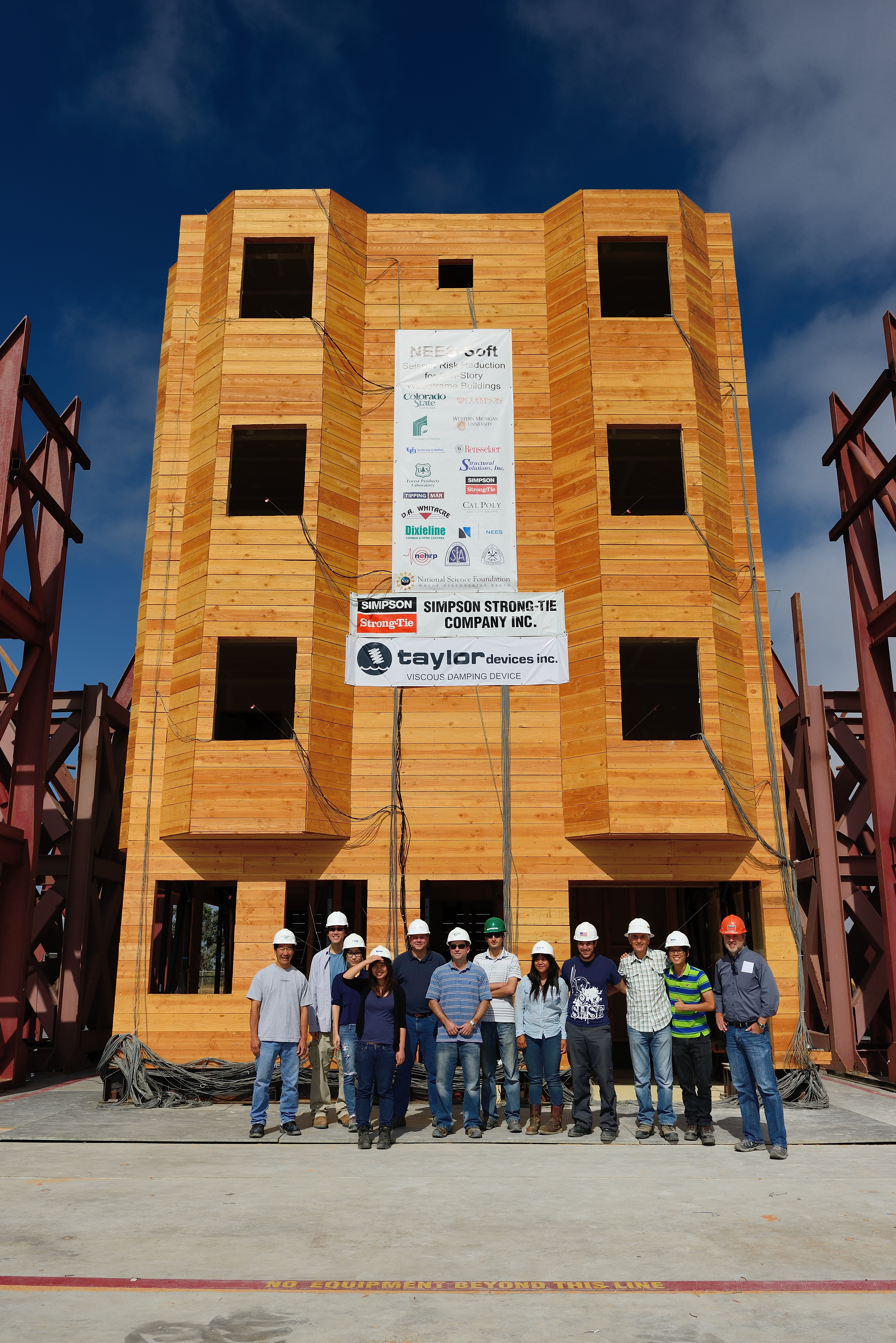
Breaking News: Simpson Strong-Tie® Strong Frame® Special Moment Frame Testing Today
Today the NEES-Soft project has begun testing the steel Simpson Strong-Tie® Strong Frame® Special Moment Frame as a retrofit option for soft-story buildings at the NEES outdoor shake table facility at UC San Diego. The testing is focused on validating the FEMA P-807 design procedure, which attempts to create a least-cost retrofit solution by only retrofitting the garage areas of problem buildings.Continue Reading
Steel Moment Frame Beam Bracing
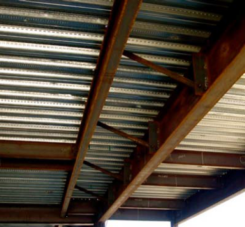
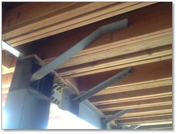
In a previous blog post on soft-story retrofits, I briefly discussed beam bracing requirements for moment frames. This week, I wanted to go into more detail on the subject because it’s important to understand that a typical steel moment frame requires lateral beam bracing to develop its full moment capacity. Figure 1 below shows two common methods of beam bracing. While on the surface determining beam bracing requirements may not appear complicated, there are several items that could prove it to be more challenging than you might think, especially when steel moment frames are used in light frame construction.
Figure 1: Steel Beam Bracing
Before going into beam bracing in steel moment frames, it is important to discuss the behavior of a simply supported beam under gravity load. Short beams (Lb < Lp)[3], might not require bracing to achieve the full plastic moment of the beam section. However, when a beam is long (Lb > Lr) and without bracing, the beam can twist or buckle out-of-plane. Figure 2 illustrates these two behaviors along with the case where the beam length is somewhere in between the two (e.g., Inelastic lateral torsional buckling). In addition, if beam sections are non-compact, flange local buckling (FLB) or web local buckling can occur prior to reaching the beams full plastic moment.
Timber Tower Research Project
In 2009, Simpson Strong-Tie participated in the NEESWood Capstone Test, which was the final experiment in a multi-year study to test and evaluate the seismic performance of various wood-framed buildings. The Capstone Test was a six-story apartment building constructed and tested at the E-Defense test facility, located in Miki, Japan. More information about the Capstone Test is available here.
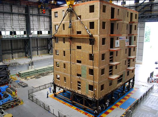
I only mention the NEESWood testing because I thought six-stories was pretty tall for wood-framed construction, since U.S. building codes limit us to four or five stories in wood. I recently came across a research project by Skidmore, Owings & Merrill LLP (SOM) for something just a tad taller than that. Looking to minimize the carbon footprint by using timber as the main structural material, SOM published a report for the design a 42-story, 405-ft. tall building. The solution utilizes mass timber for the main structural elements with reinforced concrete at highly stressed areas. The project used the Dewitt-Chestnut Apartments, a 42-story reinforced concrete structure built in 1965, as the benchmark building.
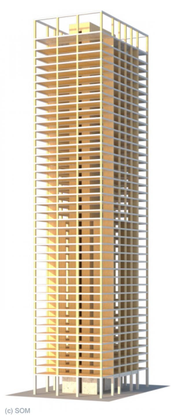
Abstract for the Timber Tower Research Project along with links to the full report and sketches are on SOM’s website.
So, what do you think of a 42-story wood-framed building? Let us know by posting a Comment.
– Paul
What are your thoughts? Visit the blog and leave a comment!
Aren’t We Done Testing Yet?
If you’ve been following the Structural Engineering Blog for any length of time, you’ve probably noticed that we like to run a lot of tests around here. Building test setups and breaking them is one of the things we enjoy the most in R&D at Simpson Strong-Tie, but often load rating a product is not as simple as just running a test. At times the process requires significant time and effort, so much so that we start asking ourselves, Aren’t we done testing yet?
We’ve posted on how we test connectors, holdowns, and screws. Most products have an ASTM standard or Acceptance Criteria that sort of tells you what to test. Yet figuring out how to test a product can be a challenge – in other words, how do we make sure our test simulates installed conditions? Or maybe a product can be used in so many different ways that it is unreasonable to test every possible installation, so what to do?
We have been challenged with these situations over the years, but probably never as much as with our connectors for curtain-wall construction that we introduced about two years ago. In particular, testing our bypass framing connectors to resist in-plane loads (designated as F1 loads) presented testing challenges.
Aren't We Done Testing Yet?
If you’ve been following the Structural Engineering Blog for any length of time, you’ve probably noticed that we like to run a lot of tests around here. Building test setups and breaking them is one of the things we enjoy the most in R&D at Simpson Strong-Tie, but often load rating a product is not as simple as just running a test. At times the process requires significant time and effort, so much so that we start asking ourselves, Aren’t we done testing yet?
We’ve posted on how we test connectors, holdowns, and screws. Most products have an ASTM standard or Acceptance Criteria that sort of tells you what to test. Yet figuring out how to test a product can be a challenge – in other words, how do we make sure our test simulates installed conditions? Or maybe a product can be used in so many different ways that it is unreasonable to test every possible installation, so what to do?
We have been challenged with these situations over the years, but probably never as much as with our connectors for curtain-wall construction that we introduced about two years ago. In particular, testing our bypass framing connectors to resist in-plane loads (designated as F1 loads) presented testing challenges.
Continue Reading
Are the Load Combinations Balanced?
In April’s post about the Omega Factor, one commenter asked of the 1.2 increase allowed by ASCE 12.4.3.3, “Why do they allow a stress increase for allowable combinations? Seems unconservative for steel now that they have essentially balanced the ASD capacity with LRFD.”
To be honest, I have never spent much time analyzing which design methodology was more or less conservative. If I was designing with wood I would use ASD, and if it was with concrete I would use LRFD. Steel was strictly ASD early on in my design career, but LRFD usage grew. The question about balance made me curious. Are the load combinations balanced?
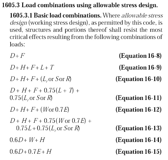
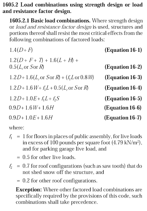
Of course, just comparing the load combinations would be meaningless. We know the LRFD combinations result in higher design forces. But those higher forces are compared to higher design strengths. So we need to normalize things.