


On the About Paul McEntee page of this blog, I told the story about hosting Take Our Daughters and Sons to Work Day, which was four years ago. My son Ryan then described my job as, “Goes and gets coffee and sits at his desk.” I don’t know what my daughter Kira would have said about my job, as she was too young to attend back then, but ever since I took her brothers she has been asking, “Daddy, when do the kids get to go to your work again?” So, of course, we just had to have this event again this year on April 30.Continue Reading
Category: Testing/R&D
Simpson Strong-Tie is constantly testing and innovating.

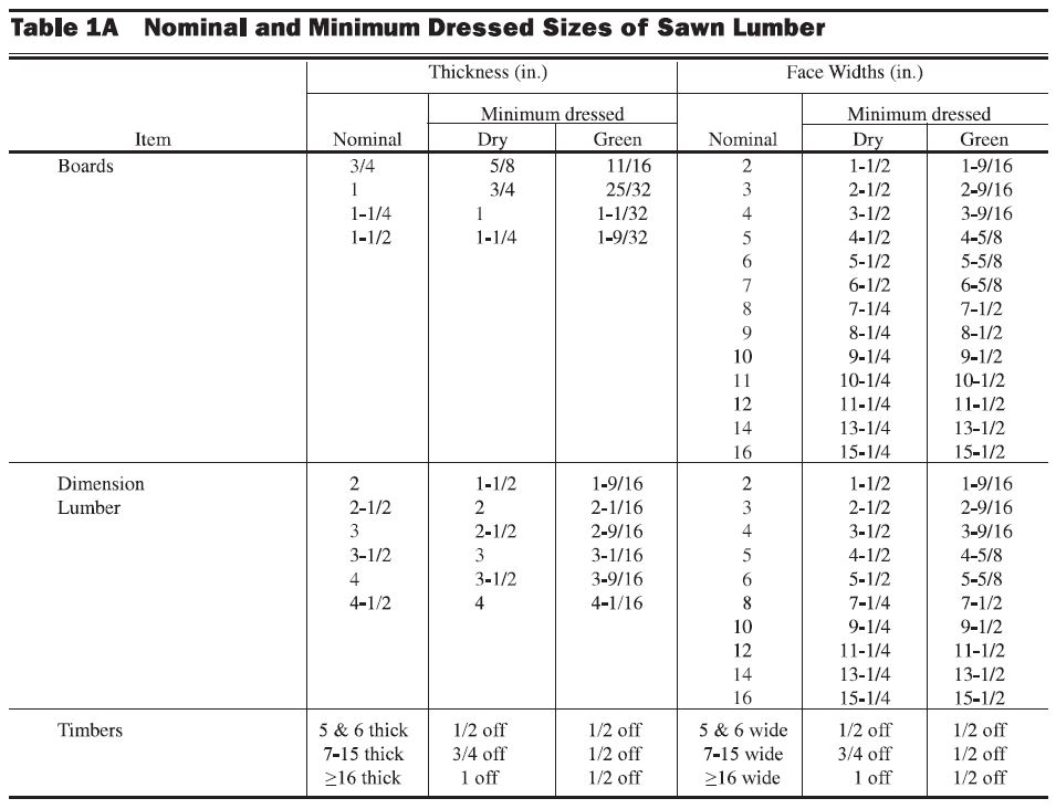
Why Won’t The Wood Fit? Understanding Lumber Size
Lumber size is often given in “nominal” measurements. This can often lead to confusion when someone is shopping for wood and wood connectors. Paul McEntee, Simpson Strong-Tie Manager of Engineering R&D, addressed lumber sizes and how our company takes them into consideration during product development and testing.
Why Won't The Wood Fit?
Your wood fastening products seem to be built for yesteryear wood sizes. 2x’s are no longer larger than 1½”. Why can’t you manufacture these products with a little closer tolerance?
I received this question from a customer a few days ago via Ask Simpson, a web page where you can submit technical questions to our Engineering Department and we respond by e-mail. We have received similar variations of this question countless times over the years, so I thought it could use some discussion.
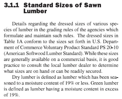
The National Design Specification for Wood Construction (NDS) Supplement Table 1A “Nominal and Minimum Dressed Sizes of Sawn Lumber” gives the minimum dry and green dimensions for sawn lumber. This specifies a nominal 2x, for example, as being 1½” dry and 1 9/16” green. NDS Supplement Section 3.1.1 defines dry lumber being seasoned to a moisture content of 19% or less, whereas green lumber is higher than 19%.
So what size do you make the connector?
Continue Reading

2012 Autodesk University
Autodesk University is an annual conference focused on keeping the design community up to date on the latest innovations, trends and technologies in design, drafting and visualization. Last year, Autodesk University was held in Las Vegas the week after Thanksgiving. Sadly, events always seem to conspire to prevent me from going to Vegas, but Simpson Strong-Tie was well represented by Frank Ding, our Engineering Analysis & Technical Computing Manager.
It was an exciting time attending my first Autodesk University in 2012. I have been to so many technical conferences during my professional career, but this one was quite different in scale, and the sheer size of it just blew me away. There were more than 8,000 attendees from 102 countries, more than 750 classes offered, and 163 exhibitors. I was impressed by the organization of such a large event, along with the online and mobile apps provided to help attendees manage their conference schedules.Continue Reading
Open Front Structure Wind Pressure Design
We received a request from Martin H., one of our blog readers, to discuss the method for determining roof wind pressures on an open front agricultural building. The inquiry was regarding clarification on analyzing the roof pressure when a combined external and interior pressure exists and whether these are additive.
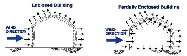
As can be seen in the above illustrations, the net design pressure on the roof is the sum of the uplift on the exterior surface and the uplift on the interior surface from any internal pressure. ASCE 7 provides a method for determining this pressure. Specifically, ASCE 7-10 will be used for the remainder of this post. Assuming the three remaining sides of the open front structure are walls without openings, the building will be classified as partially enclosed by the definitions of Section 26.2.
ASCE 7-10 provides for two methods for determining the Main Wind Force Resisting System (MWFRS) wind loads for partially enclosed buildings, the Directional Procedure in Chapter 27, and the Envelope Procedure in Chapter 28.
When using the Directional Procedure, the net wind load is calculated using the following equation:
P = qGCp – qi(GCpi)
When using the Envelope Procedure, the net wind load is calculated using the following equation:
P = qh[(GCpf) – (GCpi)]
In each of these equations, the first portion determines the pressure on the exterior surface, and the second portion determines the pressure on the interior surface. So the variable for calculating the internal pressure is the internal pressure coefficient GCpi.
The internal pressure coefficient is provided in Table 26.11-1 based on three different categories of building enclosure.
Enclosure Classification | (GCpi) |
| Open Buildings | 0.00 |
| Partially Enclosed Buildings | +0.55 -0.55 |
| Enclosed Buildings | +0.18 -0.18 |
Table 26.11-1
In the case of an open front structure, it is assumed that the partially enclosed internal pressure coefficient must be used. This coefficient is 3x greater than when the building envelope is classified as enclosed. Use of this higher coefficient in the design will account for the interior pressure on the underside of the roof combined with the exterior pressure.
MWFRS versus C&C
Another somewhat related question: to what level loads should the roof anchorage forces be calculated, MWFRS or C&C (Component and Cladding)? I have often been asked this question, and wrote a Technical Note published by CFSEI (Cold-Formed Steel Engineers Institute) in July 2009.
What are your thoughts?
– Sam
What are your thoughts? Visit the blog and leave a comment!
Lab Statistics – How Much Wood?
Like many people with desk jobs, I just have to get up and walk around every once in a while. Most of my walks are through our connector test lab at our home office in Pleasanton, California. The lab technicians install a lot of products for testing, so in addition to stretching my legs, I like to quiz them for ideas on things we can do to make installation faster and easier for our products.
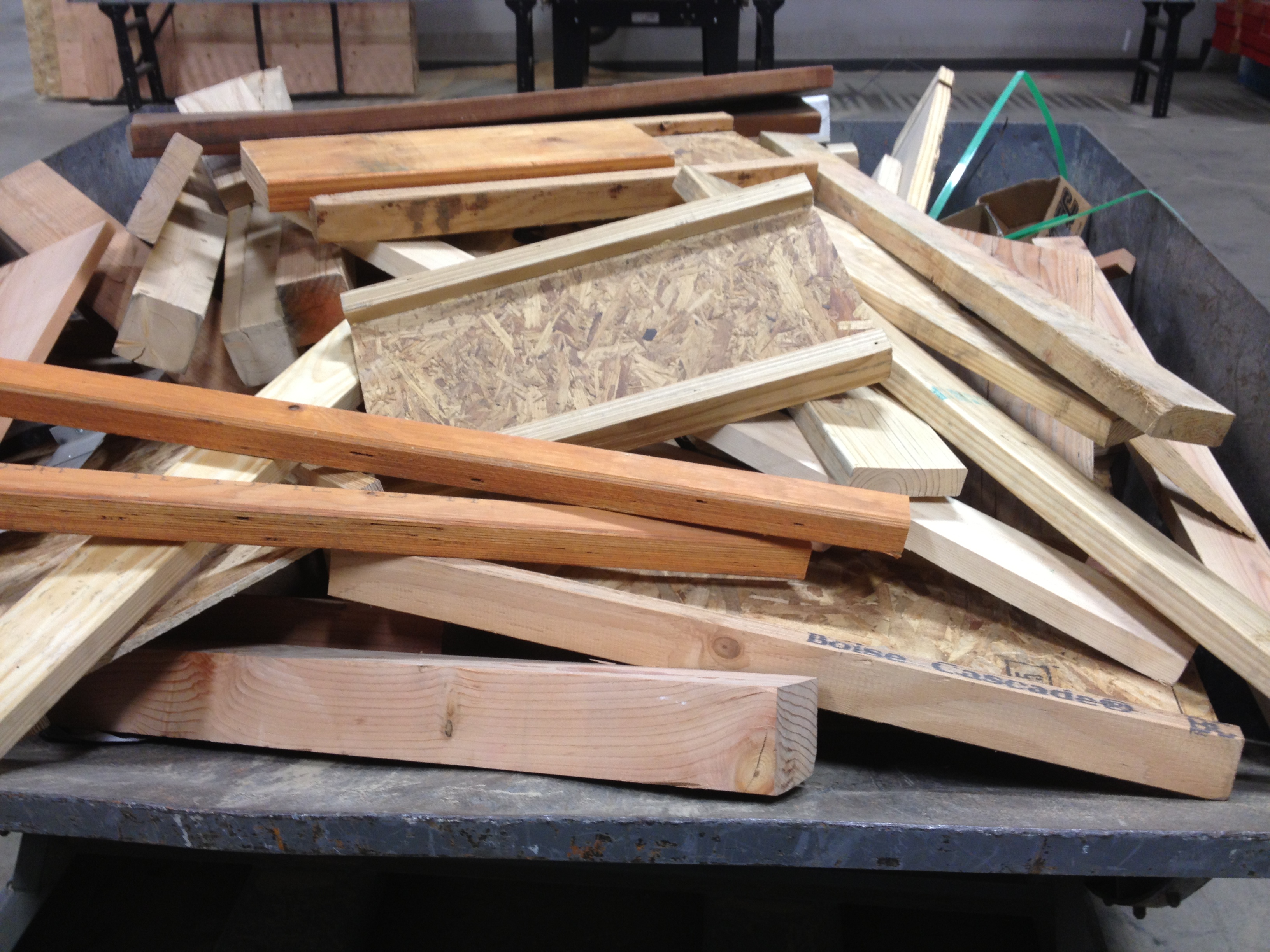
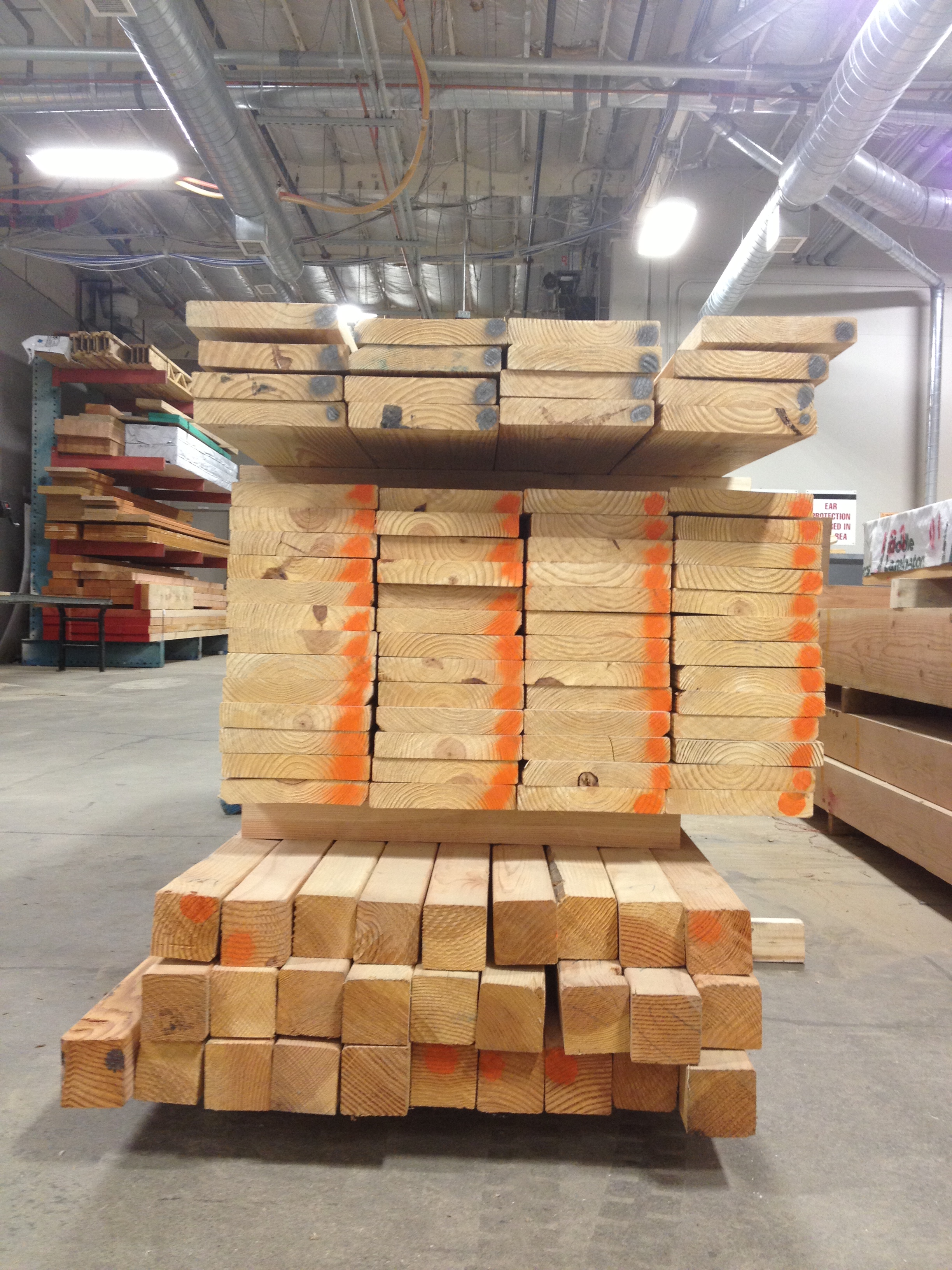
During one of my walks this week, a lab technician was finishing up a rather extensive test setup that consumed a large quantity of lumber, screws, and truss plates. I asked him how it was going and he commented, “Testing isn’t exactly environmentally friendly, is it?”
Before I could even respond, he added, “I guess that’s just part of the price of building safer buildings.” I like the way he thinks.
So, What’s Behind A Screw’s Allowable Load?
This is Part 2 of a four-part series I’ll be doing on how connectors, fasteners, anchors and cold-formed steel systems are load rated. Read Part 1 and Part 1A.
These loads just can’t be right! Occasionally, I get this statement from engineers. This happens when they have been specifying commodity fasteners based on NDS load values and they get their first look at our higher screw values. Then the call comes in. They want to talk to someone to confirm what they are seeing is correct. I assure them the loads are right and give them this brief overview of how we got here:
Our first structural screw, the Simpson Strong-Tie(R) Strong-Drive(R) SDS, was originally load rated by plugging the bending yield strength and diameter into the NDS yield limit equations and using the load value from the governing failure mode. As later editions of the NDS modified the calculations and we did more testing, we found that the tested ultimate load of the SDS screw could be as much as ten times greater than the allowable load generated from the NDS equations.
So, What's Behind A Screw's Allowable Load?
This is Part 2 of a four-part series I’ll be doing on how connectors, fasteners, anchors and cold-formed steel systems are load rated. Read Part 1 and Part 1A.
These loads just can’t be right! Occasionally, I get this statement from engineers. This happens when they have been specifying commodity fasteners based on NDS load values and they get their first look at our higher screw values. Then the call comes in. They want to talk to someone to confirm what they are seeing is correct. I assure them the loads are right and give them this brief overview of how we got here:
Our first structural screw, the Simpson Strong-Tie(R) Strong-Drive(R) SDS, was originally load rated by plugging the bending yield strength and diameter into the NDS yield limit equations and using the load value from the governing failure mode. As later editions of the NDS modified the calculations and we did more testing, we found that the tested ultimate load of the SDS screw could be as much as ten times greater than the allowable load generated from the NDS equations.
Continue Reading
Load Testing, Last Day To Enter Our Contest, And Happy Holidays!
With all of the frenzy that happens before (and during) the holidays, I won’t be doing full blog posts this or next week. But, I did want to remind you that this Thursday (12/20) is the last day to enter our “Creative Uses of Our Product” contest. We’ll post our five winners to the blog next week.
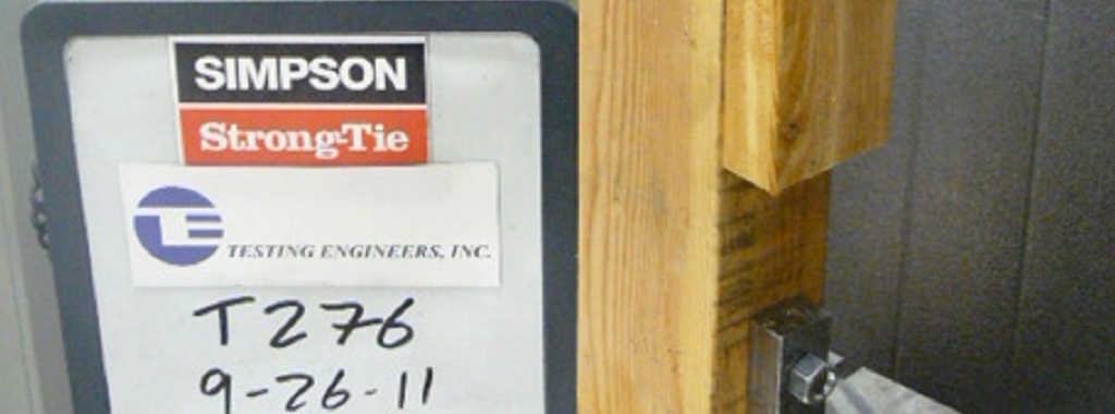
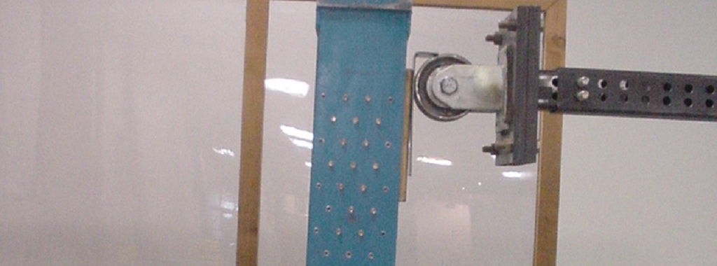
This week will be a short snapshot into what we were doing yesterday. We are always testing products and usually the only people who stop by to watch the tests besides the lab technicians are an R&D engineer and occasionally the product manager. As valuable as testing is, the simple day-to-day stuff just doesn’t generate much excitement – crushing bowling balls is fun and gets a crowd, but we save that for orientation classes.
So, What’s Behind A Structural Connector’s Allowable Load? (Holdown Edition)
This is Part 1A of a four-part series I’ll be doing on how connectors, fasteners, anchors and cold-formed steel systems are load rated.
I envisioned doing a four-part series on how connectors, fasteners, anchors, and cold-formed steel are load rated. After writing the first installment on connectors, I realized that connectors are a bit more complicated, since the testing and evaluation for joist hangers (or similar devices) is different than testing for holdown devices. And I wanted to discuss holdowns. So without belaboring the apology for my numbering system, this will be part 1A of the series – still discussing wood connectors, but focusing on holdowns and some of the unique requirements in their load rating.Continue Reading