

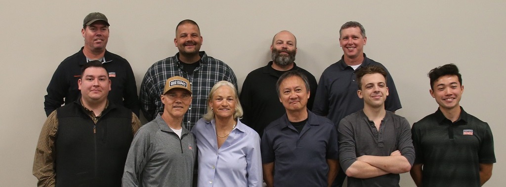
David Huerta, Senior Lab Manager at the Simpson Strong-Tie home office in Pleasanton, California, was present during the renaming of the Karen Colonias Research Laboratory. The lab was renamed in honor of our former CEO, Karen Colonias, who was instrumental in driving our company forward during her 38 years with the company, including 11 as our CEO. David shares his perspective on the lab’s functions and operations, as well as its importance to our company’s legacy.
Category: Uncategorized
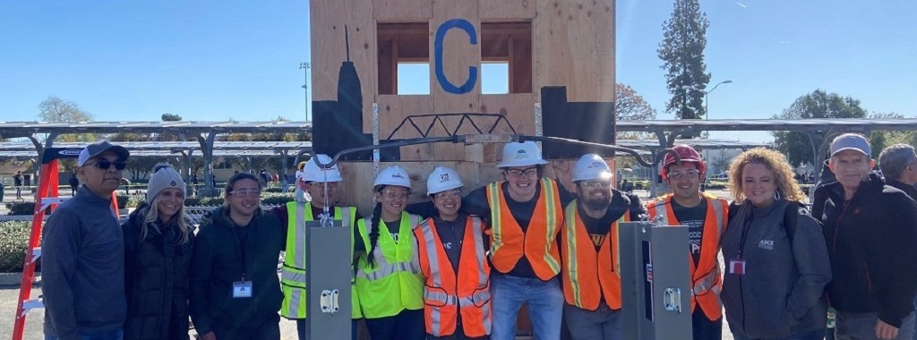
Empowering Future Engineers: Cal Poly Students’ Journey in the Timber-Strong Design Build Competition
The Timber-Strong Design Build℠ (TSDB℠) Competition is an annual event sponsored by the the American Society of Civil Engineers (ASCE) in partnership with the American Wood Council (AWC), APA (the Engineered Wood Association), and Simpson Strong-Tie in which student teams design and build an artistically creative two-story wood light-framed buildings that are sustainable, aesthetically pleasing, and structurally durable. The competition enables students to gain experience in common structural engineering design as well as the business management and building practices used in construction environments. The authors of this article are graduating civil engineering students in the Civil Engineering program at California Polytechnic State University in San Luis Obispo, CA.
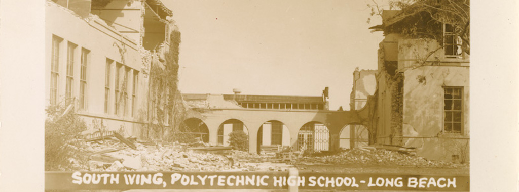
90 Years Later — How the Long Beach Earthquake Changed California’s Approach to School Construction
On March 10, 1933, around dinnertime, a magnitude 6.4 (Mw) earthquake struck the Long Beach area of California just before 6 p.m., causing widespread damage and resulting in 120 fatalities. This earthquake became a turning point in the way that earthquakes and their impacts were understood and addressed in the western US.
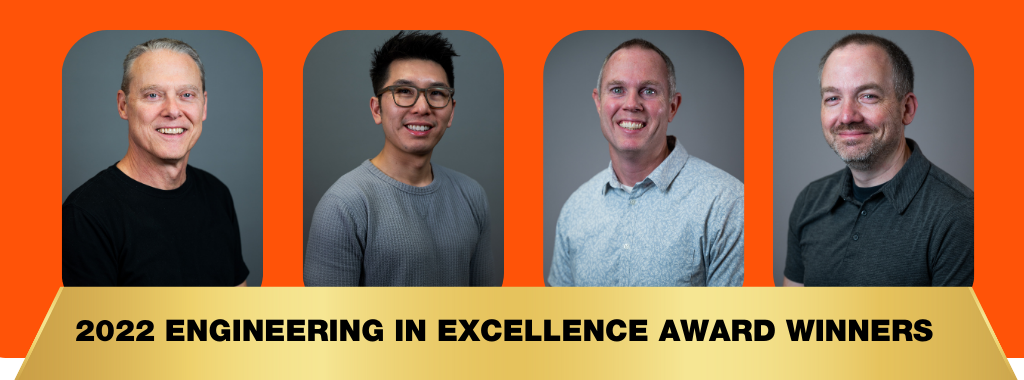
Bringing Excellence to Engineering: Meet Our 2022 Excellence in Engineering Award Winners
This year, the Simpson Strong-Tie Engineering department held their 2023 Engineering Summit and awarded four engineers the 2022 Excellence in Engineering Award. This award recognizes the incredible contributions from our Engineering department, who continually exceed expectations in their mission to create the best solutions we can for our customers and our company.

What Is the Buy America Act?
Simpson Strong-Tie Senior Field Engineer Nehal Patel breaks down the Buy America Act- passed in 1933, which requires the federal government to buy American–made iron, steel, and manufactured goods wherever possible. He dives into the legislative action and how it relates to Simpson Strong-Tie.

How Getting an MBA Can Help You Elevate Your Engineering Career
In case you missed it, Damon Ho, the segment market manager for Prefabricated Lateral Systems at Simpson Strong-Tie, joined The #StructuralEngineering Channel podcast as a special guest. During the podcast, Damon discussed how getting an MBA can benefit an engineering career and the types of careers that engineers with an MBA can pursue. He received his B.S. in architectural engineering and MBA from Cal Poly, San Luis Obispo. After practicing structural engineering, he later obtained his master’s in civil engineering from the University of Canterbury, New Zealand.
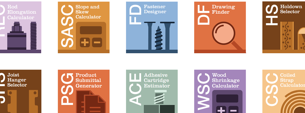
Top Five Simpson Strong-Tie® Tools for Engineers This Year
The beginning of a new year is a great time to work towards resolutions, such as “Work Smarter, Not Harder.” So what better time to check out tools and resources that can help you design structures and specify products more efficiently? Working more efficiently means gaining more time, something we can all use a little more of.

Top Structural and Wood-Related Changes in the 2021 IRC, Part 2
In the last post, we described the primary structural and wood-related changes in the 2021 International Residential Code, Chapters 3 and 4. This post will continue with the primary changes to Chapters 5 through 8 of the IRC.
Top Structural and Wood-Related Changes in the 2021 IRC, Part 1
The ICC code change cycle for the 2024 International Codes is near completion, with only the certification by the Validation Committee and confirmation by the ICC Board of Group B results outstanding. However, many jurisdictions may just now be adopting the 2021 International Codes. This is the first of three posts that will discuss the primary structural and wood-related changes in the 2021 International Residential Code and International Building Code. This post covers changes to IRC chapters 3 and 4, organized by subject. Continue Reading
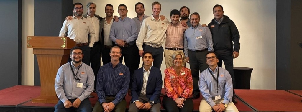
Simpson Strong-Tie in Latin America: Our 2022 Chile Seminar
Our Director of International Sales in Latin America, Cyndi Chandler, organized our annual sales seminar in Chile. This was a great opportunity to connect with our engineers and specifiers in Latin America and educate them about the various products and resources we offer. Learn more about this dynamic two-day seminar and the products we demonstrated in Chile.