Installation Errors – They Happen

A few years ago, we did a post on creative uses of our products. Most of the uses shown were artistic, or functional do-it-yourself projects, with one odd car spoiler modification. This week, I was reviewing some slides in a presentation that I give a few times a year regarding product installation errors. I call them misinstallations, but I’m not sure that’s a word. I thought I’d share a few of the more instructional ones. Most of the photos were curated by our northwestern region training manager, Olga Psomostithis – thanks Olga!

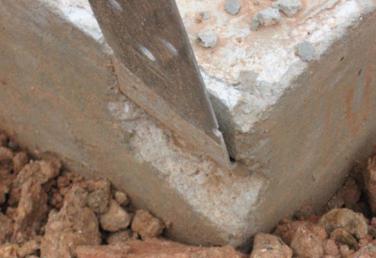
Double Shear Hangers

install1

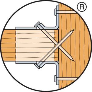
Double shear hangers require joist fasteners that are long enough to penetrate through the hanger, through the joist and into the header. The joist nails help transfer load from the joist into the header, resulting in higher allowable loads.

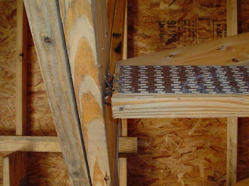
install2.1

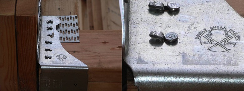
The installation shown has had the double shear tabs bent back, and nails installed straight into the joist. Since the joist nails do not penetrate the header, this would result in a reduced capacity.

Holdowns

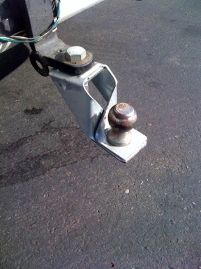
I’m including the trailer hitch installation because it makes me laugh no matter how many times I see it.

install4

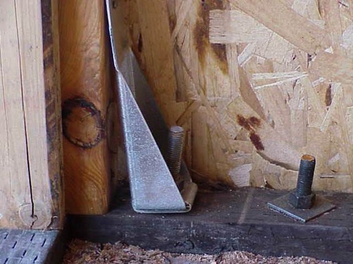
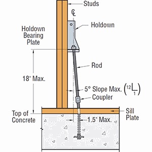
A very common question we get about holdowns is related to posts being offset too far from the anchor bolt (or is the anchor too far from the post?). In the installation shown below, the holdown is not flush with the post as the anchor bolt is offset about 1 inch. For small offsets up to about 1½”, a common solution is to raise the holdown off the sill plate and extend the anchor bolt with a coupler and bend it so there is a small (1:12) slope to it.

install5

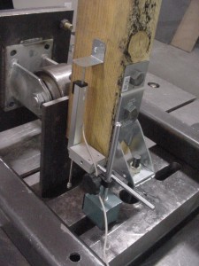
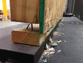
The holdown test standard, ICC-ES AC155, which is discussed in this post, requires that holdowns are tested raised off the test bed, which you can see in the photo below. Holdowns may be raised up to 18” above the top of concrete without a reduction in load provided that the additional elongation of the anchor rod is accounted for.

install6

install7

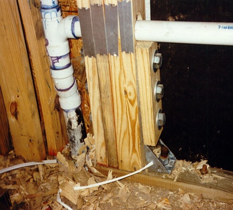
I like this photo because the installer put on the nail stops to protect the pipes. It is good to remember that plumbing happens when laying out a structural system.

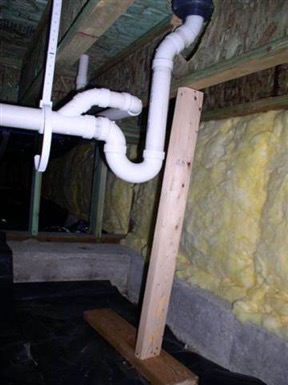
Oh boy, does it happen.

install9STHD Holdowns

install12

install16

The photo above is not a misinstallation, but something that can happen. Embedded strap-style holdowns are cost-effective solutions for shearwall overturning or wind uplift. It is permitted to bend the straps to horizontal and back to vertical one cycle. If spalls form, they should be evaluated for reduced loads. Any portion of the strap left exposed should be protected against corrosion.

Hanger Gaps

install13

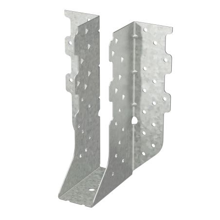
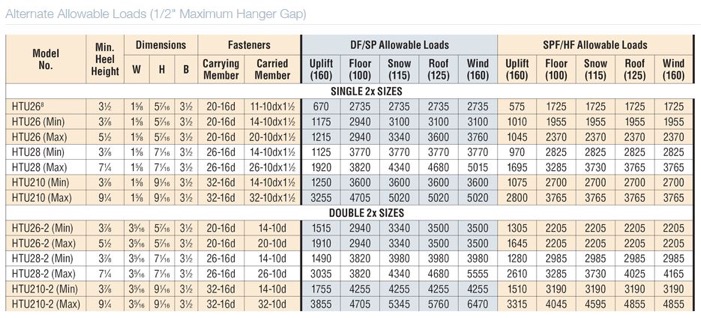
Gaps can occur between trusses and supporting girders for a variety of reasons. For standard hanger tests, a 1/8″ gap is required between the joist and header per ASTM D7147. A resource for evaluating conditions with larger gaps is our technical bulletin Allowable Loads for Joist Hangers with Gaps. The technical bulletin has load data for a variety of hangers with gaps up to 3/8″, as well as recommended repairs for larger gaps. Our HTU product series comprises truss hangers specifically engineered to allow gaps up to ½”.

install14

install15

After going through a design project and carefully selecting the members and details of construction, it can be frustrating as an engineer to get that phone call from the general contractor or building inspector informing you that something is not right with the construction. Understanding some of the resources available to address installation errors can help solve these problems more quickly, and get you back to designing the next project.

Impact Community Resilience as a USRC Member and Certified Rater

The U.S. Resiliency Council (USRC) recently launched its Building Rating System for earthquake hazards. The Rating System assigns a score of from one to five stars for three building performance measures: Safety, Damage (repair cost) and Recovery (time to regain basic function).Continue Reading

Simpson Strong-Tie Now Offering a Structural Engineering/Architecture/Construction Management Student Scholarship Program

We know it’s tough going to school and majoring in structural engineering or architecture. You probably weren’t aware of this, but I went to Brooklyn Technical High School and we were required to take mechanical drafting, electrical engineering and wood/metal shop before we selected majors at the end of our sophomore year. I actively avoided majoring in architecture and engineering because, while I was a whiz at the lathe in metal shop, I was much less talented in some of the other engineering subjects.

draft1
Mechnical drafting class in Brooklyn Technical High School. (Photo courtesy of Brooklyn Technical High School)

I sometimes wish I had been better at them, because getting a degree in structural engineering and architecture isn’t just cool (where else can you get college credit or money to break stuff?), it can help you improve the lives of others and even make them safer. Simpson Strong-Tie Company, Inc. established the structural engineering/architecture scholarship program to assist architecture and structural engineering students by supporting their education and encourage them to design and build safer structures in their local communities.

And it seems as though there are more and more students committed to those goals, too. Last year, Simpson Strong-Tie awarded 49 scholarships of $2,000. The year before, Simpson Strong-Tie awarded 38 scholarships of $1,000. This year, Simpson Strong-Tie is offering up to 67 scholarship awards of $2,000 for the 2016/2017 academic school year. Applicants must be enrolled as juniors or seniors in full-time undergraduate study (60 semester hours or equivalent) majoring in architecture, structural engineering or construction management at the following colleges or universities for the entire upcoming academic year:

  • Arizona State University
  • Boise State University
  • Brigham Young University
  • California State Polytechnic University, Pomona
  • California State Polytechnic University, San Luis Obispo
  • California State University, Fresno
  • California State University, Fullerton
  • California State University, Long Beach
  • California State University, Sacramento
  • Clemson University
  • Florida International University
  • Georgia Institute of Technology
  • Iowa State University
  • Louisiana State University
  • Milwaukee School of Engineering
  • NYU Polytechnic School of Engineering
  • North Carolina State University
  • Ohio State University, Columbus
  • Oklahoma State University
  • Oregon Institute of Technology
  • Oregon State University
  • Penn State University Park
  • Portland State University
  • Purdue University, West Lafayette
  • Southern California Institute of Architecture
  • Texas Tech University
  • University of Arizona
  • University of California, Berkeley
  • University of California, Davis
  • University of California, Irvine
  • University of California, Los Angeles
  • University of California, San Diego
  • University of Cincinnati
  • University of Florida
  • University of Idaho
  • University of Illinois at Urbana-Champaign
  • University of Miami
  • University of Michigan
  • University of Nevada, Las Vegas
  • University of North Texas
  • University of Southern California
  • University of Texas, Arlington
  • University of Texas, Austin
  • University of Washington
  • University of Wyoming
  • Virginia Polytechnic Institute and State University
  • Washington State University


The scholarship application will be available on the Simpson Strong-Tie website as of March 15, so if you know any students enrolled in a structural engineering, architecture or construction management major at the schools listed above, you should advise them about this wonderful opportunity. If you have any questions or comments, please let us know in the comments below.

Mass Timber Construction – Building for the Future

The future is here and that future is mass timber construction.

It is common knowledge that wood is a renewable and environmentally friendly building material. There are two types of wood-framing methods in North America. The most common method for residential construction is light-frame construction using either balloon-framing or platform-framing methods. Standardized dimensional lumber has become the dominant building material in light-frame construction because of its economy. The other method is heavy-timber construction, which often uses large solid-wood sections for nonresidential construction, such as for storage, mercantile and industrial buildings.

In Europe, there is a trend to create larger “laminated” wood sections using the more traditional standardized dimensional lumber of the 1990s. This trend culminated in what is now classified as cross-laminated timber, or CLT. CLT can be used to create floor panels and roof panels. In North America, this is classified either as cross-laminated timber (CLT) or generically as mass timber.

CLT is essentially multiple layers of wood panels. Each layer of wooden panels is laid crosswise on the one before at approximately a 90° angle and glued using a polyurethane adhesive to increase the stability of the entire panel. Typical thickness of the individual boards can vary from 3/8″ to 2″ thick. Typical board width can vary from 2-3/8” to 9-1/2” wide. CLT panels are fabricated and marketed from 3-ply CLT up to 7-ply CLT. CLT mass timber side viewmanufacturers normally publish characteristic properties for their panels – such as bending strength, shear strength, modulus of elasticity and panel stiffness – to assist Designers in specifying these products.

A Cross Laminated Timber Handbook has been published by FPInnovations in Canada as an introduction to CLT. This handbook can be downloaded for free here. The American Wood Council has a self-study guide on CLT that can be downloaded here.

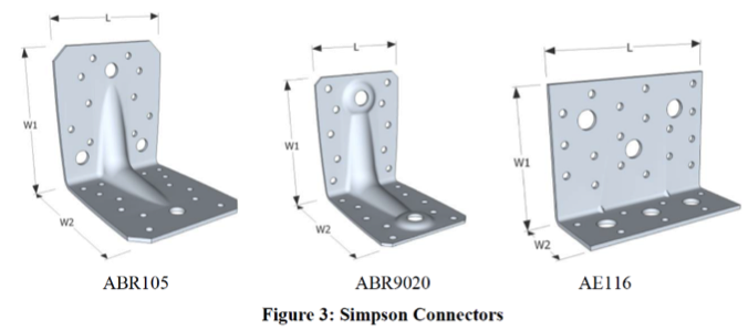
As in all wood buildings, connection designs are critical to the success of this new type of building material. Simpson Strong-Tie offices in Europe have been instrumental in developing and supplying connectors and fasteners in the CLT market. Simpson Strong-Tie has developed many connectors specifically for the CLT market in Europe (Figure 3).

mass timber simpson clt connectors

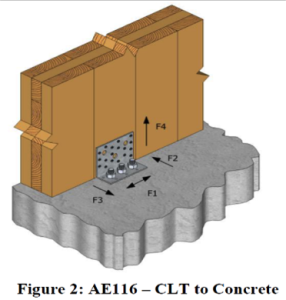
Those connectors are used to join the CLT floor panels to CLT wall panels and CLT wall panels to the concrete foundation (Figures 1 and 2).

mass timber ABR105  CLT panel connection

mass timber AE116 CLT to concreteSpecialized ring-shank nails and long metal screws have been developed as well. In mid-2014, Simpson Strong-Tie North America (Pleasanton, California Testing Facility) embarked on an initial test program to assess those connectors and fasteners developed for the CLT market by Simpson Strong-Tie Europe, using North American CLT panels to verify and quantify the performance characteristics according to North American testing protocols (American Society for Testing and Materials and Canadian Construction Materials Centre).

The initial test program used CLT panels fabricated in Western Canada using Canadian Spruce-Pine-Fir (S-P-F) lumber. The connectors and ring-shank nails were imported from the Simpson Strong-Tie European manufacturing facilities. Testing of the connectors also included the Simpson Strong-Tie Strong-Drive® SD screws, which as expected, provided higher load capacity than the ring-shank nails. A summary of the test program and the load rating developed for both the Canadian and the U.S. market can be downloaded here.

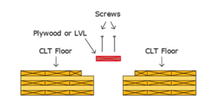
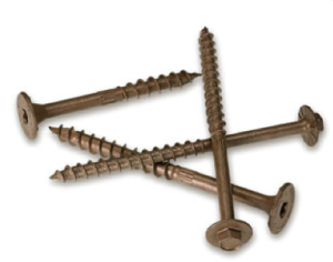
Other types of long countersunk screws such as the Strong-Drive® SDWS Timber screw (countersunk) or Strong-Drive SDWH Timber-Hex (hex head) screw (shown) are used either to splice the floor panels together or to drag the diaphragm loads back to the column or post as necessary.

mass timber cat floorfasteners for mass timber

As CLT continues to gain acceptance in North America, other connection details will also become more popular. Simpson Strong-Tie intends to continue developing and improving connection details to support this type of construction.

Building code acceptance is another important requirement and development that is in progress in both Canada and the U.S. In Canada, the 2014 edition of CSA O86 “Engineering Design in Wood” has reserved a section for CLT.

The 2015 edition of the International Building Code (IBC) recognized CLT when it is manufactured to the product standard. CLT walls and floors will be permitted in all types of combustible construction. The 2015 National Design Specification (NDS) for Wood Construction was recently published and approved as an ANSI American National Standard. The 2015 National Design Specification is also referenced in the 2015 IBC.

The future is here. Environmentally friendly mass timber (including CLT) is poised to grow in use, especially with the recognition of CLT in the building codes. North American manufacturing of CLT has been established and can only grow to support the expanding use of this new building material.

References:

www.cwc.ca

www.awc.org

https://fpinnovations.ca

*Images with permission from FPInnovations


Shrinkage Compensation Devices

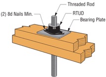
Over the weekend, I had the pleasure of watching my daughter in her cheer competition. I was amazed at all the intricate detail they had to remember and practice. The entire team had to move in sync to create a routine filed with jumps, tumbles, flyers and kicks. This attention to detail reminded me of the new ratcheting take-up device (RTUD) that Simpson Strong-Tie has just developed to accommodate 5/8″ and ¾” diameter rods. The synchronized movement of the internal inserts allows the rod to move smoothly through the device as it ratchets. The new RTUDs are cost effective and allow unlimited movement to mitigate wood shrinkage in a multi-story wood- framed building. When designing such a building, the Designer needs to consider the effect of shrinkage and how to properly mitigate it.

Our SE blog post on Continuous Rod Restraint Systems for Multi-Story Wood Structures explained the importance of load path and  the effects of wood shrinkage. This week’s blog post will focus on the importance of mitigating the shrinkage that typically occurs in multi-story light-frame buildings.

Shrinkage is natural in a wood member. As moisture reaches its equilibrium in a built environment, the volume of a wood member decreases. The decrease in moisture causes a wood-framed building to shrink.

The IBC allows construction of light-framed buildings up to 5 and 6 stories in the United States and Canada respectively. Based on the type of floor framing system, the incremental shrinkage can be up to ¼” or more per floor. In a 5-story building, that can add up to 1-¼” or more and possibly double that when construction settlement is included.

rods1
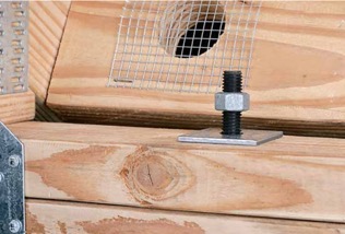
Typical Example of gap forming between nut and plate when wood shrinkage at top level occurs without shrinkage device.

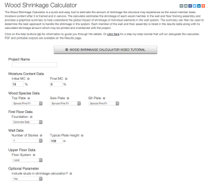
The Simpson Strong-Tie Wood Shrinkage Calculator is a perfect tool to determine the total shrinkage your building can experience.

Wood Shrinkage Calculator

In order to accommodate the shrinkage that occurs in a multi-story wood-framed building, Simpson Strong-Tie offers several shrinkage compensating devices. These devices have been tested per ICC-ES Acceptance Criteria 316 (AC316) and are listed under ICC-ES ESR-2320 (currently being updated for the new RTUD5, RTUD6, and ATUD9-3).

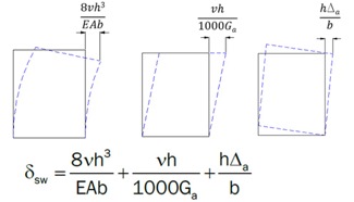
AC316 limits the rod elongation and device displacement to 0.2 inches between restraints in shearwalls. This deflection limit is to be used in calculating the total lateral drift of a light-framed wood shearwall.

rod3
3 Part Shearwall Drift Equation

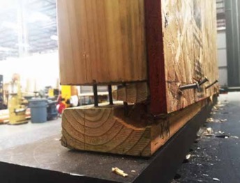
The 0.2-inch allowable limit prescribed in AC316 is important to a shearwall’s structural ability to transfer the necessary lateral loads through the structure below to the foundation level. This limit assures that the structural integrity of the nails and sill plates used to transfer the lateral loads through the shearwalls is not compromised during a seismic or wind event. Testing has shown that sill plates can crack when excessive deformation is observed in a shearwalls. Nails have also been observed to pull out during testing.  Additional information on this can be found here.

rod4
Sill Plates Cracked due to excessive uplift at ends of shearwall.
rods5
Nails pull out due to excessive uplift at ends of shearwall.

In AC316, 3 types of devices are listed.

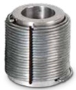
  • Compression-Controlled Shrinkage Compensating Device (CCSCD): This type of device is controlled by compression loading, where the rod passes uninterrupted through the device. Simpson Strong-Tie has several screw-type take-up devices, such as the Aluminum Take-Up Device (ATUD) and the Steel Take-Up Device (TUD), of this type.
rods6
ATUD (CCSCD)
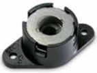
  • Tension-Controlled Shrinkage Compensating Device (TCSCD): This type of device is controlled by tension loading, where the rod is attached or engaged by the device and allows the rod to ratchet through as the wood shrinks. The Simpson Strong-Tie Ratcheting Take-Up Device (RTUD) is of this type.

rod7
RTUD (TCSCD)
  • Tension-controlled Shrinkage Compensating Coupling Device (TCSCCD): This type of device is controlled by tension loading that connects rods or anchors together. The Simpson Strong-Tie Coupling Take-Up Device (CTUD) is of this type.
CTUD (TCSCCD)
CTUD (TCSCCD)

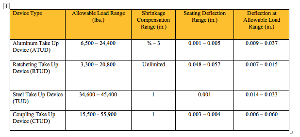
Each device type has unique features that are important in achieving the best performance for different conditions and loads. The following table is a summary of each device.

rods9The most cost-effective Simpson Strong-Tie shrinkage compensation device is the RTUD. This device has the smallest number of components and allows the rod unlimited travel through the device. It is ideal at the top level of a rod system run or where small rod diameters are used. Simpson Strong-Tie RTUDs can now accommodate 5/8″ (RTUD5) and ¾” (RTUD6) diameter rods.

How do you choose the best device for your projects? A Designer will have to consider the following during their design.

rod10
RTUD Assembly

Rod Tension (Overturning) Check:

  • Rods at each level designed to meet the cumulative overturning tension force per level
  • Standard and high-strength steel rods designed not to exceed tensile capacity as defined in AISC specification
    • Standard threaded rod based on 36 / 58 ksi (Fy/Fu)
    • High-strength Strong-Rod based on 92 / 120 ksi (Fy/Fu
    • H150 Strong-Rod based on 130 / 150 ksi (Fy/Fu)
  • Rod elongation (see below)

 Bearing Plate Check

  • Bearing plates designed to transfer incremental overturning force per level into the rod
  • Bearing stress on wood member limited in accordance with the NDS to provide proper bearing capacity and limit wood crushing
  • Bearing plate thickness has been sized to limit plate bending in order to provide full bearing on wood member

 Shrinkage Take-Up Device Check

  • Shrinkage take-up device is selected to accommodate estimated wood shrinkage to eliminate gaps in the system load path
  • Load capacity of the take-up device compared with incremental overturning force to ensure that load is transferred into rod
  • Shrinkage compensation device deflection is included in system displacement

 Movement/Deflection Check

  • System deformation is an integral design component impacting the selection of rods, bearing plates and shrinkage take-up devices
  • Rod elongation plus take-up device displacement is limited to a maximum of 0.2″ per level or as further limited by the requirements of the engineer or jurisdiction
  • Total system deformation reported for use in Δa term (total vertical elongation of wall anchorage system per NDS equation) when calculating shearwall deflection
  • Both seating increment (ΔR) and deflection at allowable load (ΔA) are included in the overall system movement. These are listed in the evaluation report ICC-ES ESR-2320 for take-up devices

 Optional Compression Post Design

  • Compression post design can be performed upon request along with the Strong-Rod System
  • Compression post design limited to buckling or bearing perpendicular to grain on wood plate
  • Anchorage design tools are available
  • Anchorage design information conforms to AC 318 anchorage provisions and Simpson Strong-Tie testing

In order to properly design a continuous rod tie-down system for your shearwall overturning restraint, all of the factors listed above will need to be taken into consideration.

A Designer can also contact Simpson Strong-Tie by going to www.strongtie.com/srs and filling out the online “Contact Us” page to have Simpson Strong-Tie design the continuous rod tie-down system for you. This design service does not cost you a dime. A few items will be required from the Designer in order for Simpson Strong-Tie to create a cost-effective rod run (it is recommended that on the Designer specify these in the construction documents):

  • There is a maximum system displacement of 0.2″ per level, which includes rod elongation and shrinkage compensation device deflection. Some jurisdictions may impose a smaller deflection limit.
  • Bearing plates and shrinkage compensation devices are required at every level.
  • Cumulative and incremental forces must be listed at each level in Allowable Stress Design (ASD) force levels.
  • Construction documents must include drawings and calculations proving that design requirements have been met. These drawings and calculations should be submitted to the Designer for review and the Authority Having Jurisdiction for approval.

More information can be obtained from our website at www.strongtie.com/srs, where a new design guide for the U.S., F-L-SRS15, and a new catalog for Canada, C-L-SRSCAN16, are available for download.

rod11
US Design Guide F-L-SRS15 and Canadian Catalog C-L-SRSCAN16

California Has Funding for $3,000 Grants for Home Retrofits

Are you an engineer working with California clients whose homes were built before 1979 on a raised foundation?

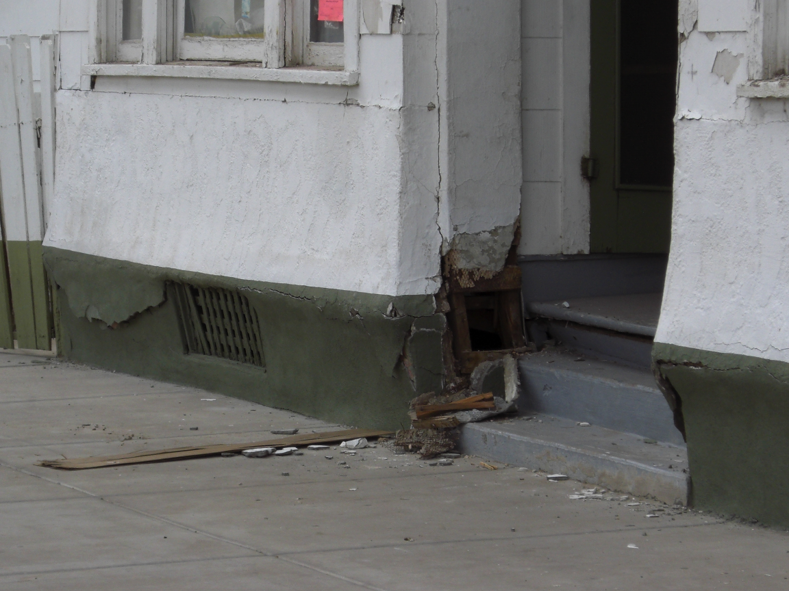
Evident earthquake damage
Earthquake damage sustained by a two-story building over a cripple wall system after the Mexicali Earthquake (M7.2).

If you are, these clients may be among the 1.2 million California homeowners eligible for a seismic home retrofit. The state of California has approved the continuation of an initiative known as Earthquake Bolt + Brace (EBB). In its second year, this program plans to make as many as 1,600 grants to selected homeowners, nearly three times the number given the previous year. The EBB grant program provides up to $3,000 to homeowners residing in more than 150 California zip codes. Check to see whether your clients live within one of these communities here.

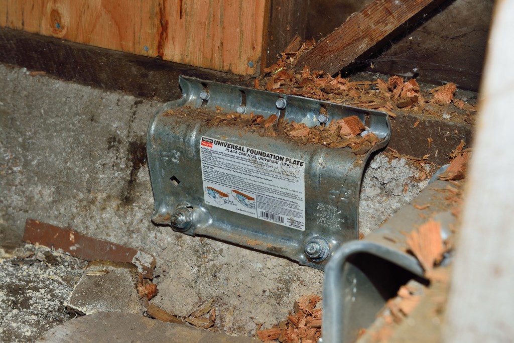
Simpson Strong-Tie has several different resources to assist you in helping your clients understand how to mitigate seismic risks to houses with raised foundations. The Seismic Retrofit Details sheet provides various ways to retrofit the cripple wall system using prescriptive methodologies, which can be adapted for engineered solutions. The picture below highlights the use of the Simpson Strong-Tie universal foundation plate (UFP) to attach the boltless sill plate of the cripple wall to the concrete stemwall. This simple step can help prevent the house from sliding off its foundation. The picture also reveals plywood sheathing used to reinforce the weak cripple wall system. Additional resources for retrofit can be found here.

earth2
Retrofit with UFP foundation plate in Napa, California

To help your clients better understand the impact these simple steps can have in preventing structural damage in an earthquake, click here to watch the story of a Napa business women who had purchased a structure with a raised foundation for her business and retrofitted it just prior to the 2014 M6.0 Napa earthquake, which caused considerable damage to many similar structures.

Let your clients know that the time to apply is very limited if they think they qualify for a retrofit grant. Registration for the 2016 EBB program ends on February 20. To register or learn more about the program, visit www.earthquakebracebolt.com.

When you finish a retrofit for one of your clients, we want to hear how it went. Let us know in the comments below.

Fiber Reinforced Polymer (FRP) Design Example

The following FRP Design example walks the reader through the typical process for designing an FRP strengthening solution for a concrete T-beam per ACI 440.2R Guide for the Design and Construction of Externally Bonded FRP Systems for Strengthening Concrete Structures.

One of the most important initial checks for an Engineer of Record is to confirm that the unstrengthened structure can support the load combination shown in Equation 5.5.1 in ACI 562 Code Requirements for Evaluation, Repair, and Rehabilitation of Concrete Buildings:

Eq. 5.5.1: (φRn)existing ≥ (1.2SDL + 0.5SLL)new

This check is to prevent a structural failure in case that the strengthening is damaged in an extraordinary event. If the structural element cannot pass this check, then external reinforcement is not recommended.

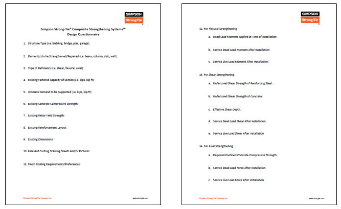
We have a Design Questionnaire where we ask Engineers of Record for more specific information related to the element to be strengthened:

doc1clone1

For this particular example, the following information was provided for the concrete T-beam.

1.  Structure Type (e.g., building, bridge, pier, garage):

  • 5-story commercial concrete building

2. Element(s) to be Strengthened/Repaired (e.g., beam, column, slab, wall):

  • Reinforced concrete beams

3. Type of Deficiency (e.g., shear, flexural, axial):

  • Flexural

4. Existing Factored Capacity of Section (e.g., kips, kip-ft):

  • 265 kip-ft

5. Ultimate Demand to be Supported (e.g., kips, kip-ft):

  • 320 kip-ft

6. Existing Concrete Compressive Strength:

  • 4,000 psi

7. Existing Rebar Yield Strength:

  • 60 ksi

8. Existing Reinforcement Layout:

  • 3 #7s 2.6875 inches from bottom of web to centroid of steel

9. Existing Dimensions:

  • 36 inches total beam height, 8 inches slab, 24 inches web width, 120 inches effective slab width

10. Relevant Existing Drawing Sheets and/or Pictures:

  • See attached

11. Finish Coating Requirements/Preferences:

  • None

12. For Flexural Strengthening:

  1. Dead Load Moment Applied at Time of Installation
    1. 60 kip-ft
  2. Service Dead Load Moment After Installation
    1. 80 kip-ft
  3. Service Live Load Moment After Installation
    1. 140 kip-ft

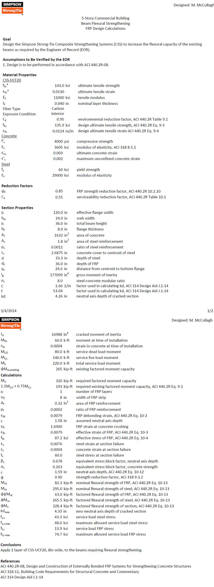
We then plug this information into our design program to come up with an FRP solution that meets the needs of the member:

masterdoc

For a beam that was at 83% of the capacity required for the new loading, we specified a simple, low-impact FRP solution to maintain clearances under the beams. If a traditional fix of adding cross-section to the beam had been specified instead, then additional concrete and rebar would need to be added to the beam, which would impact clearances under the beam and also increase the seismic weight of the building. The additional weight could also translate all the way through the building and even impact footing designs.

FRP can be used to increase the flexural strength up to 40% per ACI 440.

For your next retrofit project, please contact Simpson Strong-Tie to see if FRP would be an economical choice for strengthening your concrete or masonry element.

Add Simpson Strong-Tie to Your Design Team

Simpson Strong-Tie Composite Strengthening Systems™ is unlike choosing any other product we offer.

For your next retrofit project, please contact Simpson Strong-Tie to see if FRP would be an economical choice for strengthening your concrete or masonry element.


Specifying Self-Drilling Screws: “Standard” vs. “Engineered”

In my past life as a Design Engineer, when specifying a screw the size of the screw was the key feature that I considered. In my mind, a #10 screw performed better than #8, and a #12 was better than #10 and all #10 screws were the same. But that is not always true. Just as a shoe size or a dress size may not be exactly the same for all brands, a screw of the same size from different manufacturers may perform differently. The head type, head design, thread design (fine, coarse, thread angle, pitch), thread type (like box threads, buttress threads, unified, square) and drill point type (like #1, #3, #5 drill point) can influence the performance of a screw. When innovatively designed, a #10 engineered screw can meet or exceed the performance of a #12 or #14 screw in loads and drill time and could result in cost savings. You can use fewer screws, which would mean labor savings. For example, our newly designed XU34B1016 screw, which is a #10 screw with 16 threads per inch, a hex washer head and a #1 drill point, that performs better than a #14 standard screw in lighter gauge steels.

screws1

What Are Self-Drilling Tapping Screws?

Self-drilling tapping screws, or self-drilling screws, as the name implies, drill their own hole, eliminating the need for predrilling, and form or cut internal mating threads.  They are  relatively fast to  instal compared to bolts or welds. Unlike pins, they do not require a thick support material to be used. They can be used in very thin steel, such as 26 gauge, up to steel that is ½” thick. Self-drilling screws may be a perfect choice for most applications involving cold-formed steel (CFS). They are most commonly used for CFS connections: either attaching CFS to CFS, wood to CFS or CFS to wood. They are a logical choice when the other side of the connection or material is not accessible.

Most self-drilling screws are made of steel wire that meets the specification of ASTM A510 minimum grade 1018 material as specified in ASTM C1513 standard. Self-drilling screws are heat treated  to case harden then so that they meet the hardness, ductility, torsional strength and drill drive requirements as specified in ASTM C1513 standard.  ASTM C1513 refers to SAE J78 for the dimensional and performance requirements of self-drilling screws.

Screw Selection

While selecting the screw, you need to figure out the head type that works for the application. For example, a flat-head screw would be a good choice for wood-to-steel applications, but for steel-to-steel applications, a hex head or a pan head may be a better choice. Similarly, the length of the screw should be sufficient to fasten  the members of the connection together. According to Section D1.3 of AISI S200, the screw should be at least equal in length to the total thickness of the material including gaps with a minimum of three exposed threads. The length of the drill point is another important feature to consider. It should be long enough to drill through the entire thickness of the material before engaging the threads. This is because thread forming occurs with fewer revolutions than  the drilling process.   if the drill point length is not long enough, the screw threads can engage the connection material and the screw can bind and break.

screws2

Some drill points also have “wings” to  drill a hole in the material that is larger in diameter than the threaded shank. Screws with this kind of point are mainly used for wood-to-steel applications. The blog post by Jeff Ellis titled “Wings or No Wings” provides some useful insights for screws with wings when used in shearwall applications.

The Test Standards and Evaluation Criteria for Standard and Engineered Screws

Per Section D1 of AISI S200, screws used for steel-to-steel connections or sheathing-to-steel connections shall be in compliance with ASTM C1513 or an approved design or design standard.

For ASTM C1513–compliant screws (per AISI S100), Section E4 provides equations to calculate shear, pullout and pullover of screws used in steel-to-steel connections. It also provides safety and resistance factors for calculating allowable strength or design strength. These equations are based on the results of tests done worldwide and the many different types of screws used in the tests. As a result, these equations seem to have a great degree of conservatism.

As discussed earlier, many factors, such as the head type and washer diameter, thread profile, drill point type and length, installation torque and the installation method affect or influence the performance of a screw. In order to qualify the screws as ASTM C1513–compliant or better performing, manufacturers need to have their screws evaluated per Acceptance criteria for Tapping Screw Fasteners AC118 developed by International Code Council – Evaluation Service. The criteria have different requirements depending on whether the intention is to qualify as standard screws or proprietary screws.  For proprietary screws, connection shear, pullout and pullover tests are performed in accordance with the AISI S905 test method. The shear strength and tensile strength of the screw itself are evaluated per test standard AISI S904. The safety and resistance factors are calculated in accordance with Section F of AISI S100. The pictures below are some test set-ups per AISI S905 and AISI S904 test procedures.

screws3 screws4 screws5

Another important consideration is corrosion resistance. AC118 has a requirement for testing the fasteners for corrosion resistance in accordance with ASTM B117 for a minimum of 12 hours. The screws tested shall not show any white rust after 3 hours or any red rust after 12 hours of the test. At the same time, it is important to keep in mind  that  hardened screws are prone to hydrogen embrittlement and are not recommended for exterior or wet condition applications. Also, these screws are  not recommended for use with dissimilar metals.  If self-drilling screws are to be used in exterior environments, the screws need to be selectively heat treated to keep the core and surface hardness in a range that  reduces the susceptibility to hydrogen embrittlement. Other fastener options for exterior environments are stainless-steel screws.

This table shows are some of our screw offerings for CFS applications. Our stainless-screw options can be found in  Fastening Systems Catalog (C-F-14) or at www.strongtie.com.

screw6a

What are the screws that you most commonly specify? Share your screw preferences and your ideas on self-drilling screws in your comments below.

Don’t Buckle at the Knees: RCKW Testing

A previous blog post described how Simpson Strong-Tie tests and loadrates connectors used with cold-formed steel structural members per acceptance criteria ICC-ES AC261.

This week, I would like to describe how we test and determine engineering design values for RCKW, Rigid Connector Kneewall, in a CFS wall assembly and how the data can help designers perform engineering calculations accurately and efficiently.Continue Reading