This week’s post comes from Brad Erickson, who is the Engineering Manager for the Composite Strengthening Systems™ product line at our home office. Brad is a licensed civil and structural engineer in the State of California and has worked in the engineering field for more than 17 years. After graduating from Cal Poly, San Luis Obispo with a B.S. in Architectural Engineering, he worked for Watry Design, Inc. as an Associate Principal before coming to Simpson Strong-Tie. Brad is the Engineering Manager for Composite Strengthening Systems and his experience includes FRP design, masonry and both post-tensioned and conventional concrete design. While not at work, Brad enjoys spending time carting his three kids around to their competitive soccer games and practices.
Have you ever had a concrete or masonry design project where rebar was left out of a pour? Chances are, the answer is yes. Did you wish you could solve this problem by putting rebar on the outside of that element? That’s exactly what Simpson Strong-Tie Composite Strengthening Systems™ (CSS) can do for you and your project. In effect, composites act like external rebar for your concrete or masonry element. Composites can be used in similar configurations to rebar but are applied on the exterior surface of the element being strengthened.
The initial offering in our CSS line is our fiber-reinforced polymer (FRP) product group. An FRP composite is created by taking carbon or glass fabric and saturating it with a two-part epoxy which, when cured, creates the composite. Together, the weight of the fabric and the number of layers in the composite determine how much strength it will add to your concrete or masonry element.
Another form of FRP composite is a precured carbon laminate. The carbon fibers are saturated in the manufacturing facility and are attached to the structure using CSS-EP epoxy paste and filler, an epoxy with a peanut butter–like consistency. We also carry paste profilers (pictured below) that help contractors apply the proper amount of paste to a piece of precured laminate.
Of course, before any concrete or masonry reinforcement project can succeed, proper surface preparation is of the utmost importance. Without a good bond with the substrate, a composite will not be able to achieve the intended performance. Concrete voids must be repaired, cracks must be injected and sealed, and any deteriorated rebar must be cleaned and coated. Prior to composite placement, the surface of the substrate must be prepared to CSP-3 (concrete surface profile) in accordance with ICRI Guideline No. 310.2. Grinding and blasting are the most common surface-preparation techniques.
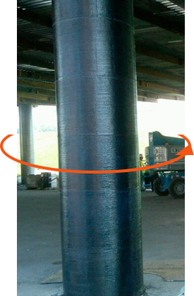
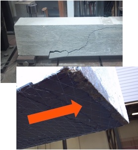
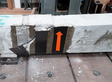
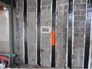
The following are just a few applications where composites can be used for concrete and/or masonry retrofits. The orange arrows show the direction of the fibers in the fabric – in other words, the direction in which the composite provides tension reinforcement.
This is a summary of the basics of composites and their installation on strengthening projects. As composites are not yet in the design codes in the United States, the American Concrete Institute has produced 440.2R-08: Guide for the Design and Construction of Externally Bonded FRP Systems for Strengthening Concrete Structures. This guide has numerous recommendations for using fiber-reinforced polymer systems to strengthen your concrete or masonry construction.
If you would like more information about FRP design, you can learn the best practices for fiber-reinforced polymer (FRP) strengthening design during a recorded webinar offered by Simpson Strong-Tie Professional Engineers. We look at FRP components, applications and installation. We also take you behind the scenes to share the evaluation process informing a flexural beam-strengthening design example and talk about the assistance and support Simpson Strong-Tie Engineering Services offers from initial project assessment to installation.
In this free webinar we dive into some very important considerations including the latest industry standards, material properties and key governing limits when designing with FRCM.
Continuing education credits will be offered for this webinar.
Participants can earn one professional development hour (PDH) or 0.1 continuing education unit (CEU).
For complete information regarding specific products suitable to your unique situation or condition, please visit strongtie.com/rps or call your local Simpson Strong-Tie RPS specialist.
Modern code-listed adhesive anchors offer high-strength connection solutions for a variety of applications. However, as in all construction projects, good product performance requires proper selection and installation. In this blog post, we will discuss the challenge of installation orientation and an accessory that can help installers more easily make proper adhesive anchor installations—the piston plug adhesive delivery system.
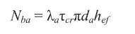
ACI 318-19 Chapter 17 (Anchoring to Concrete) calculations use a uniform bond stress model to calculate an adhesive anchor’s resistance to bond failure. According to this theory, an adhesive anchor is assumed to transfer applied loads into the concrete base material uniformly along its effective embedment depth, hef. The equation for an anchor’s basic bond strength (expressed in pounds of force) is simply the adhesive formulation’s bond strength per unit area ( λaτcr ) multiplied by the idealized cylindrical surface area of the insert that is in contact with the adhesive ( πdahef ):
(ACI 318-19, Eq. (17.6.5.2.1))
Although the model is a simplification of reality, the mathematical expression represents the core assumption that the adhesive is able to transfer stress completely along the entire depth of the anchorage. This is a key requirement in installation: Anchoring adhesives must be installed such that air entrapment and significant voids are prevented.
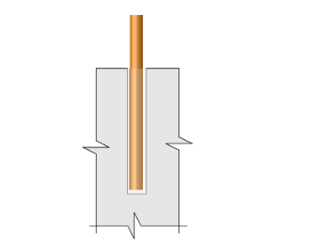
Downward installations (Figure 1) have historically presented relatively few challenges for adhesive injection in this regard. In such applications, gravity is helpful; the adhesive naturally flows to the bottom of the drilled hole while being dispensed from the cartridge through a static mixing nozzle. The installer maintains the open end of the nozzle below the free surface of the adhesive until the drilled hole is filled to the desired level. For deep holes, extension tubing is affixed to the open end of the nozzle to increase reach. This procedure avoids entrapping air bubbles in the adhesive material.
Figure 1 – Downward installation orientation
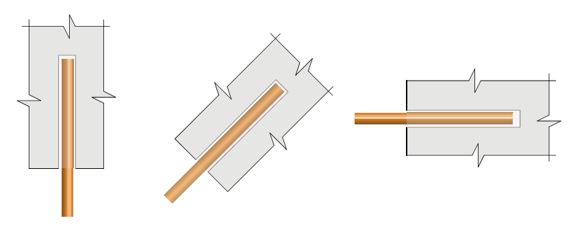
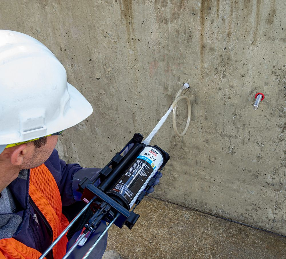
Installations into horizontal, upwardly inclined or overhead drilled holes (Figure 2) require more care on the part of adhesive anchor installers. Although the installation principle to avoid entrapping air is similar for these orientations, a key difference is that gravity does not help to keep the adhesive towards the “bottom” (deepest point) of the drilled hole. At worst, it can work against the installer when ambient temperatures may cause the adhesive to run out of the hole during injection. These adhesive anchor installations can be more difficult for an untrained installer and can slow the rate of work. This is one of the reasons that ACI 318-19 Section 26.13.3.2(e) requires continuous special inspection of adhesive anchor installations in these three orientations when the application is also intended to resist sustained loads.
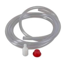
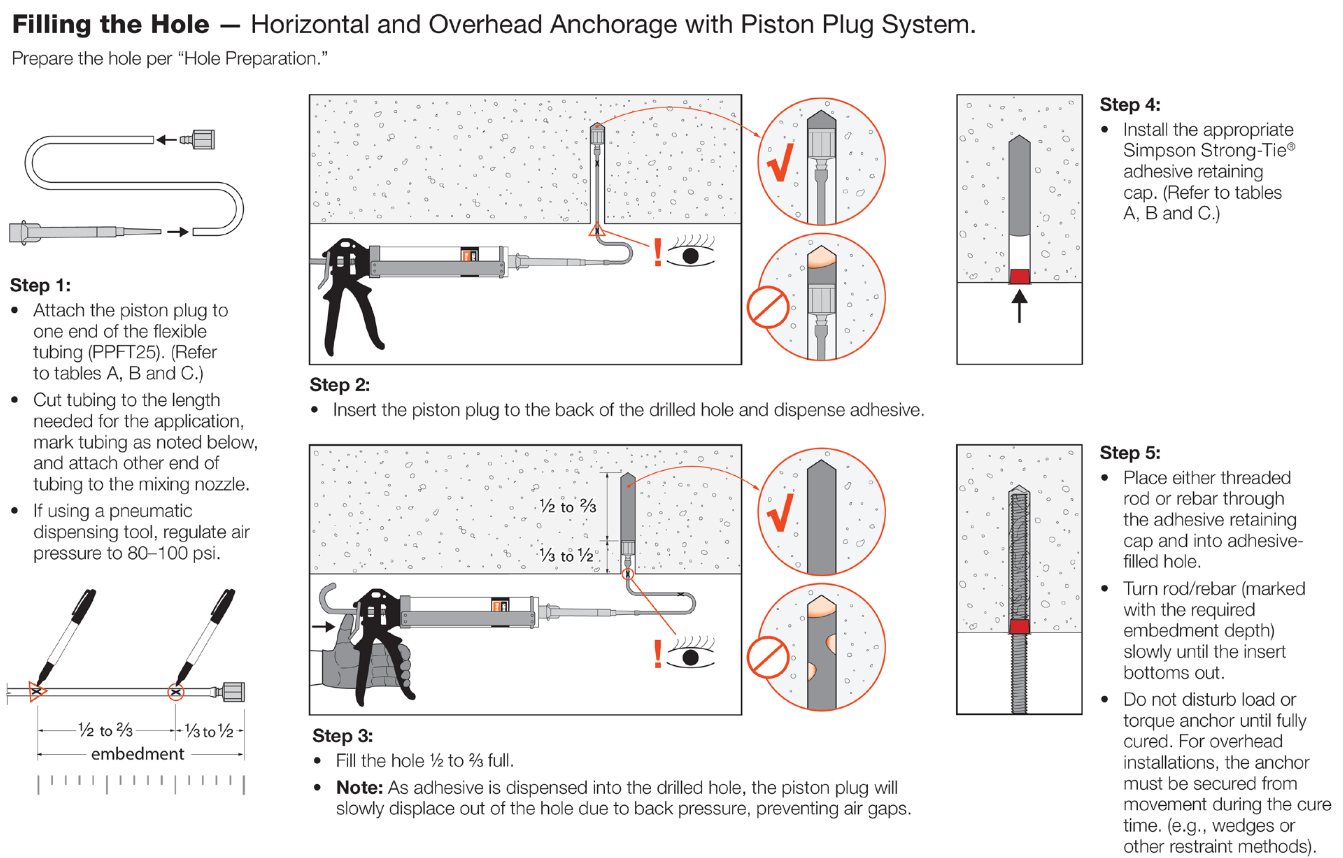
To aid the installer, Simpson Strong-Tie offers a piston plug adhesive delivery system (Figure 3). Consisting of pre-packaged flexible tubing, piston plugs and an adhesive retaining cap, this system allows installers to more easily and consistently make high-quality installations while completing their work efficiently. The installation sequence is provided in Figure 4.
Figure 3 – Piston plug delivery system
The system consists of three components:
Piston plug – The key component of the system, it is slightly smaller in diameter than the drilled hole. As the adhesive is dispensed into the drilled hole, the piston plug is displaced out of the hole by the advancing volume of the injected adhesive. The displacement creates a more positive feel for the installer to know where the free surface of the adhesive is.
Flexible tubing – For use with the piston plug to facilitate injection at the deepest point of the drilled hole.
Adhesive retaining cap – Provided to prevent adhesive material from flowing out of the drilled hole after dispensing and to provide a centering mechanism for the insert. For heavy inserts in overhead conditions, other means must be provided to carry the weight of the insert and prevent it from falling or becoming dislodged from the hole before the adhesive has fully cured.
Figure 4 – Installation sequence
What do you think about the piston plug adhesive delivery system? Let us know by posting a comment below.
If you’re one of the many engineers still sorting through the anchorage design provisions in ACI 318-19 Chapter 17, this blog will help clarify what’s required to achieve a ductile-performing anchorage. Current building codes (such as the 2024 IBC) reference ACI 318-19 Chapter 17 as the governing provisions for designing a wide variety of anchor types, including expansion, undercut, adhesive, screw, and cast-in-place anchors in concrete. This blog post will focus on Section 17.10.5.3(a) for anchors located in regions of moderate to high seismic risk. We’ll walk through what these requirements mean using a simple design example.
Ductility is a benefit in seismic design. A ductile anchor system is one that exhibits a meaningful degree of deformation before failure occurs. However, ductility is distinct from an equally important dimension called strength. Add strength, and a ductile steel element like the one shown in Figure 1 can now exhibit toughness. During a serious earthquake, a structural system with appreciable toughness (i.e., one that possesses both strength and ductility in sufficient degree) can be expected to absorb a tremendous amount of energy as the material plastically deforms and increases the likelihood that an outright failure won’t occur. Any visible deformations could help determine if repair is necessary.
Figure 1 – ½” mild steel threaded rod tensilely loaded to failure (starting stretch length = 8d)
Let’s start off with a simple example that will cover the essential requirements for achieving ductility and applies to any type of structural anchor used in concrete. We’ll arbitrarily choose a post-installed adhesive anchor. This type of anchor is very common in concrete construction and is used for making structural and nonstructural connections that include anchorage of sill plates and holdowns for shear walls, equipment, racks, architectural/mechanical/electrical components and, very frequently, rebar dowels for making section enlargements. We’ll assume the anchor is limited to resisting earthquake loading in tension only and is in seismic design category C – F. Section 17.10.5.2 requires that if the strength-level earthquake force exceeds 20% of the total factored load, that the anchor be designed in accordance with section 17.10.5.3 and 17.10.5.4. We will focus on achieving the ductility option, (a), of 17.10.5.3.
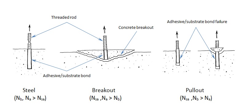
To understand anchor ductility we need to first identify the possible failure modes of an anchor. Figure 2 shows the three types of failure modes we can expect for an adhesive anchor located away from a free edge. These three failure modes generically apply to virtually any type of anchor (expansion, screw, cast-in-place or undercut). Breakout (Nb) and pullout (Na) are not considered ductile failure modes. Breakout failure (Nb) can occur very suddenly and behaves mostly linear elastic and consequently absorbs a relatively small amount of energy. After pullout failure (Na) has been initiated, the load/displacement behavior of the anchor can be unpredictable, and furthermore, no reliable mechanism exists for plastic deformation to take place. So we’re left with steel (Nsa). To achieve ductility, not only does the steel need to be made of a ductile material but the steel must govern out of the three failure modes. Additionally, the anchor system must be designed so that steel failure governs by a comfortable margin. Breakout and pullout can never control while the steel yields and plastically deforms. This is what is meant by meeting the ductility requirements of Chapter 17.
Figure 2 – Three possible failure modes for an adhesive anchor loaded in tension
Getting back to our design example, we have a single post-installed 5/8” diameter ASTM F1554 Gr. 36 threaded rod that’s embedded 12” deep, in a dry hole, in a concrete element that has a compressive strength of 2,500 psi. The concrete is 18” thick and we assume that the edge distance is large enough to be irrelevant. For this size anchor, the published characteristic bond strength is 743 psi. Anchor software calculations will produce the following information:
The governing design strength is compared to a demand or load combination that’s defined elsewhere in the code.
Here’s the question: Before proceeding with the remainder of this blog, judging by the design strength values shown above, should we consider this anchorage ductile? Your intuition might tell you that it’s not ductile. Why? Pullout clearly governs (i.e., steel does not). So it might come as a surprise to learn that this adhesive anchor actually is ductile!
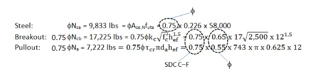
To understand why, we need to look at the nominal strength (not the design strength) of the different anchor failure modes. But first let’s examine the equations used to determine the design strength values above:
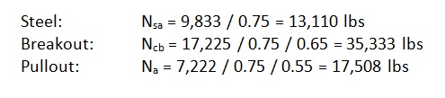
The above values incorporate the notation φ (“phi”) and a mandatory 0.75 reduction factor for nonductile failure modes (Ncb ,Na) for applications located in high seismic areas (seismic design category C–F). The φ factor is defined in section 17.5.3. However, manufacturers will list factors specific to their adhesive based on anchor testing. The mandatory 0.75 reduction comes from section 17.10.5.4 and is meant to account for any reduction associated with concrete damage during earthquake loading. The important thing to remember is that the nominal strength provides a better representation of the relative capacity of the different failure modes. Remove these reduction factors and we get the following:
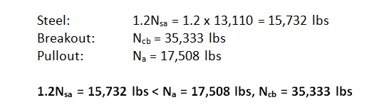
Now steel governs since it has the lowest strength. But we’re not done yet. Section 17.10.5.3.(a).(i) of Chapter 17 requires that the expected steel strength be used in design when checking for ductility. This is done by increasing the specified steel strength by 20%. This is to account for the fact that F1554 Gr. 36 threaded rod, for example, will probably have an ultimate tensile strength greater than the specified 58,000 psi. (Interestingly, the ultimate strength of the ½” threaded rod tested in Figure 1 is roughly 74 ksi, which is about 27% greater than 58,000 psi.) With this in mind, the next step would be to additionally meet section 17.10.5.3.(a).(ii) such that the following is met:
By increasing the steel strength by 20%, the nominal strength of the nonductile failure modes (Ncb ,Na) must be at least that much greater to help ensure that a ductile anchor system can be achieved. The values to compare finally become:
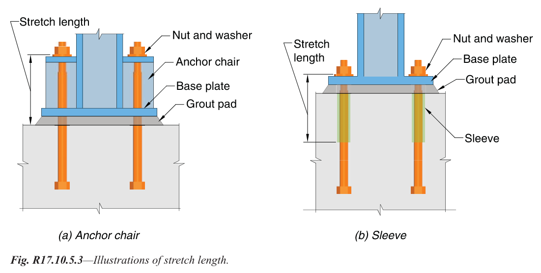
Now steel governs, but one more thing is required. As shown in Figure 3, Section 17.10.5.3.(a).(iii) of Chapter 17 also requires that the rod be made of ductile steel and have a stretch length of at least eight times the insert diameter (8d). Chapter 17 defines a ductile steel element as exhibiting an elongation of at least 14% and a reduction in area of at least 30%. ASTM F1554 meets this requirement for all three grades of steel (Grade 36, 55 and 105) with the exception of Grade 55 for anchor nominal sizes greater than 2”. Research has shown that a sufficient stretch length helps ensure that an anchor can experience significant yielding and plastic deformation during tensile loading. The threaded rod shown in Figure 1 was tested using a stretch length of 4” (8d). Lastly, section 17.10.5.3.(a).(iv) requires that the anchor be engineered to protect against buckling.
Figure 3 – Stretch length
Chapter 17 of ACI 318-19 doesn’t require that an anchor system behave ductilely. Three additional options exist for Designers in section 17.10.5.3. Option (b) allows for the design of an alternate failure mechanism that behaves ductilely. Designing a base plate (or support) that plastically hinges to exhibit ductile performance is one example. Option (c) involves a case where there’s a limit to how much load can be delivered to the anchor. Although option (c) under 17.10.5.3 falls under the tensile loading section of Chapter 17, the best example would apply to anchorage used to secure a wood sill plate or cold-formed steel track. We know from experiments that the wood crushes or the steel yields and locally buckles at a force less than the capacity of the concrete anchorage. Clearly energy is absorbed in the process. The most commonly used option is (d), which amplifies the earthquake load by Ωo. Ωo can be found in ASCE 7 – 16 for both structural and nonstructural components. The value of Ωo is typically taken to be equal to 2.5 (2.0 for storage racks) and is intended to make the anchor system behave linear elastically for the expected design-level earthquake demand.
These same options exist for shear loading cases. However, achieving system ductility through anchor steel is no longer an option for shear loading according to ACI 318 – 19, because the material probably won’t deform appreciably enough to be considered ductile.
While factors such as edge-distance and embedment-depth restrictions make achieving ductility difficult for post-installed anchors, it should come as some consolation that in many cases the Designer can achieve ductile performance for cast-in-place anchors loaded in tension through creative detailing of reinforcing steel (section 17.5.2.1) to eliminate breakout as a possible failure mode. This has been explored in some detail in two previous Simpson Strong-Tie blogs titled “Anchor Reinforcement for Concrete Podium Slabs” and “Steel Strong Wall Footings Just Got a Little Slimmer.”
Designing built-up columns? Now there’s a way to mechanically laminate multiple 2x members to meet the specifications in the National Design Specifications for wood. Simpson Strong-Tie evaluated Strong-Drive® SDW Truss-Ply screws for attaching multiple laminations with easier installation methods. With these screws, there’s no longer a need to nail from both sides of the column, or to use not-so-common 30d nails as specified in the NDS, or to pre-drill for bolts. Instead, installers can now install all the screws from one side of the built-up column, which provides time and cost savings.
This week is the 10th anniversary of Hurricane Katrina, and we have all seen articles on the lessons learned from the storm. Engineers learn something new from every storm. However, I think that Hurricane Katrina just gave us some very strong reminders of things we already knew.
Hurricane Katrina reminded us that hurricanes are flood events as well as high-wind events. And I don’t mean the flooding in New Orleans. No, I mean the flooding along the Gulf Coast from Louisiana to Florida.
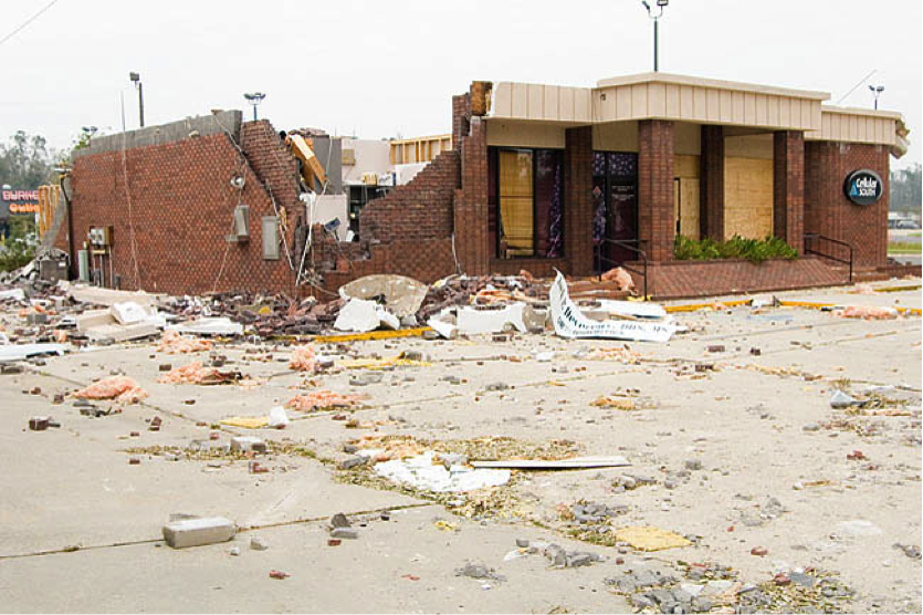
I witnessed the complete devastation of the Mississippi Gulf Coast from Waveland to Biloxi. Structures within the first few (and often many) blocks from the beach were simply flattened by water. Fortunately, these areas are coming back, but the structures being built there now bear little resemblance to the homes that graced the beach 10 years ago.
I remember my father-in-law having his new house built on the coast in Waveland more than 20 years ago. As a young engineer, I gave it the once over and noted that the builder had connected the roof framing to the top plate, but little else. I made some recommendations, such as continuing the connections down throughout the rest of the house to the foundation. The builder followed my suggestions and then presented my father-in-law with the bill “for your son-in-law the inspector.” He was happy to pay it. Nevertheless, although the house was wind resistant, it could not stand up to the rushing waters from Hurricane Katrina.
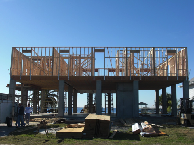
Katrina reminds us that the only way to get away from floods, other than not building near the water, is to elevate structures above them. Due to flood regulations, new houses along the Gulf Coast are now elevated high in the air, in the hope of avoiding flooding from future storms. Simpson Strong-Tie is proud to have developed some products during the last few years that make it easier to build structures elevated on pilings.
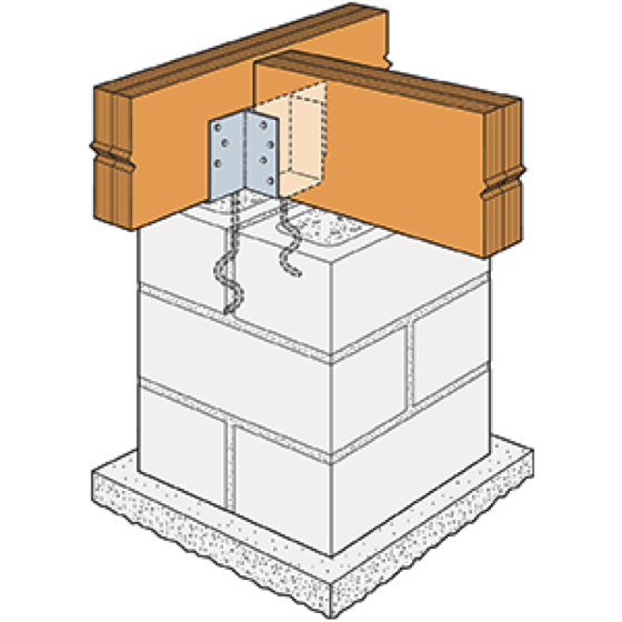
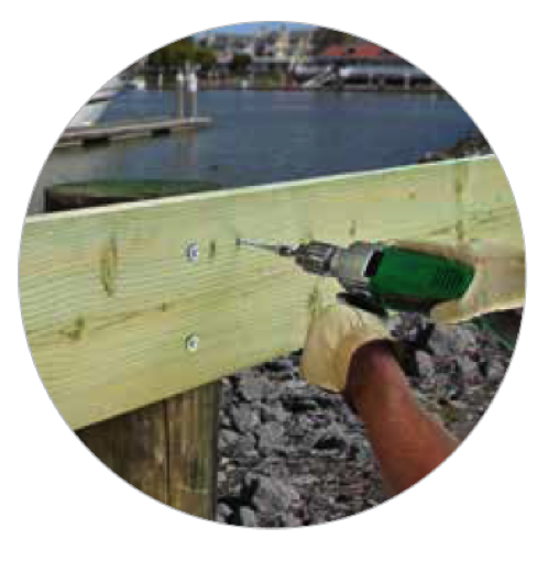
One such product is our CCQM column cap that strengthens the connection of support beams to masonry piers. Another is the Strong-Drive® SDWH Timber-Hex HDG structural screw, which is meant to replace through-bolts to make the connection of a beam to a wood piling easier and more reliable.
CCTQM InstallationElevated house built with CCQM Column Caps
SDWH TIMBER-HEX HDG Screw
Hurricane Katrina reminds us of the value of building codes. After the storm, the LSU Hurricane Center conducted a number of simulation studies on the effect of a direct, Katrina-like storm on the states of Louisiana, Mississippi and Alabama. The simulations were run on the existing stock of buildings, and then run again on the same stock of buildings, assuming that certain features that result from modern building codes were present. These features included shutters or impact-resistant windows, enhanced nailing of the roof deck to the roof framing, framing connected together with hurricane clips and straps to achieve a continuous load path. In addition, in the Louisiana study, a secondary water barrier over the joints in the roof sheathing was added.
The studies found that the decrease in wind damage from the simulated storms was astounding. In Louisiana, the study showed a 79% reduction in economic losses due to wind. In Alabama, the study revealed a 72% reduction in economic losses due to wind. The Gulf states seem to have received the message loud and clear. In the years following Hurricane Katrina, Louisiana adopted a statewide building code and Mississippi adopted a uniform building code for the four counties along the coast. Recently, Alabama has also adopted a statewide residential and energy code. But in general, building codes are still quite varied in coastal states. This report from the Insurance Institute for Business and Home Safety evaluates the effectiveness of building codes in coastal states.
Finally, Hurricane Katrina reminds those of us who do damage surveys that you need to know what you are getting into before you go. As soon as the storm hit and we saw the scope of the damage, four members of the Simpson Strong-Tie Engineering Department in our McKinney, Texas, office decided we needed to go see the damage first-hand before any repairs were made. So two days after the storm struck, off we went to Jackson, Mississippi. There, we rented two vans stocked up with food, water and fuel. Unfortunately, the fuel and the food/water ended up in separate vans. Before long, we were separated in traffic and could not communicate due to loss of cell signal.
Our team spent two days viewing the damage first-hand along the Louisiana and Mississippi coast, but spent a lot of time our last day trying to find some fuel so we could make it back to Jackson. I remember spending the night in a hotel without power full of storm victims, and then months later receiving the bill and being charged for a movie!
What do you remember from Hurricane Katrina? Let us know in the comments below.
Have you ever been at home during an earthquake and the lights turned off due to a loss of power? Imagine what it would be like to be in a hospital on an operating table during an earthquake or for a ceiling to fall on you while you are lying on your hospital bed.
A deck and porch study reported that 33% of deck failure-related injuries over the 5-year study period were attributed to guard or railing failures. While the importance of a deck guard is widely known, there was a significant omission from my May 2014 post on Wood-framed Deck Design Resources for Engineers regarding the design of deck guards.
A good starting point for information about wood-framed guard posts is a two-part article published in the October 2014 and January 2015 issues of Civil + Structural Engineer magazine. “Building Strong Guards, Part 1” provides an overview of typical wood-framed decks, the related code requirements and several examples that aim to demonstrate code-compliance through an analysis approach. The article discusses the difficulties in making an adequate connection at the bottom of a guard post, which involve countering the moment generated by the live load being applied at the top of the post. Other connections in a typical guard are not as difficult to design through analysis. This is due to common component geometries resulting in the rails and balusters/in-fill being simple-supported rather than cantilevered. “Building Strong Guards, Part 2” provides information on the testing approach to demonstrate code-compliance. Information about code requirements and testing criteria are included in the article as well.
Research and commentary from Virginia Tech on the performance of several tested guard post details for residential applications (36” guard height above decking) is featured in an article titled “Tested Guardrail Post Connections for Residential Decks” in the July 2007 issue of Structure magazine. Research showed that the common construction practice of attaching a 4×4 guard post to a 2x band joist with either ½” diameter lag screws or bolts, fell significantly below the 500 pound horizontal load target due to inadequate load transfer from the band joist into the surrounding deck floor framing. Ultimately, the research found that anchoring the post with a holdown installed horizontally provided enough leverage to meet the target load. The article also discussed the importance of testing to 500 pounds (which provides a safety factor of 2.5 over the 200-pound code live load), and the testing with a horizontal outward load to represent the worst-case safety scenario of a person falling away from the deck surface.
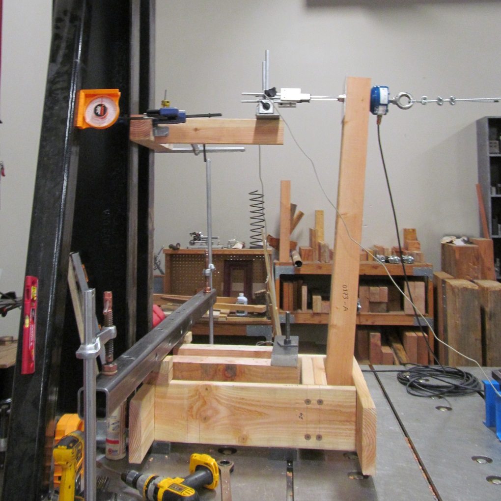
Simpson Strong-Tie has tested several connection options for a guard post at the typical 36” height, subjected to a horizontal outward load. Holdown solutions are included in our T-GRDRLPST22 technical bulletin. In response to recent industry interest, guard post details utilizing blocking and Strong-Drive® SDWS TIMBER screws have been developed (see picture below for a test view) and recently released in the engineering letter L-F-SDWSGRD15. The number of screws and the blocking shown are a reflection of the issue previously identified by the Virginia Tech researchers – an adequate load path must be provided to have sufficient support.
SDWS Detail C: Interior Post on Rim Joist between Joists, at 500-Pound Horizontal Test Target Load
Have you found any other resources that have been helpful in your guard post designs? Let us know by posting a comment.
Simpson Strong-Tie is sponsoring the 24th Short Course on Cold-Formed Steel Structures hosted by the Wei-Wen Yu Center for Cold-Formed Steel Structures (CCFSS). The course will be held on October 27-29, 2015 at the Drury Plaza Hotel at the Arch in St. Louis, MO.
This three-day course is for engineers who have limited or no experience designing with cold-formed steel (CFS), as well as those with experience who would like to expand their knowledge of cold-formed steel structural design. Lectures will be given by industry-recognized experts Roger LaBoube, Ph.D., P.E., and Sutton Stephens, Ph.D., P.E., S.E. The course is based on the 2012 AISI North American Specification for the Design of Cold-Formed Steel Structural Members and the 2012 North American Standards for Cold-Formed Steel Framing. Dr. Wei-Wen Yu’s book Cold-Formed Steel Design (4th Edition) will be a reference text.
The course will address such topics as design of wall studs, floor joists, purlins, girts, decks and panels. It is eligible for 2.4 Continuing Education Units (CEUs). Advance registration is requested by October 10, 2015. For more information and to register, click here.
While the contents of this blog are certainly not what Abraham Lincoln had in mind when he made the statement that I’m using to title this blog post, it does speak volumes to the pertinence of what will be discussed today. “Design by others” or some variation of this appears in many parts of Simpson Strong-Tie details.Continue Reading
While consideration of bracing is important for any structural element, this is especially true for thin, singly symmetric cold-formed steel (CFS) framing members such as wall studs. Without proper consideration of bracing, excessive buckling or even failure could occur. Bracing is required to resist buckling due to axial or out-of-plane lateral loads or a combination of the two.
There are two methods for bracing CFS studs as prescribed by the American Iron and Steel Institute (AISI) Committee on Framing Standards (COFS) S211 “North American Standard for Cold-Formed Steel Framing – Wall Stud Design” Section B1. One is sheathing braced design and the other is steel braced design.
Sheathing braced design has limitations, but it is a cost effective method of bracing studs since sheathing is typically attached to wall studs. This design method is based on an assumption that the sheathing connections to the stud are the bracing points and so it’s limited by the strength of the sheathing fastener to stud connection. Due to this limitation, the Designer has to use a steel braced design for most practical situations. AISI S211 prescribes a maximum nominal stud axial load for gypsum board sheathing with fasteners spaced no more than 12 inches on center. AISI S211 Section B1 and the Commentary discuss the design method and assumptions and demonstrate how to determine the sheathing bracing strength.
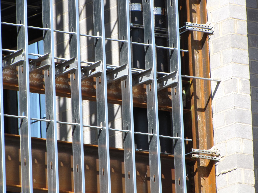
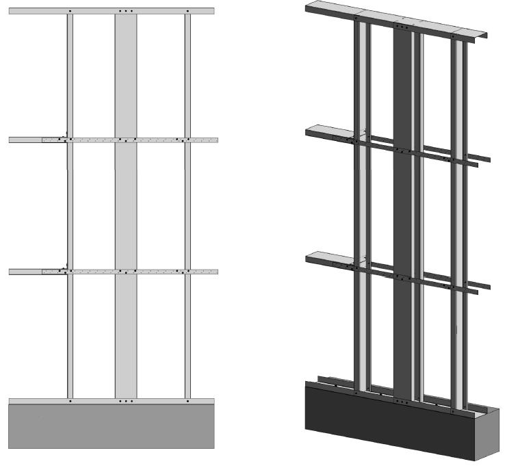
CFS Curtain Wall Stud Steel Clip and Bridging Bracing
Sheathing braced design requires that identical sheathing is used on each side of the wall stud, except the new AISI S240 standard Section B1.2.2.3 clarifies that for curtain wall studs it is permissible to have sheathing on one side and discrete bracing for the other flange not spaced further than 8 feet on center. The wall stud is connected to the top and bottom tracks or supporting members to provide lateral and torsional support and the construction drawings should note that the sheathing is a structural element. When the sheathing on either side is not identical, the Designer must assume the weaker of the two sheathings is attached to each side. In addition, the Designer is required to design the wall studs without the sheathing for the load combination 1.2D + (0.5L or 0.2S) + 0.2W as a consideration for construction loads of removed or ineffective sheathing. The Designer should neglect the rotational restraint of the sheathing when determining the wall stud flexural strength and is limited by the AISI S100 Section C5.1 interaction equations for designing a wall stud under combined axial and flexural loading.
Steel braced design may use the design methodology shown in AISI S211 or in AISI Committee on Specifications (COS) S100 “North American Specification for the Design of Cold-Formed Steel Structural Members.”
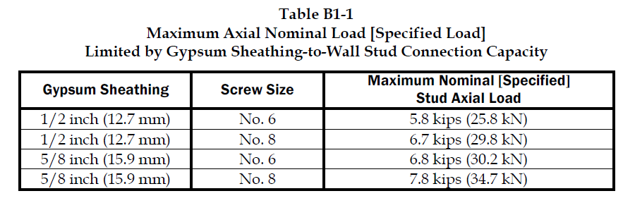
AISI S211 Table B1-1 Maximum Axial Nominal Load Limited by Gypsum Sheathing-to-Wall Stud Connection Capacity
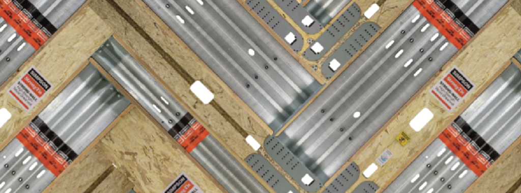
Steel braced design is typically either non-proprietary or proprietary “clip and bridging” bracing, or “flat strap and blocking” bracing periodically spaced along the height of the wall stud.
Steel braced design is a more practical bracing method for several reasons. First, during construction, wall studs go unsheathed for many months, but are subjected to significant construction loads.This is especially true for load-bearing, mid-rise structures. Second, some sheathing products, including gypsum wallboard, can be easily damaged and rendered ineffective if subjected to water or moisture. Third, much higher bracing loads can be achieved using mechanical bracing. IBC Section 2211.4 permits Designers to design steel bracing for axially loaded studs using AISI S100 or S211. However, S100-07 requires the brace to be designed to resist not only 1% of the stud nominal axial compressive strength (S100-12 changes this to 1% of the required compressive axial strength), but also requires a certain brace stiffness. S211 requires the Designer to design the bracing for 2% of the stud design compression force, and it does not have a stiffness requirement. . AISI S100 is silent regarding combined loading, but S211 provides guidance. S211 requires that, for combined loading, the Designer designs for the combined brace force determined using S100 Section D3.2.1 for the flexural load in the stud and either S100 or S211 for the axial load. In addition, the bracing force for stud bracing is accumulative as stated by S211 Commentary section B3. As a result, the periodic anchorage of the bracing to the structure such as strongbacks or diagonal strap bracing is required.
Some benefits and challenges of steel clip and bridging bracing include:
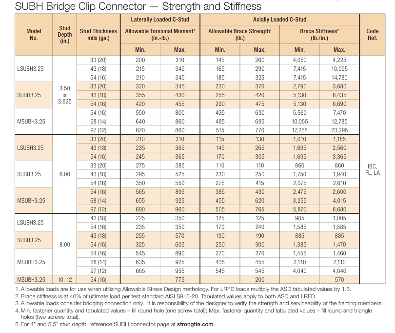
Proprietary solutions, such as the Simpson Strong-Tie SUBH bridging connector, can significantly reduce installed cost since many situations require only one screw at each connection.
Unlike strap bracing, u-channel bracing can be installed from one side of the wall.
U-channel bracing does not create build-up that can make drywall finishing more difficult.
Extra coordination may be required to ensure that u-channel bridging does not interfere with plumbing and electrical services that run vertically in the stud bay.
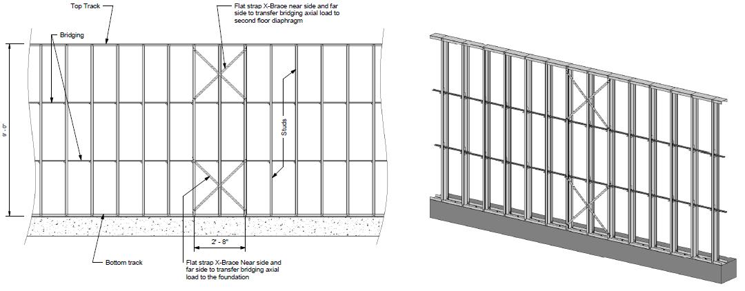
Bracing for axial loaded studs requires periodic anchorage to the structure, such as using strongbacks or diagonal strap bracing.
Bracing of laterally loaded studs does not require periodic anchorage since the system is in equilibrium as torsion in the stud is resisted by bridging (e.g., U-channel) bending.
Some benefits and challenges of steel flat strap and blocking bracing include:
May be installed at other locations than stud punchout.
Required to be installed on both sides of wall.
Bumps out sheathing.
Bracing for axial loaded studs requires periodic anchorage to structure, such as using strongbacks or diagonal strap bracing (same load direction in stud flanges).
Bracing for laterally loaded studs requires design of periodic blocking or periodic anchorage to the structure (opposite load direction in stud flanges).
There are several good examples Designers may reference when designing CFS wall stud bracing. They include AISI D110 Cold-Formed Steel Framing Design Guide that may be purchased from www.cfsei.org, SEAOC Structural/Seismic Design Manual Volume 2 Example 3 that may be purchased from www.seaoc.org, and the Simpson Strong-Tie wall stud steel bracing design example on page 147 of the C-CF-2026 CFS catalog.
Cold-formed steel framing is a versatile construction material, but Designers need to carefully consider the bracing requirements of the AISI specification and wall stud design standard. What cold-formed steel wall bracing challenges have you encountered and what were your solutions?
We use cookies on this site to enhance your user experience. By clicking "I AGREE" below, you are giving your consent for us to set cookies. Privacy PolicyI AGREE
Privacy & Cookies Policy
Privacy Overview
This website uses cookies to improve your experience while you navigate through the website. Out of these cookies, the cookies that are categorized as necessary are stored on your browser as they are essential for the working of basic functionalities of the website. We also use third-party cookies that help us analyze and understand how you use this website. These cookies will be stored in your browser only with your consent. You also have the option to opt-out of these cookies. But opting out of some of these cookies may have an effect on your browsing experience.
Necessary cookies are absolutely essential for the website to function properly. This category only includes cookies that ensures basic functionalities and security features of the website. These cookies do not store any personal information.
Any cookies that may not be particularly necessary for the website to function and is used specifically to collect user personal data via analytics, ads, other embedded contents are termed as non-necessary cookies. It is mandatory to procure user consent prior to running these cookies on your website.


 Another form of FRP composite is a precured carbon laminate. The carbon fibers are saturated in the manufacturing facility and are attached to the structure using CSS-EP epoxy paste and filler, an epoxy with a peanut butter–like consistency. We also carry paste profilers (pictured below) that help contractors apply the proper amount of paste to a piece of precured laminate.
 Of course, before any concrete or masonry reinforcement project can succeed, proper surface preparation is of the utmost importance. Without a good bond with the substrate, a composite will not be able to achieve the intended performance. Concrete voids must be repaired, cracks must be injected and sealed, and any deteriorated rebar must be cleaned and coated. Prior to composite placement, the surface of the substrate must be prepared to CSP-3 (concrete surface profile) in accordance with ICRI Guideline No. 310.2. Grinding and blasting are the most common surface-preparation techniques.
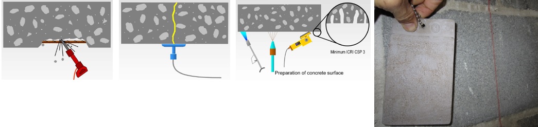 The following are just a few applications where composites can be used for concrete and/or masonry retrofits. The orange arrows show the direction of the fibers in the fabric – in other words, the direction in which the composite provides tension reinforcement.