Experiential learning — has it happened to you? Certainly it has, because experiential learning is learning derived from experience. It happens in everyday life, in engineering and in product development, too. For example, experience has taught us that after a product is launched, our customers will find applications for the product that were never expected or listed in the product brief. Also, experience has shown us that larger fasteners tend to be placed in applications that have greater structural and safety demands.
When the larger Deck-Drive™ DWP screws were manufactured, we decided that they should be marketed as “load-rated” screws because they were big enough to support physically large parts and would be expected to provide structural load resistance.
So what is a “load-rated” screw? To Simpson Strong-Tie, a load-rated screw is a threaded fastener that has controlled dimensions and physical properties, as well as validated connection properties. Load-rated fasteners are also subject to the same quality inspection that would occur if they were undergoing an evaluation report.
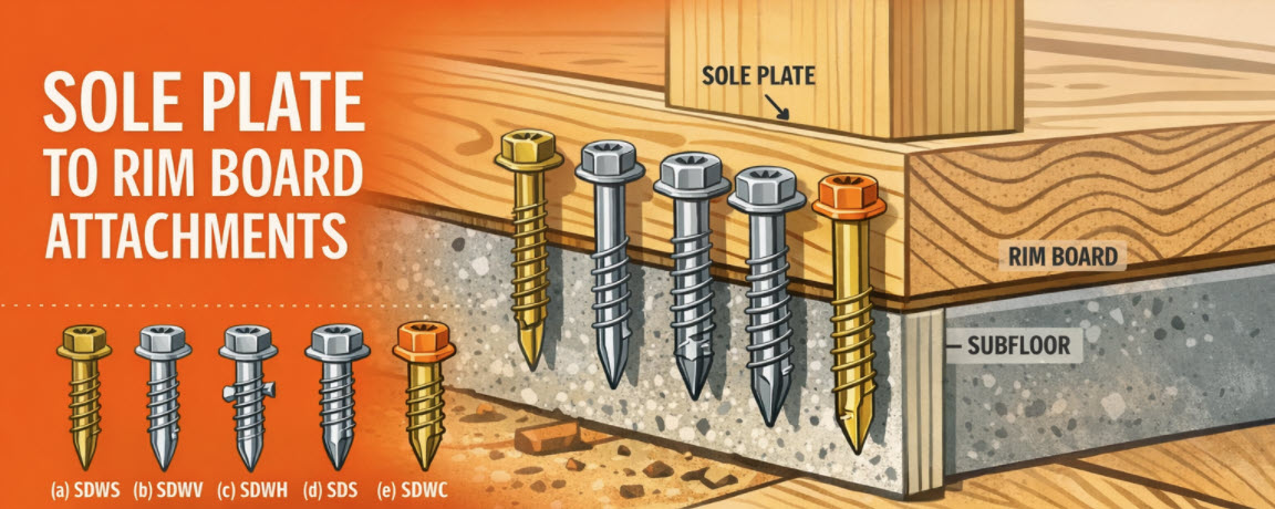
For many years, builders have struggled with the awkward sole-plate-to-rim-board attachment. They often install a few nails and call it good, resulting in a connection with significantly less capacity than needed. This connection is critical to ensure that seismic and wind loads are adequately transferred to the lateral-force-resisting system. With screws becoming much more common in construction, we saw an opportunity to address this problem.
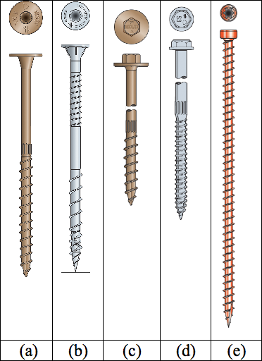
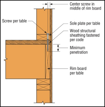
We offer a variety of structural wood screws that have shank diameters ranging from 0.135″ to 0.244″. They form our Strong-Drive® line of structural fasteners. The Simpson Strong-Tie® Strong-Drive SDWC Truss, SDWH Timber-Hex, SDWS Timber, SDWV Sole-to-Rim and SDS Heavy-Duty Connector structural wood screws as shown in Figure 1 can be used to attach sole plates to a rim board as shown in Figure 2. These screws provide structural integrity in the wall-to-floor connection.
The sole-to-rim connection is considered a dry service location. When the sole plate and the rim are both clean wood (not treated), then any of the screws can be used as long as they meet the design loads. However, if one or both members of the connection are treated with fire retardants or preservatives, then you must use the SDWS Timber screw, SDWH Timber-Hex screw or SDS Heavy-Duty Connector screw. The SDWS, SDWH and SDS screws all have corrosion-resistance ratings in their evaluation reports.
Figure 1. Simpson Strong-Tie Strong-Drive screws for fastening the sole-to-rim connection: (a) SDWS Timber screw, (b) SDWV Sole-to-Rim screw, (c) SDWH Timber-Hex screw, (d) SDS Heavy-Duty Connector screw, (e) SDWC Truss screw.Figure 2. The load rating for the sole-to-rim connection is for transfer of loads parallel to the sole plate to the rim. This is a dry service condition.
The Strong-Drive SDWV structural wood screw has the smallest diameter among these screws. The SDWV is 4″ long and has a 0.135″- diameter shank, and a large 0.400″-diameter ribbed-head with a deep six-lobe recess to provide clean countersinking. It is designed to be fast driving with very low torque. The Strong-Drive SDWS offers one of the larger diameters. It has a 0.220″-diameter shank and is offered in lengths of 4″, 5″ and 6″. It has a large 0.750″-diameter washer head which provides maximum bearing area. Longer screws allow designers to meet the minimum penetration requirement into a rim board, when the sole plate is a 3x or a double 2x member.
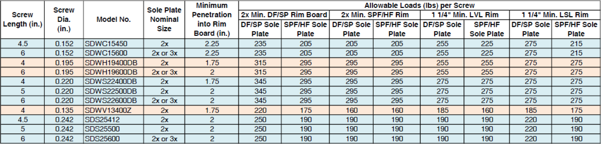
We have tested various combinations of sole plates, floor sheathing, and rim boards. Typical test assemblies were built and tested with two (2) Strong-Drive® screws spaced at either 3″ or 6″. Results were analyzed per ICC-ES AC233, “Acceptance Criteria for Alternate Dowel-type Threaded Fasteners.” The allowable loads listed in Table 1 are based on the average ultimate test load of at least 10 tests, divided by a safety factor of 5.0, and are rated per single fastener. The results of these tests can be found in the engineering letter L-F-SOLRMSCRW16.
The evaluated sole plates include southern pine (SP), Douglas fir-larch (DF), hem-fir (HF), and spruce-pine-fir (SPF) in single 2x, 3x or double 2x configurations. Floor sheathing thicknesses are allowed up to 1 1/8″ thick. Rim boards can be LVL or LSL structural composite lumber or DF, SP, HF or SPF sawn lumber. The load rating also assumes that the floor sheathing is fastened separately and per code.
See strongtie.com for evaluation report information if it is needed.
As a Designer, you can specify any of these Strong-Drive screws that fit your design requirements. Please visit our website and download L-F-SOLRMSCRW16 for more details.
The parts won’t hold themselves up. They have to be fastened in place.
The previous blog in the How to Pick a Connector Series by Randy Shackelford, on “ Selecting a Joist Hanger,” covered the available Simpson Strong-Tie joist hanger options and how to pick a hanger for your design. This week’s blog focuses on the fasteners recommended for various wood connectors.
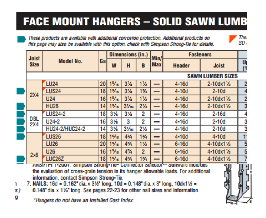
For straps, holdowns and other connectors, the first step is to specify a product that meets the load and corrosion resistance requirements. Then, specify fastening that is appropriate. The Wood Construction Connectors catalog, C-C-2026, offers fastener information for every Simpson Strong-Tie connector used in wood construction. If you specify the type and number of fasteners and install them as shown in the catalog, then your installation will get full design values. Many connectors are designed to be installed with either nails or Strong-Drive® SD Connector screws. Some products must be installed with Strong-Drive SDS Heavy-Duty Connector screws. Figure 1 is a snip from page 114 of catalog C-C-2026. Here the face-mount hanger table gives the size and number of nails to be installed in the header and the joist, and the table note defines the nail size terminology. Let’s take a look at the various fasteners used for Simpson Strong-Tie connectors of all varieties.
Figure 1. A snip from the face-mount hangers table showing the size and number of nails to be used in the header and joist. The footnote defines the nail sizes in the table.
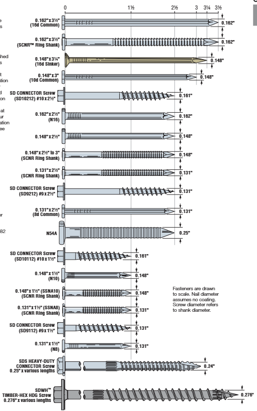
Figure 2 shows a scale view of almost all of the fasteners used with connectors. You can find this illustration in the Fastening Systems catalog, C-F-2025, and the Wood Construction Connectors catalog, C-C-2026. However, we are continually designing, evaluating and adding new fasteners to use with our connectors. Check our website for the latest and greatest.
Figure 2. Fastener types and sizes specified for Simpson Strong-Tie connectors.
Keep in mind some generalities that are to be considered in every connector fastener specification.
Type and size – Be sure to specify the correct type of fastener and size; for nails, that means diameter and length.
Do not mix fasteners – Do not combine nails and screws in the same connector unless specifically allowed to do so in the load table.
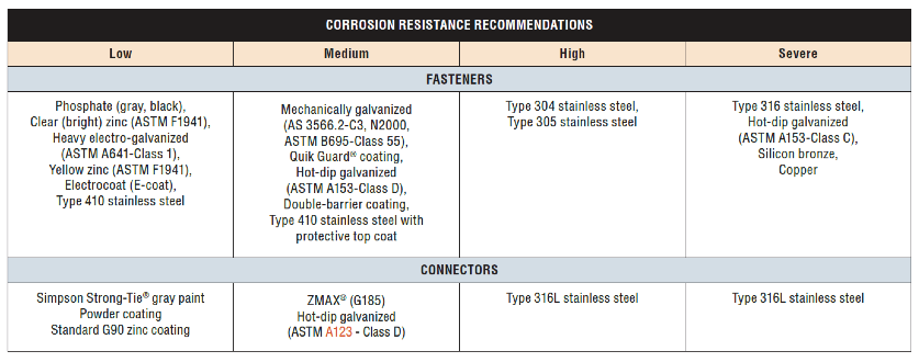
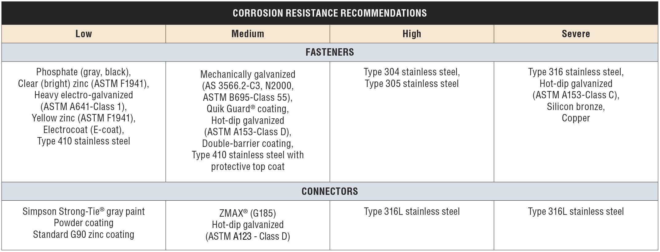
Corrosion resistance – Consider environmental corrosion and galvanic corrosion. For environmental corrosion, specify fasteners that have corrosion resistance similar to the connector; for galvanic corrosion, the fasteners and connector should be galvanically compatible. Figure 3 shows the corrosion resistance recommendations for fasteners and connectors.
Figure 3. Corrosion resistance recommendations.
NAILS
Nail terminology is messy. In a Structure Magazine article (July 2016), the author made the point that nail specifications are frequently misinterpreted (or overlooked), and as a result the built system does not have the intended design capacity. In general construction vernacular, specification by penny size identifies only the length. For example, a “10d” specification could be interpreted to mean 10d common – 0.148″ x 3″, 10d box – 0.128″ x 3″, 10d sinker – 0.120″ x 2.875″, or the 10d x 2.5″ – 0.148″ x 2.5″. See NDS-24, Appendix L, Table L4 for the length, nail diameter and head diameter of Common, Box, and Sinker steel wire nails. What if the face-mount hanger needed 0.148”x3” nails to achieve full load, but the face-mount hanger was installed with 0.148″ x2.5″? In this case, the nail substitution causes a reduction in load capacity of 15%. The load capacity losses would be even greater if 10d sinker or 10d box nails were used. The load adjustment factors for nail substitutions used with face- mount hangers and straight straps are shown in Table 3.
Simpson Strong-Tie nail terminology further complicates nail specification because, in Strong-Tie lingo, the penny reference is to diameter (not to length). This is further reason to write nail specifications in terms of diameter and length.
The best way to prevent mistakes is to specify nails by both length AND diameter.
There are two types of connector nails available, the Strong-Drive® SCNR Ring-Shank Connector nail and the Strong-Drive SCN Smooth-Shank Connector nail. SCN stands for Structural Connector Nails. R would refer to ring- shank nails. Currently most ring-shank connector nails are available in Type 316 stainless steel. Reasons for this are discussed here. The smooth-shank nails are made of carbon steel and either have a hot-dip galvanized (HDG) finish meeting the specifications of ASTM A153, Class D, or have a bright finish. Stainless-steel ring-shank nails are recommended for stainless-steel connectors. Use hot-dip galvanized nails with ZMAX® and HDG connectors. See Load tables for the nail properties.
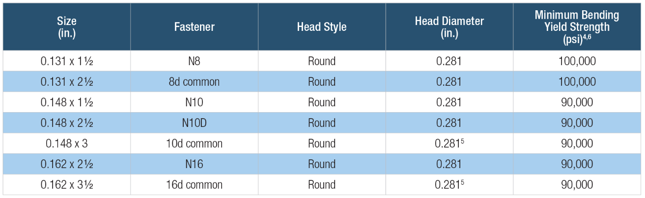
Table 1. Simpson Strong-Tie® connector nail terminology decoder. The penny size refers to diameter and “N” indicates a short nail.
Simpson Strong-Tie connector nail specifications include common nails, sinker nails and short nails. Nails used in connectors should always have a full round head and meet the bending yield requirements of ASTM F1667, Table S1. Nails can be driven with a hammer or power-driven. Table 2 shows the Strong-Tie connector nails by catalog name, size and model number.
Table 2. Simpson Strong-Tie® Strong-Drive® SCN and SCNR Connector nails. HDG is hot-dip galvanized per ASTM A153, Class D; EG is electro-galvanized per ASTM B641, Class 1; SS is Type 316 stainless steel; “A” indicates ring-shank. These are collated for power-tool nailing in paper tape (PT).
Remember that connector double-shear nailing should always use full-length common nails. Do not use shorter nails in double-shear conditions.
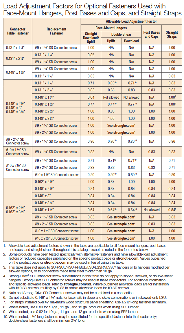
Table 3 is snipped from the Fastening Systems catalog, and it shows load adjustment factors for optional fasteners used in face-mount hangers and straps.
Page 26 of Connector catalog C-C-2026
SD Screws
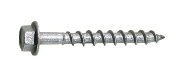
Figure 4. SD9112 CONNECTOR Screw.
Almost 150 Simpson Strong-Tie connectors can be installed with Simpson Strong-Tie Strong-Drive® SD Connector screws (Figure 4). The shanks of the SD Connector screws are designed to match the fastener holes in Simpson Strong-tie connectors. The screw features, dimensions, strengths and allowable single-fastener properties are given in ICC-ES ESR-3046, and the SD screws have been qualified for use in engineered wood products. See ICC-ES ESR-3096 for code-approved connectors installed with SD screws.
SD screws can make connector and strap installation easier and can also provide some resistance that is needed beyond what might be offered by nails. Ease of installation is sometimes an issue in tight places where it might be much easier to use a screw-driving tool rather than a hammer or a power nailer. Some installations are improved by using screws instead of nails, especially where pulling away from the mounting member is a possible failure mode. For example, joist hangers for a deck need withdrawal resistance to help keep the deck tightly connected to the ledger.
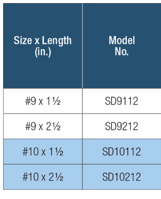
SD screws are available in four sizes as shown in Table 4 below. These screws are mechanically galvanized per ASTM B695, Class 55, and have corrosion-resistance qualifications for use in chemically treated wood for Exposure Conditions 1 and 3 per ICC-ES AC257, which is the acceptance criterion for Corrosion-Resistant Fasteners and Evaluation of Corrosion Effects of Wood Treatment Chemicals. See ICC-ES ESR-3046 for corrosion resistance details. Visit SD Screws in Connectors for a complete list of connectors that can be installed with SD screws.
Table 4. SD Connector Screws.
Here are a few specification and construction tips for SD screws:
SD10 screws replace 16d common and N16 nails in face-mount hangers and straps.
SD9 screws replace 8d and 10d common and 1-1/2″ size nails and 16d sinker nails (all nails 0.148″ and 0.131″ diameter) in face-mount hangers and straps.
When SD screws are to be an alternative to nails, specify and use only SD screws. Other types of screws shall not be substituted.
SD screws are required to be installed by turning. Do not drive them with a hammer or palm nailer!
SD screws and nails cannot be mixed in the same connector.
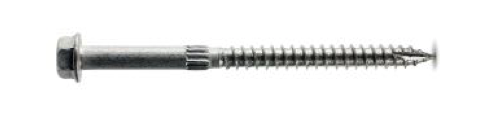
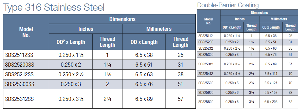
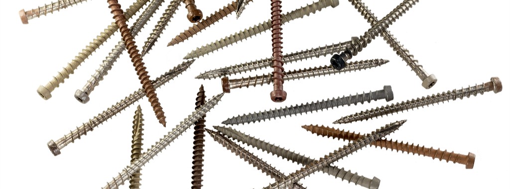
The Simpson Strong-Tie Strong Drive® SDS Heavy-Duty Connector screws are 1/4″ screws with a hex washer head (Figure 5). They are available in nine lengths. Table 5 shows the available SDS screws. SDS Screws are available with a double-barrier coating or in Type 316 stainless steel. These screws can be installed with no predrilling and have been extensively tested in various applications. SDS screws can be used for both interior and exterior applications. See ICC-ES ESR-2236 for dimensions, mechanical properties and single-fastener allowable properties. As shown in the evaluation report, SDS screws are also qualified for use in chemically treated wood. See the evaluation report for particulars. SDS screws also have been qualified for use in engineered wood products.
Table 5. SDS Heavy-Duty Connector Screws.
If you need more information about the nails and screws recommended for use with Simpson Strong-Tie connectors, visit strongtie.comand see the appropriate catalog, flier or engineering letter. Remember, your choice of fasteners affects the load capacity of your connections.
Let us know if you have any comments on Simpson Strong-Tie fasteners for straps, holdowns and other connectors.
Who likes red rust? No one I know! How do we avoid corroding of fasteners? Corrosion can be controlled or eliminated by providing a corrosion-resistant base metal or a protective finish or coating that is capable of withstanding the exposure environment. When fasteners get corroded, they not only look bad from outside but can also lose their load capacity. To ensure continued fastener performance, we have to control for corrosion. This blog focuses on evaluating the corrosion resistance of the fasteners.
What does the building code specify?
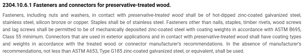
For use in preservative-treated wood, the IBC-2024 specifies fasteners that are hot-dipped galvanized, stainless steel, silicon bronze or copper. Section 2304.10.6.1 of IBC-2024 (Figure 1) covers fastener and connector requirements for preservative-treated wood (chemically treated wood). While chemically treated wood is part of the corrosion hazard, it is not the whole corrosion hazard. Weather exposure, airborne chemicals and other environmental conditions contribute to the corrosion hazard for metal hardware. In addition, the main issue with the code-referenced requirements for fasteners and connectors used with preservative-treated wood is that not all preservative treatments deliver the same corrosion hazard and not all fasteners can be hot-dip galvanized.
Figure 1: Section 2304.10.6.1 IBC-2024.
What if we want to use an alternative base material or coating for fasteners?
How do we evaluate the corrosion resistance of the alternative material or coating? The codes do not provide test methods to evaluate alternate materials and coatings. However, the International Code Council–Evaluation Service (ICC-ES) developed acceptance criteria to evaluate alternative coatings that are not code recognized for use in different environments. The purpose of acceptance criteria ICC-ES AC257, Acceptance Criteria for Corrosion-Resistant Fasteners and Evaluation of Corrosion Effects of Wood Treatment Chemicals, is twofold: (1) to establish requirements for evaluating the corrosion resistance of fasteners that are exposed to wood-treatment chemicals, weather and salt corrosion in coastal areas; and (2) to evaluate the corrosion effects of wood-treatment chemicals. In this blog post, we will concentrate on the evaluation of corrosion resistance of fasteners. The criteria provide a protocol to evaluate the corrosion resistance of fasteners where hot-dip galvanized fasteners serve as a performance benchmark. The fasteners evaluated by these criteria are nails or screws that are exposed directly to wood-treatment chemicals and that may be exposed to one or more corrosion accelerators like high humidity, elevated temperatures, high moisture or salt exposure.
The fasteners may be evaluated for any of the four exposure conditions:
Exposure Condition 1 with high humidity. This test can be used to evaluate fasteners that could be exposed to high humidity. Typical applications that fall under this category are treated wood in dry-use applications.
Exposure Condition 2 with untreated wood and salt water. This test can be used to evaluate fasteners that are above ground but exposed to coastal salt exposure.
Exposure Condition 3 with chemically treated wood and moisture. This test covers all the general construction applications.
Exposure Condition 4 with chemically treated wood and salt water. Typical applications include coastal construction applications.
Depending on the exposure condition being used for fastener evaluation, the fasteners are installed in wood that could be either chemically treated or untreated. Then the wood and the fasteners are placed in the chamber and artificially exposed to the evaluation environment. Two types of test procedures are to be completed for exposure condition 2 through 4. The purpose of these tests is not to predict the corrosion resistance of the coatings being evaluated, but to compare them to fasteners with the benchmark coating (ASTM A153, Class D) in side-by-side exposure to the accelerated corrosion environment.
ASTM B117 Continuous Salt-Spray Test
ASTM B117 is a continuous salt-spray test. For Exposure Condition 3, distilled water is used instead of salt water. The fasteners are continuously exposed to either moisture or salt spray in this test, and the test is run for about 1,440 hours after which the fasteners are evaluated for corrosion. This is an accelerated corrosion test that exposes the fasteners to a corrosive attack so the corrosion resistance of the coatings can be compared to a benchmark coating (hot-dip galvanized).
ASTM G85, Annex A5
The second test is ASTM G85, Annex A5 which is a cyclic test with alternate wet and dry cycles. The cycles are 1-hour dry-off and 1-hour fog alternatively. This is a cyclic accelerated corrosion test and relates more closely to real long-term exposure. This test is more representative of the actual environment than the continuous salt-spray test. As in the ASTM B117 test, the fasteners along with the wood are exposed to 1,440 hours, after which the corrosion on the fasteners is evaluated and compared to fasteners with the benchmark coating.
Test Method and Evaluation
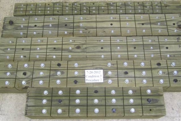
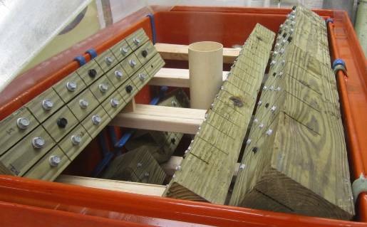
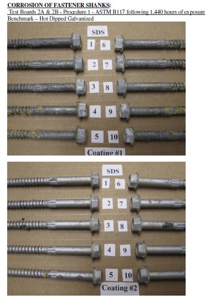
The test process involves installing 10 benchmark fasteners along with 10 fasteners for each alternative coating being evaluated. The fasteners are arranged in the wood with a spacing of 12 times the fastener diameter between the fasteners. A kerf cut is provided in the wood between the fasteners to isolate the fasteners as shown in Figure 2 and to ensure elevated moisture content in the wood surrounding the fastener shank. The moisture and retention levels of the wood are measured, and the fasteners are then installed in the chamber as shown in Figure 3 and exposed to the designated condition. The test is run for the period specified, after which the fasteners are removed, cleaned and compared to the benchmark for corrosion evaluation. Figure 4 shows the wood and fastener heads after 1,440 hours (60 days). The heads and shanks of the fasteners are visually graded for corrosion in accordance with ASTM D610. If the alternate coating performs equivalent to or better than the benchmark coating — that is, if the corrosion is no greater than in the benchmark — then the coating has passed the test and can be used as an alternative to the code-approved coating. Figure 5 shows the benchmark and alternative fasteners that are removed from the chamber after 1,440 hours.
As you can see, the alternative coatings have to go through extended and rigorous testing and evaluation as part of the approval process before being specified for any of the fasteners. Some alternative coatings provide even better corrosion resistance than the code recognized options. Sometimes, also, the thickness of these alternative coatings may be smaller than the thick coating required for hot-dip galvanized parts. Some of our coatings, such as the Double-Barrier coating, the Quik Guard® coating and the ASTM B695 Class 55 Mechanically Galvanized have gone through this rigorous testing and have been approved for use in preservative-treated wood in the AC257 Exposure Conditions 1 and 3. In addition, these coatings have been qualified for use with chemical retentions that are typical of AWPA Use Category 4A – General Ground Contact. No salt is found in AC257 Exposure Conditions 1 and 3. Please refer to our Fastener Systems Catalog, C-F-2025, pages 17–18 for corrosion recommendations and pages 19–20 for additional information on coatings.
What do you look for specifically in a fastener? Do you have a preference for a certain coating type or color? Let us know in the comments below!
Figure 2: Fasteners with different coatings along with the benchmark, installed in wood and separated by kerf cuts.Figure 3: Fasteners and wood pieces installed in the chamber.Figure 4: Snap shot of fasteners in ASTM B117 chamber after 1,440 hours.Figure 5: Fasteners after 1,440 hours of exposure, removed from the wood, cleaned and compared to benchmark. Coating 1 – Benchmark (Hot- dip Galvanized) and Coating 2 (Alternative coating).
Designing built-up columns? Now there’s a way to mechanically laminate multiple 2x members to meet the specifications in the National Design Specifications for wood. Simpson Strong-Tie evaluated Strong-Drive® SDW Truss-Ply screws for attaching multiple laminations with easier installation methods. With these screws, there’s no longer a need to nail from both sides of the column, or to use not-so-common 30d nails as specified in the NDS, or to pre-drill for bolts. Instead, installers can now install all the screws from one side of the built-up column, which provides time and cost savings.
In any given year, Simpson Strong-Tie fields several questions about the use of our connectors and fasteners with pressure-treated fire-retardant wood products. Most often asked is whether this application meets the building code requirements for Type III construction, and whether there is a legitimate concern about corrosion. While there haven’t been any specific discussions on this topic in the SE Blog, there have been related discussions surrounding sources of corrosion, such as: Corrosion: The Issues, Code Requirements, Research and Solutions, Corrosion in Coastal Environments, Deck Fasteners – Deck Board to Framing Attachments. This post will explore several resources that we hope will enable you to make an informed decision about which type of pressure-treated Fire-Retardant-Treated Wood (FRTW) to choose for use with steel fasteners and connectors.
One factor contributing to the frequency of these questions is the increased height of buildings now being constructed. With increased height, there is a requirement for increased fire rating. To meet the minimum fire rating for taller buildings, the building code requires noncombustible construction for the exterior walls. As an exception to using noncombustible construction, the 2015 International Building Code (IBC®) section 602.3 allows the use of fire-retardant wood framing complying with IBC section 2303.2. This allows the use of wood-framed construction where noncombustible materials would otherwise be required.
In the 2009 IBC, Section 2304.9.5, “Fasteners in preservative-treated and fire-retardant-treated wood,” was revised to include many subsections (2304.9.5.1 through 2304.9.5.4) dealing with these wood treatments in various types of environmental applications. Section 2304.9.5.3 addressed the use of FRTW in exterior applications or wet or damp locations, and 2304.9.5.4 addressed FRTW in interior applications. These sections carried over to the 2012 IBC, and were moved to Section 2304.10.5 in the 2015 IBC. FRTW is listed in various other sections within the code. For more information about FRTW within the code (e.g., strength adjustments, testing, wood structural panels, moisture content), the Western Wood Preservers Institute has a couple of documents to consult: 2009 IBC Document and 2013 CBC Document. They also have a number of different links to various wood associations.
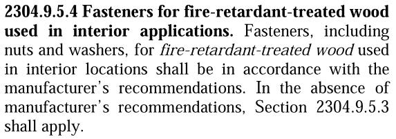
As shown in Figure 1 below, fasteners (including nuts and washers) used with FRTW in exterior conditions or where the wood’s service condition may include wet or damp locations need to be hot-dipped zinc-coated galvanized steel, stainless steel, silicon bronze or copper. This section does permit other fasteners (excluding nails, wood screws, timber rivets and lag screws) to be mechanically galvanized in accordance with ASTM B 695, Class 55 at a minimum. As shown in Figure 2, fasteners (including nuts and washers) used with FRTW in interior conditions need to be in accordance with the manufacturer’s recommendations, or, if no recommendations are present, to comply with 2304.9.5.3.
Figure 1: Section 2304.9.5.3 of the 2012 IBC (Source ICC)Figure 2: Section 2304.9.5.4 of the 2012 IBC (Source ICC)
In Type III construction where the exterior walls may be FRTW in accordance with 2012 IBC Section 602.3, one question that often comes up is whether the defined “exterior wall” should comply with Section 2304.9.5.3 or 2304.9.5.4. While there are many different views on this point, it is our opinion at Simpson Strong-Tie that Section 2304.9.5.4 would apply to the exterior walls. Since the exterior finishes of the building envelope are intended to protect the wood and components within its cavity from exterior elements such as rain or moisture, the inside of the wall would be dry.
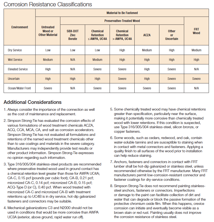
There are many FRTW product choices on the market; take a look at the American Wood Council’s list of treaters. Unlike the preservative-treated wood industry, however, the FRTW industry involves proprietary formulations and retentions. As a result, Simpson Strong-Tie has not evaluated the FRTW products. In our current connector and fastener catalogs, C-C-2026 Wood Connector Construction and C-F-25 Fastening Systems, you will find a newly revised Corrosion Resistance Classifications chart, shown in Figure 3 below, which can be found on page 15 in each catalog. The FRTW classification has been added to the chart in the last column. The corrosion protection recommendations for FRTW in various environmental applications is set to medium or high, corresponding to a number of options for connectors and fasteners as shown in the Corrosion Resistance Recommendations chart, shown in Figure 4. These general guideline recommendations are set to these levels for two reasons: (1) there are unknown variations of chemicals commercially available on the market, and (2) Simpson Strong-Tie has not conducted testing of these treated wood components.
The information above is not the only information readily available. There are many different tests that can be done on FRTW, as noted in the Western Wood Preservers Institute’s document. One such test for corrosion is Military Specification MIL-1914E, which deals with lumber and plywood. Another is AWPA E12-08, Standard Method of Determining Corrosion of Metals in Contact with Treated Wood. Manufacturers of FRTW products who applied for and received an ICC-ES Evaluation Report must submit the results of testing for their specific chemicals in contact with various types of steel. ICC-ES Acceptance Criteria 66 (AC66), the Acceptance Criteria for Fire-Retardant-Treated Wood, requires applicants to submit information regarding the FRTW product in contact with metal. The result is a section published in each manufacturer’s evaluation report (typically Section 3.4) addressing the product use in contact with metal. Many published reports contain similar language, such as “The corrosion rate of aluminum, carbon steel, galvanized steel, copper or red brass in contact with wood is not increased by (name of manufacturer) fire-retardant treatment when the product is used as recommended by the manufacturer.” Structural engineers should check the architect’s specification on this type of material. Product evaluation reports should also be checked to ensure proper specification of hardware and fastener coatings to protect against corrosion. Each evaluation report also contains the applicable strength adjustment factors, which vary from one product to another.
Selecting the proper FRTW product for use in your building is crucial. There are many different options available. Be sure to select a product based on the published information and to communicate that information to the entire design team. Evaluation reports are a great source of information because the independently witnessed testing of manufacturers has been reviewed by the agency reviewing the report. Finally, understanding FRTW chemicals and their behavior when in contact with other building products will ensure expected performance of your structures.
What has been your experience with FRTW? What minimum recommendations do you provide in your construction documents?
Structures and connections can be designed either using Allowable Strength Design (ASD) method or Load and Resistance Factor Design (LRFD) method. In the ASD method, the allowable strength is calculated by dividing the nominal strength by a safety factor. In the LRFD method, the design strength is calculated by multiplying the nominal strength by the resistance factor. In design, the adjusted ASD design value is compared to a calculated load or stress. As long as the adjusted ASD design value exceeds the calculated load of stress, then the ASD design value is judged safe. In LRFD design, the nominal strength is equated to factored loads. If the factored strength is greater than the factored loads, then the design can be accepted. ASD is the more common method adopted in the professional world.Continue Reading
Engineered wood products have been used in wood-framed construction for many decades. Early forms of engineered wood include plywood as replacement for 1x wood sheathing and glu-laminated beams that could be fabricated in larger sizes with optimized material utilization. I-joists utilizing deep plywood webs and solid sawn lumber flanges solved the challenge of longer floor spans. Oriented strand board (OSB) eventually replaced plywood in the webs, while the innovation of laminated veneer lumber (LVL) became common in the flange material.
In addition to I-joists, structural composite lumber is widely used as a replacement for solid lumber. This could be for a number of reasons such as availability of longer lengths, straighter sections and higher strengths. Structural composite lumber (SCL) may be LVL, parallel strand lumber (PSL), laminated strand lumber (LSL) or oriented strand board (OSB).
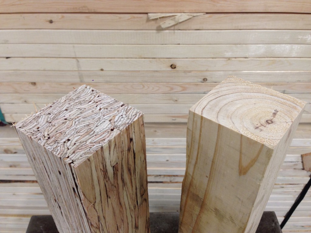
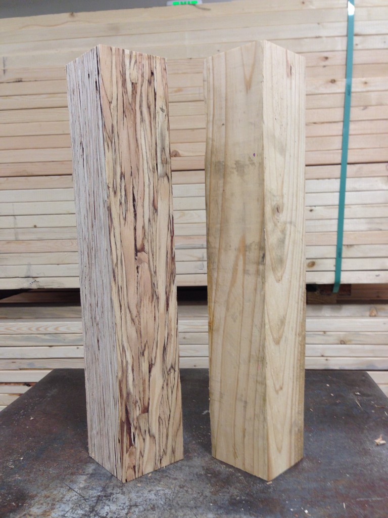
Douglas fir and PSL PostDouglas fir and PSL Post
Structural composite lumber has two faces. If the cross-section is rectangular, say 3½x5¼, the narrow face will show the edges of the SCL layers. In a square section, the face that shows the SCL layers is still referred to as the narrow face. Fasteners will have lower performance when they are installed in the narrow face of SCL. While this is not an issue for beams, Simpson Strong-Tie connectors such as post bases, column caps or holdowns may have reduced allowable loads when installed on the narrow face of SCL columns.
Test setup and failure mode of HDUE installed on LVLTest setup and failure mode of HDUE installed on LVLCC Column Cap Setup on LVL
To support the use of Simpson Strong-Tie connectors installed on SCL post material, we have run many tests over the years. The reductions are published in the technical bulletins, T-C-SCLCLM25 (U.S. version) and T-C-SCLCLMCAN25. The reduction factors range from 0.45 to 1.0, and vary based on SCL material type – LSL, PSL, or LVL – and also by connector and fastener type.
It is important to understand the magnitude of the reductions. While narrow face installations may be unavoidable, engineers will need to specify the correct lumber and hardware combination to meet the design loads.
A few days ago, I was speaking to a customer about an application using nail substitutions for a joist hanger installation. Her questions come up often, so I thought I would dedicate a blog post to some of the resources available that cover the use of different nails in connectors.
Designers and builders often wish to use different fasteners than the catalog specifies. The application could require short nails that don’t penetrate through the back of a ledger or they want to use screws or sinker nails for easier installation. The Wood Connectors Catalog provides multiple options for alternate nailing for face mount hangers and straight straps on page 24.
The load adjustments for alternate fasteners cover substitutions from a common diameter of 16d to a 10d, or a 10d to an 8d. Multiple different replacement lengths are also covered, with reduction factors ranging from 0.64 to 1.0.
It is important to remember that double shear hangers require 3” minimum joist nails. Short nails installed at an angle in double shear hangers will not have adequate penetration into the header.
Pneumatic nail guns used for connector installation are commonly referred to as positive placement nail guns. These tools either have a nose piece that locates connector hole, or the nail itself protrudes from the tool so that the installer can line the nail up with the hole. Most positive placement tools do not accept nails longer than 2½”, so framers using these tools will want to use 1½” or 2½” nails. To accommodate installers using pneumatic nails, we have a technical bulletin T-PNUEMATIC. This bulletin provides adjustment factors for many of our most common embedded holdowns, post caps and bases, hangers and twist straps.
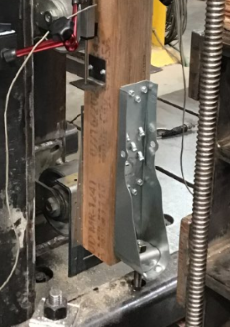
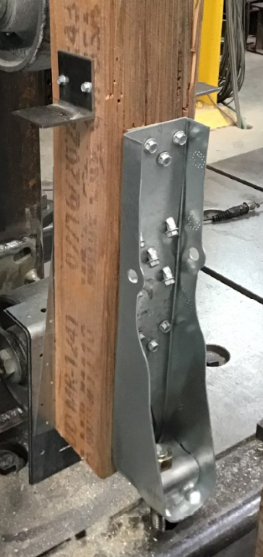
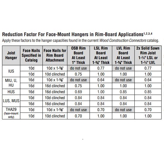
The question of nail size also comes up when attaching hangers to rim board, which can range from 1” to 1¾”. The adjustment factors in C-2013 don’t necessarily apply with rim board, since the material may be thinner the length of the nails used. We also have a technical bulletin for that application – T-RIMBDHGR.
Rim Board Reduction Factors
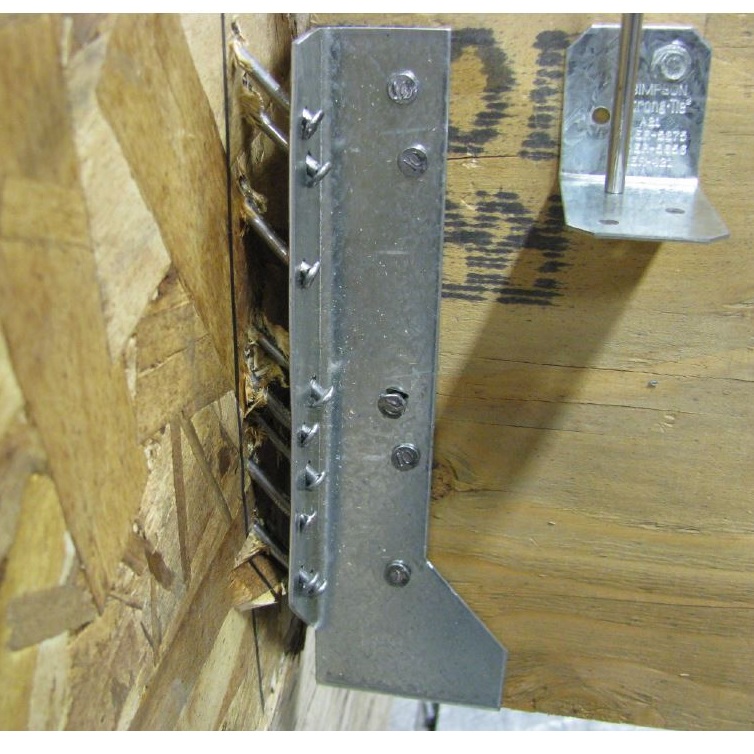
Several of the reduction factors are the same as those in the catalog. Testing of hangers with 10dx1½ nails on 1” OSB or 1¼” LVL did not do as well, however. We observed that once the nails withdrew a little bit under load, they quickly lost capacity. For that reason, we recommend full length 10d or 16d nails on those materials.
Rim board failure
Understanding that alternate fasteners are available for many connectors can help you pick the right fastener for you application. When you specify a connector, it is important to also specify the fasteners you require to achieve your design load.
This is Part 2 of a four-part series I’ll be doing on how connectors, fasteners, anchors and cold-formed steel systems are load rated. ReadPart 1 and Part 1A. These loads just can’t be right! Occasionally, I get this statement from engineers. This happens when they have been specifying commodity fasteners based on NDS load values and they get their first look at our higher screw values. Then the call comes in. They want to talk to someone to confirm what they are seeing is correct. I assure them the loads are right and give them this brief overview of how we got here:
Our first structural screw, the Simpson Strong-Tie(R) Strong-Drive(R) SDS, was originally load rated by plugging the bending yield strength and diameter into the NDS yield limit equations and using the load value from the governing failure mode. As later editions of the NDS modified the calculations and we did more testing, we found that the tested ultimate load of the SDS screw could be as much as ten times greater than the allowable load generated from the NDS equations. Continue Reading
We use cookies on this site to enhance your user experience. By clicking "I AGREE" below, you are giving your consent for us to set cookies. Privacy PolicyI AGREE
Privacy & Cookies Policy
Privacy Overview
This website uses cookies to improve your experience while you navigate through the website. Out of these cookies, the cookies that are categorized as necessary are stored on your browser as they are essential for the working of basic functionalities of the website. We also use third-party cookies that help us analyze and understand how you use this website. These cookies will be stored in your browser only with your consent. You also have the option to opt-out of these cookies. But opting out of some of these cookies may have an effect on your browsing experience.
Necessary cookies are absolutely essential for the website to function properly. This category only includes cookies that ensures basic functionalities and security features of the website. These cookies do not store any personal information.
Any cookies that may not be particularly necessary for the website to function and is used specifically to collect user personal data via analytics, ads, other embedded contents are termed as non-necessary cookies. It is mandatory to procure user consent prior to running these cookies on your website.