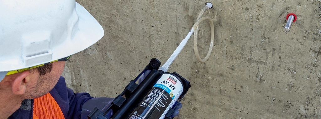
In general, post–installed adhesive anchor design per ACI 318 Chapter 17 is relatively straightforward. In practice, however, post–installed anchorage can often become challenging because of fast–track project schedules, supply issues, ever-changing weather conditions, design conflicts/changes, or unexpected field conditions.
Tag: ICC-ES
Construction Referees: Evaluation Processes for Alternative Building Products
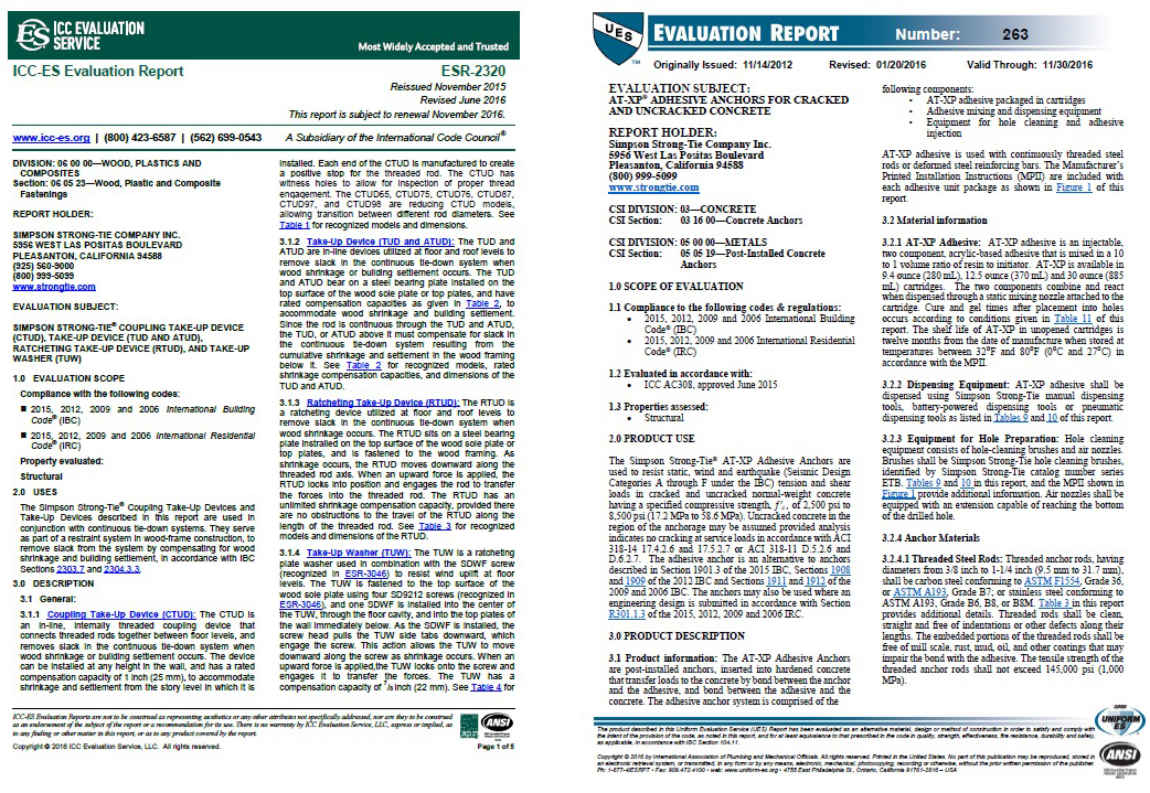
In a perfect world, every single product used in building would undergo a rigorous, independent evaluation process to determine its compliance with established safety codes and standards prior to its appearance in the market. “Alternative” building products and design methods are very much a reality of the construction industry, however. All the same, when Designers and building officials must decide whether to specify or approve such products, there are still review organizations and processes that help them evaluate whether or not the products meet the required safety standards to protect the public. In this post, Jeff Ellis, Simpson Strong-Tie Director of Codes and Compliance, delineates the process involved when an evaluation service entity, such as ICC-ES, issues an evaluation report (ER) for an alternative building product or method.
Continue Reading
Q&A About MPBZ Moment Post Base
This week’s post was written by Jhalak Vasavada, Research & Development Engineer at Simpson Strong-Tie.
Continue Reading
AC398 Now Includes Moment Evaluation of Cast-in-Place Post Bases
This week’s post was written by Jhalak Vasavada, Research & Development Engineer at Simpson Strong-Tie.
When we launched our new, patent-pending MPBZ moment post base earlier this year, the evaluation of the moment capacity of post bases was not covered by AC398 – or by any other code, for that matter. There wasn’t a need – there were no code-accepted connectors available on the market for resisting moment loads.
Continue Reading
New Moment-Resisting Post Base
Jhalak Vasavada is currently a Research & Development Engineer for Simpson Strong-Tie. She has a bachelor’s degree in civil engineering from Maharaja Sayajirao (M.S.) University of Baroda, Gujarat, India, and a master’s degree in structural engineering from Illinois Institute of Technology, Chicago, IL. After graduation, she worked for an environmental consulting firm called TriHydro Corporation and as a structural engineer with Sargent & Lundy, LLC, based in Chicago, IL. She worked on the design of power plant structures such as chimney foundations, boiler building and turbine building steel design and design of flue gas ductwork. She is a registered Professional Engineer in the State of Michigan.
At Simpson Strong-Tie, we strive to make an engineer’s life easier by developing products that help with design efficiency. Our products are designed and tested to the highest standards, and that gives structural engineers the confidence that they’re using the best product for their application.
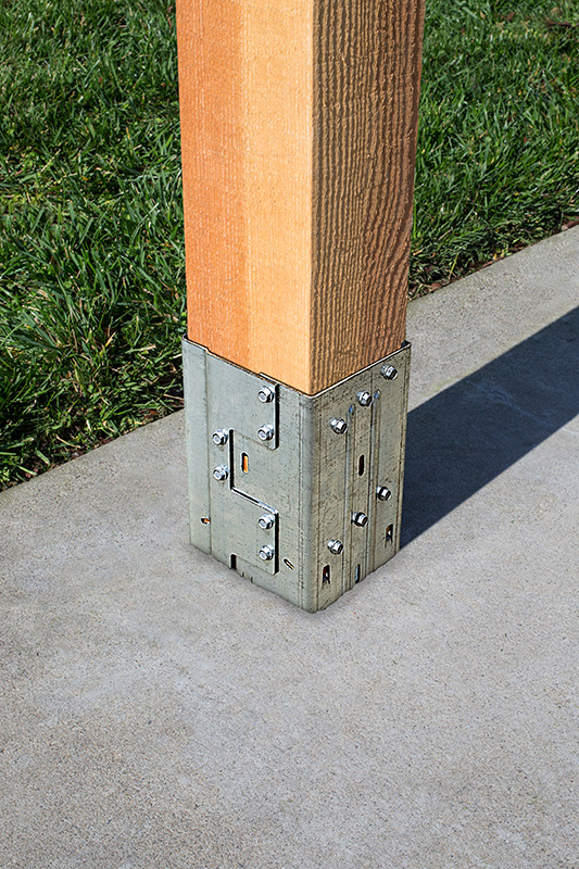
Having worked in the design industry for almost a decade, I can attest that having a catalog where you can select a product that solves an engineer’s design dilemma can be a huge time- and money-saving tool. Design engineers are always trying to create efficient designs, although cost and schedule are always constraints. Moment connections can be very efficient — provided they are designed and detailed correctly. With that in mind, we developed a moment post base connector that can resist moment in addition to download, uplift and lateral loads. In this post, I would like to talk about moment-resisting/fixed connections for post bases and also talk about the product design process.
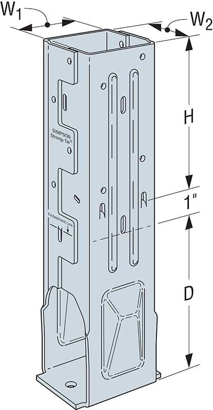
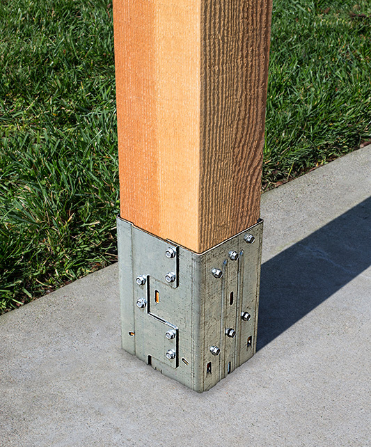
Lateral forces from wind and seismic loads on a structure are typically resisted by a lateral-force-resisting system. There are three main systems used for ordinary rectangular structures: (a) braced frames, (b) moment frames and (c) shearwalls. Moment frames resist lateral forces through bending in the frame members. Moment frames allow for open frames by eliminating the need for vertical bracing or knee bracing. Moment resistance or fixity at the column base is achieved by providing translational and rotational resistance. The new patent-pending Simpson Strong-Tie® MPBZ moment post base is specifically designed to provide moment resistance for columns and posts. An innovative overlapping sleeve design encapsulates the post, helping to resist rotation at its base.
The allowable loads we publish have what I call “triple backup.” This backup consists of Finite Element Analysis (FEA), code-compliant calculations and test data. Here are descriptions of what I mean by that.
Finite Element Analysis Confirmation
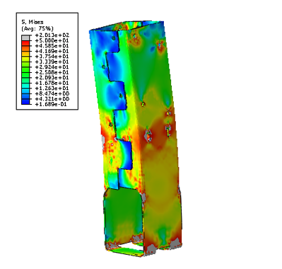
Once a preliminary design for the product is developed, FEA is performed to confirm that the product behaves as we expect it to in different load conditions. Several iterations are run to come up with the most efficient design.
Code-Compliance Calculations
Load calculations are prepared in accordance with the latest industry standards. The connector limit states are calculated for the wood-post-to-MPBZ connection and for MPBZ anchorage in concrete. Steel tensile strength is determined in accordance with ICC-ES AC398 and AISI S100-07. Wood connection strength is determined in accordance with ICC-ES AC398 and AC13. Fastener design is analyzed as per NDS. SDS screw values are analyzed using known allowable values per code report ESR-2236. The available moment capacity of the post base fastened to the wood member is calculated in accordance with the applicable bearing capacity of the post and lateral design strength of the fasteners per the NDS or ESR values. Concrete anchorage pull-out strength is determined in accordance with AC398.
Test Data Verification
The moment post base is tested for anchorage in both cracked and uncracked concrete in accordance with ICC-ES AC398.
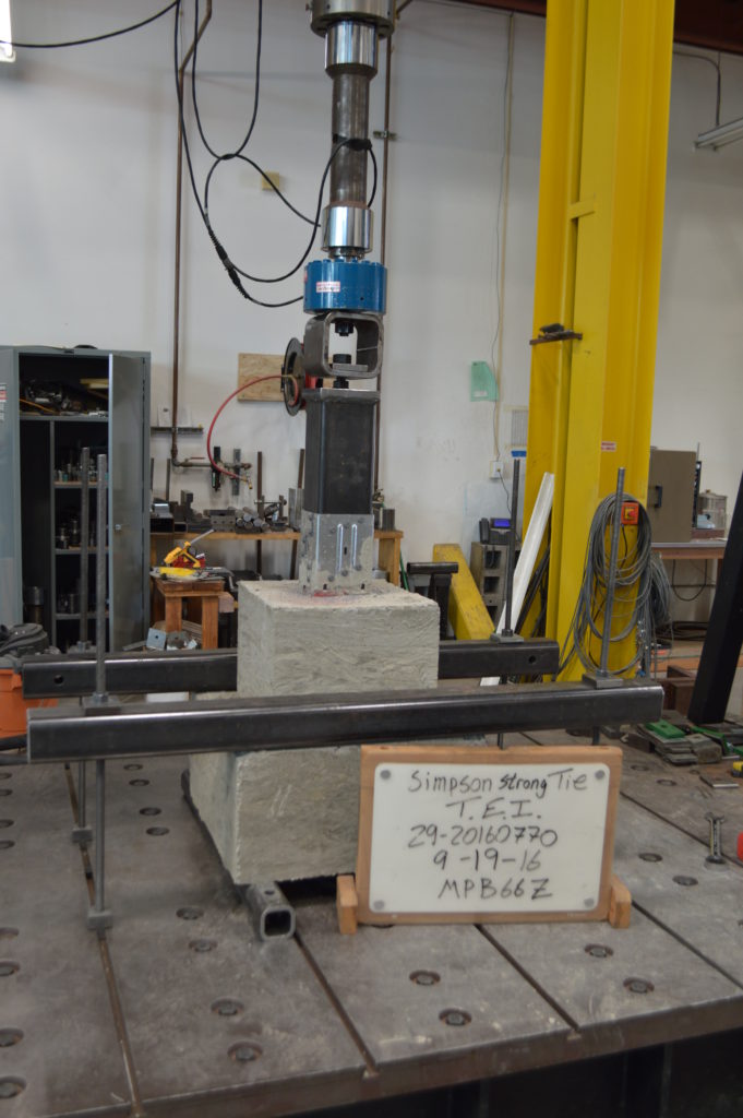
The moment post base assembly is tested for connection strength in accordance with ICC-ES AC13.
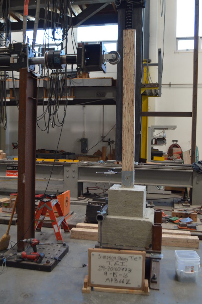
The assembly (post and MPBZ) is tested for various loading conditions: download, uplift and lateral load in both orthographic directions and moment. Applicable factor(s) of safety are applied, and the controlling load for each load condition is published in the Simpson Strong-Tie Wood Construction Connectors Catalog.
Now let’s take a look at a sign post base design example to see how the MPBZ data can be used.
Design Example:
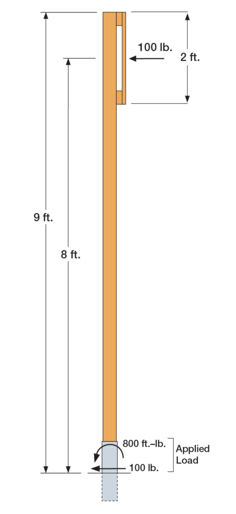
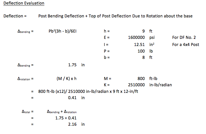
The MPB44Z is used to support a 9ʹ-tall 4×4 post with a 2ʹ x 2ʹ sign mounted at the top. The wind load acting on the surface of the sign is determined to be 100 lb. The MPB44Z is installed into concrete that is assumed to be cracked.
- The design lateral load due to wind at the MPB44Z is 100 lb.
- The design moment due to wind at the MPB44Z is (100 lb.) x (8 ft.) = 800 ft.-lb.
- The Allowable Loads for the MPB44Z are:
- Lateral (F1) = 1,280 lb.
- Moment (M) = 985 ft.-lb.
- Simultaneous Load Check:
- 800/985 + 100/1,280 = 0.89. This is less than 1.0 and is therefore acceptable.
We are very excited about our new MPBZ! We hope that this product will get you excited about your next open-structure design. Let us know your thoughts by providing comments here.
Construction Referees: Evaluation Processes for Alternative Building Products
 There are products used in every building not referenced by the codes or standards.
These products can impact safety, public health and general welfare through their effect on structural strength, stability, fire resistance and other building performance attributes. I-code Section 104.11 (Alternative materials, design, and methods of construction and equipment) provides guidance on how these products are approved for use in the built environment and identifies the Building Official as the decision-maker. This is similar to a referee determining a player’s compliance with the rules.
Building Officials see submittals for a wide variety of alternative building products ranging from the simple to the very complex. The amount of data included in these submittals and their relevance and completeness varies significantly from insufficient and minimal to complete and very thorough. In the absence of publicly developed and majority-approved provisions, the Building Official is tasked to ensure the data provided is appropriate and adequately proves the alternative product meets code intent to protect public safety, no matter the product type or complexity. This is compared to the robust code and standards process in which committees with balanced representation publicly develop and deliberate on provisions in order to protect public safety. The question arises whether the 104.11 requirement implies that a similar robust process be used in the development of test and evaluation requirements for alternative products as is used for the development of code and standard provisions where there is public debate, resolution of negative opinions and a majority approval of the requirements. Requiring a similar code development process for alternative products would seems to make sense. Otherwise, a less rigorous process might be employed by those seeking to avoid a more robust code and standard process so as to achieve quicker and less stringent approval for their alternative products.
 Some may argue that having to use a “code-like” evaluation process for alternative products would add too much of a burden in time and cost, and that it’s not necessary since individual registered design professionals and building officials have enough time, resources and expertise to determine acceptability. But this begs the question of why a similar public majority-approval process should not be required for new products as it is required for code-referenced products. Another question that comes up is ongoing acceptance of an alternative product, as their manufacture may have changed since their approval. Additionally, different jurisdictions have different expertise and resources and this can lead to different standards for approval for alternative products, leading to inconsistency.
Is there a solution which balances providing innovative and cost-effective alternative building product solutions to the industry in a timely manner with providing a thorough product assessment using a process similar to the codes and standards to better ensure consistency and public safety? Accredited building product certification companies, or evaluation service companies, that use a publicly developed and majority-approved acceptance or evaluation criteria and publish an evaluation report with the product’s description, design and installation requirements and limitations provide such a solution. These evaluation service companies are a third-party resource for building officials to assist in their determination of whether an alternative product meets code intent and should be approved for use in their jurisdiction.
The number of evaluation service companies has been increasing. The ICC Evaluation Service and the IAPMO Uniform Evaluation Service, two of the better-known such companies, are both ANSI accredited to ISO/IEC 17065 (Conformity Assessment – Requirements for bodies certifying products, processes, and services) to provide building-code product certifications (ICC-ES, IAPMO UES). However, accreditation by itself mainly verifies a certain process is implemented to ensure consistency and confidentiality. Both companies also have a public acceptance or evaluation criteria process. This process includes an evaluation committee made up of building enforcement officials. These officials evaluate the proposed criteria, listen to expert and industry input and only approve the criteria by a majority vote if products evaluated to those criteria will meet code intent. This is similar to how the codes and standards are developed — a transparent public process and a majority approval of requirements and not just an opinion of one or a couple of individuals.
The alternative building product review process for ICC-ES and IAPMO UES is similar and has the following important components.
- CRITERIA: The accredited product evaluation service develops an acceptance or evaluation criteria, with the manufacturer’s and public’s input, that is publicly debated, revised and ultimately approved by a majority vote of a committee of building enforcement officials.
- TESTING: The manufacturer contracts out to an accredited independent third-party test laboratory to either perform or witness the product testing in accordance with the criteria.
- REVIEW: Registered design professionals with the accredited product evaluation service evaluate the testing and analyses performed and sealed by registered design professionals with the manufacturers or their representatives. The product evaluation service then publishes the evaluation report to their website, and the report typically contains the product description, design and installation requirements and
 limitations.
 - CONTINUOUS COMPLIANCE: The manufacturer’s quality system is inspected at least annually by the product evaluation service or an accredited third-party
inspection agency to ensure that the product currently being manufactured is the same as that which was evaluated.
While the term “product evaluation” is sometimes used, it is often “product certification” or “product conformity assessment.” ISO/IEC Guide 2:2004 defines “conformity assessment” as “Any activity concerned with determining directly or indirectly that relevant requirements are fulfilled. Some “product certification” companies also provide “product listing” services for when testing and evaluation requirements for the product are already in code-referenced consensus standards, making the development of acceptance criteria unnecessary, thus simplifying the process.
A couple of previous blog posts on evaluation or code reports that you may find informative discuss steps to obtain an evaluation or code report and provide a checklist to determine adequacy of a report.
A mechanism is available to the building industry to provide innovative and cost-effective alternative building products in a timely manner that implements a public and majority product acceptance criteria process, similar to the codes and standards development process. This solution involves the Building Official referencing building product evaluation service reports, based on acceptance criteria, offering a robust evaluation better ensuring that an alternative product meets code intent, thus protecting the public. In fact, several jurisdictions do require evaluation service reports for alternative products.
Should there be an easier path to approval for alternative products than for code-referenced products? What is a reasonable path to product approval? What basis do you use in reviewing evaluation or code reports to determine whether an alternative product is “in or out of -bounds”? We’d love to hear your thoughts.
Coating Evaluation for Fasteners – Code-Approved and Alternative Coatings
Who likes red rust? No one I know! How do we avoid corroding of fasteners? Corrosion can be controlled or eliminated by providing a corrosion-resistant base metal or a protective finish or coating that is capable of withstanding the exposure environment. When fasteners get corroded, they not only look bad from outside but can also lose their load capacity. To ensure continued fastener performance, we have to control for corrosion. This blog focuses on evaluating the corrosion resistance of the fasteners.
What does the building code specify?
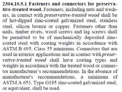
For use in preservative-treated wood, the IBC-2015 specifies fasteners that are hot-dipped galvanized, stainless steel, silicon bronze or copper. Section 2304.10.5.1 of IBC-2015 (Figure 1) covers fastener and connector requirements for preservative-treated wood (chemically treated wood). While chemically treated wood is part of the corrosion hazard, it is not the whole corrosion hazard. Weather exposure, airborne chemicals and other environmental conditions contribute to the corrosion hazard for metal hardware. In addition, the main issue with the code-referenced requirements for fasteners and connectors used with preservative-treated wood is that not all preservative treatments deliver the same corrosion hazard and not all fasteners can be hot-dip galvanized.
What if we want to use an alternative base material or coating for fasteners?
How do we evaluate the corrosion resistance of the alternative material or coating? The codes do not provide test methods to evaluate alternate materials and coatings. However, the International Code Council–Evaluation Service (ICC-ES) developed acceptance criteria to evaluate alternative coatings that are not code recognized for use in different environments. The purpose of acceptance criteria ICC-ES AC257, Acceptance Criteria for Corrosion-Resistant Fasteners and Evaluation of Corrosion Effects of Wood Treatment Chemicals, is twofold: (1) to establish requirements for evaluating the corrosion resistance of fasteners that are exposed to wood-treatment chemicals, weather and salt corrosion in coastal areas; and (2) to evaluate the corrosion effects of wood-treatment chemicals. In this blog post, we will concentrate on the evaluation of corrosion resistance of fasteners. The criteria provide a protocol to evaluate the corrosion resistance of fasteners where hot-dip galvanized fasteners serve as a performance benchmark. The fasteners evaluated by these criteria are nails or screws that are exposed directly to wood-treatment chemicals and that may be exposed to one or more corrosion accelerators like high humidity, elevated temperatures, high moisture or salt exposure.
The fasteners may be evaluated for any of the four exposure conditions:
- Exposure Condition 1 with high humidity. This test can be used to evaluate fasteners that could be exposed to high humidity. Typical applications that fall under this category are treated wood in dry-use applications.
- Exposure Condition 2 with untreated wood and salt water. This test can be used to evaluate fasteners that are above ground but exposed to coastal salt exposure.
- Exposure Condition 3 with chemically treated wood and moisture. This test covers all the general construction applications.
- Exposure Condition 4 with chemically treated wood and salt water. Typical applications include coastal construction applications.
Depending on the exposure condition being used for fastener evaluation, the fasteners are installed in wood that could be either chemically treated or untreated. Then the wood and the fasteners are placed in the chamber and artificially exposed to the evaluation environment. Two types of test procedures are to be completed for exposure condition 2 through 4. The purpose of these tests is not to predict the corrosion resistance of the coatings being evaluated, but to compare them to fasteners with the benchmark coating (ASTM A153, Class D) in side-by-side exposure to the accelerated corrosion environment.
ASTM B117 Continuous Salt-Spray Test
ASTM B117 is a continuous salt-spray test. For Exposure Condition 3, distilled water is used instead of salt water. The fasteners are continuously exposed to either moisture or salt spray in this test, and the test is run for about 1,440 hours after which the fasteners are evaluated for corrosion. This is an accelerated corrosion test that exposes the fasteners to a corrosive attack so the corrosion resistance of the coatings can be compared to a benchmark coating (hot-dip galvanized).
ASTM G85, Annex A5
The second test is ASTM G85, Annex A5 which is a cyclic test with alternate wet and dry cycles. The cycles are 1-hour dry-off and 1-hour fog alternatively. This is a cyclic accelerated corrosion test and relates more closely to real long-term exposure. This test is more representative of the actual environment than the continuous salt-spray test. As in the ASTM B117 test, the fasteners along with the wood are exposed to 1,440 hours, after which the corrosion on the fasteners is evaluated and compared to fasteners with the benchmark coating.
Test Method and Evaluation
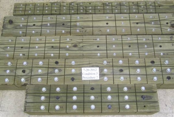
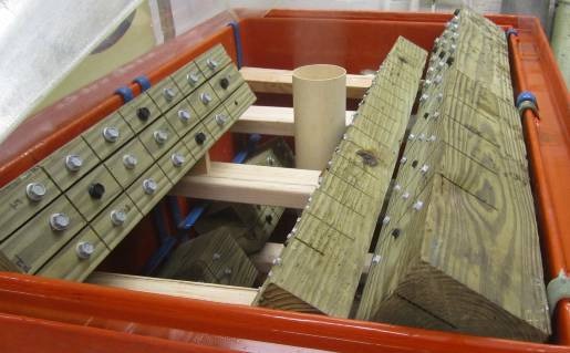
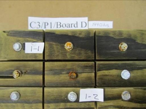
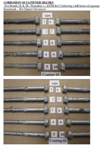
The test process involves installing 10 benchmark fasteners along with 10 fasteners for each alternative coating being evaluated. The fasteners are arranged in the wood with a spacing of 12 times the fastener diameter between the fasteners. A kerf cut is provided in the wood between the fasteners to isolate the fasteners as shown in Figure 2 and to ensure elevated moisture content in the wood surrounding the fastener shank. The moisture and retention levels of the wood are measured, and the fasteners are then installed in the chamber as shown in Figure 3 and exposed to the designated condition. The test is run for the period specified, after which the fasteners are removed, cleaned and compared to the benchmark for corrosion evaluation. Figure 4 shows the wood and fastener heads after 1,440 hours (60 days). The heads and shanks of the fasteners are visually graded for corrosion in accordance with ASTM D610. If the alternate coating performs equivalent to or better than the benchmark coating — that is, if the corrosion is no greater than in the benchmark — then the coating has passed the test and can be used as an alternative to the code-approved coating. Figure 5 shows the benchmark and alternative fasteners that are removed from the chamber after 1,440 hours.
As you can see, the alternative coatings have to go through extended and rigorous testing and evaluation as part of the approval process before being specified for any of the fasteners. Some alternative coatings provide even better corrosion resistance than the code recognized options. Sometimes, also, the thickness of these alternative coatings may be smaller than the thick coating required for hot-dip galvanized parts. Some of our coatings, such as the Double-Barrier coating, the Quik Guard® coating and the ASTM B695 Class 55 Mechanically Galvanized have gone through this rigorous testing and have been approved for use in preservative-treated wood in the AC257 Exposure Conditions 1 and 3. In addition, these coatings have been qualified for use with chemical retentions that are typical of AWPA Use Category 4A – General Ground Contact. No salt is found in AC257 Exposure Conditions 1 and 3. Please refer to our Fastener Systems Catalog, C-F-14, pages 13–15 for corrosion recommendations and pages 16–17 for additional information on coatings.
What do you look for specifically in a fastener? Do you have a preference for a certain coating type or color? Let us know in the comments below!
Florida Product Approvals Made Simple
This year, the new 5th Edition of the Florida Building Code was released and is now in effect statewide. First printed in 2002, the Florida Building Code was developed as part of Florida’s response to the destruction caused by Hurricane Andrew and other hurricanes in the state.
Another component, which I would like to take a closer look at in today’s post, is a separate Florida Product Approval system designed to be a single source for approval of construction products for manufacturers, Designers and code enforcers. This single system streamlines the previous approach of different procedures for product approval in different jurisdictions. While statewide approval is not required, many jurisdictions, manufacturers and specifiers prefer using the statewide system to the alternative, which is called local product approval. To ensure uniformity of the state system, Florida law compels local jurisdictions to accept state-approved products without requiring further testing and evaluation of other evidence, as long as the product is being used consistent with the conditions of its approval.
The rules of the Florida Product Approval system are in Florida Rule 61G20-3. Here is some basic information about Florida Product Approval.
The Florida Product Approval system is only available for “approval of products and systems, which comprise the building envelope and structural frame, for compliance with the structural requirements of the Florida Building Code.” So users will only find certain types of products approved there. However, if you work in areas where design for wind resistance is required, the Florida system can be a gold mine of information for tested, rated and evaluated products. Not only will you find products like Simpson Strong-Tie connectors with our ICC-ES and IAPMO UES evaluation reports, but thousands of other tested and rated windows, doors, shutters, roof covering materials and other products that don’t typically get evaluation reports from national entities. The specific categories of products covered under the Florida system are exterior doors, impact protective systems, panel walls, roofing, shutters, skylights, structural components and windows.
To protect consumers, a recent law passed in Florida states that a product may not be advertised, sold or marketed as offering protection from hurricanes, windstorms or wind-borne debris unless it has either State Product Approval or local product approval. Selling unapproved products in this way is considered a violation of the Florida Deceptive and Unfair Trade Practices Act.
Once a manufacturer understands the process for achieving a statewide approval, it is not difficult to achieve, but it can be expensive. The manufacturer must apply on the State of Florida Building Code Information System (BCIS) website at www.floridabuilding.org. To prove compliance with the code, the manufacturer must upload either a test report, a product certification from an approved certification entity, an evaluation report from a Florida Professional Engineer or Architect, or an evaluation report from an approved evaluation entity (ICC-ES, IAPMU UES, or Miami-Dade County Product Control). Then, the manufacturer must hire an independent validator to review the application to ensure it complies with the Product Approval Rule and that there are no clerical errors. Finally, once the validation is complete, staff from the Department of Business and Professional Regulation reviews the application. Depending on the method used to indicate code compliance, the application may be approved at that time or it may have to go through additional review by the Florida Building Commission.
Here are several ways to find out if a product is approved.
- For Simpson Strong-Tie products, we maintain a page on www.strongtie.com that lists our Florida Product Approvals.
- The Florida Department of Business and Professional Regulation maintains a page where users can search Product Approvals by categories such as manufacturer, category of product, product name, or other attributes such as impact resistance or design pressure.
- A third-party group we work with has created a website called www.ApprovalZoom.com that lists various product evaluations and product approvals. In addition to listing Florida Product Approvals, they also list ICC-ES evaluation reports, Miami-Dade County Notices of Acceptance, Texas Department of Insurance Approvals, Los Angeles Department of Building Safety Approvals, AAMA certifications and Keystone certifications among others.
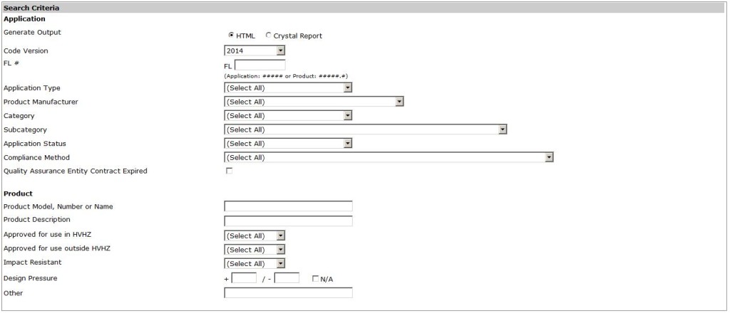
The process for searching for approved products on the Florida BCIS is fairly simple.
- Go to www.floridabuilding.org
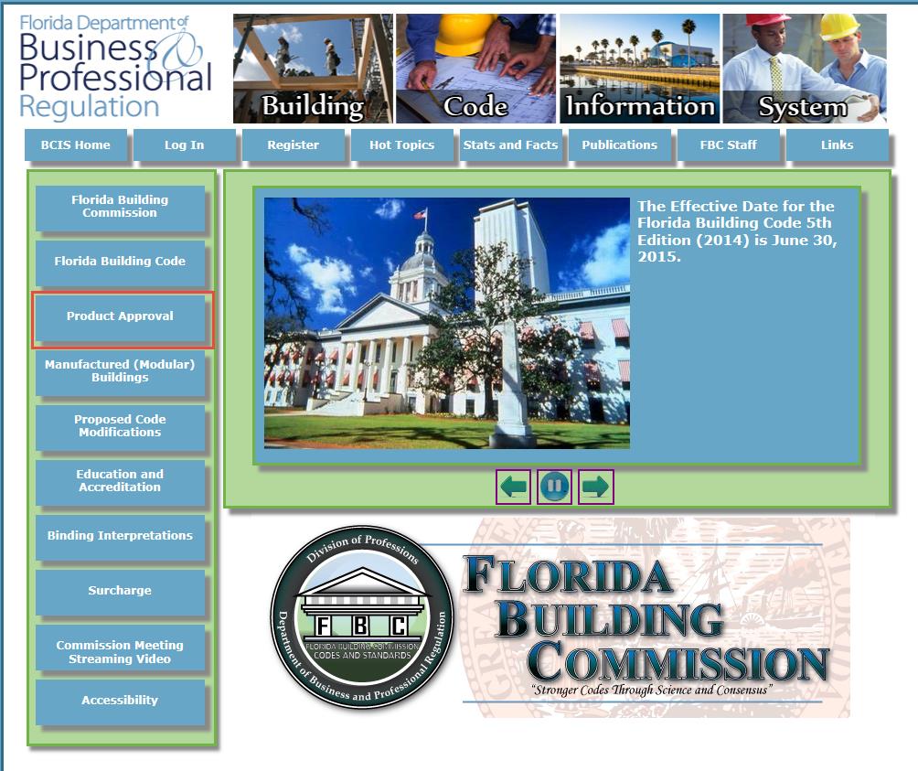
- On the menu on the left side of the page, click on Product Approval. Or, click this link to go directly to the search page.
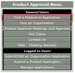
- On the Product Approval Menu, click on Find a Product or Application. Note that at this location you can also search for approved organizations such as certification agencies, evaluation entities, quality assurance entities, testing laboratories and validation entities.
- Ensure the proper Code Version is shown. The current 2014 Florida Code is based on the 2012 International Codes.
- At this point, several options can be searched. You can search for all approvals by a specific product manufacturer or a certain type of building component by searching Category and Subcategory, or if searching for a specific product, by entering the manufacturer’s name and the product name.
I hope you find the information contained in the Florida Product Approval system useful. Do you have other needs to find approved products?
Truss Repair Information: The Never-Ending Search
Truss repair is one of the most frequently asked about truss topics. Not surprisingly, when we asked for suggested truss topics in a truss blog earlier this year, truss repair information made the list. Because the summer months bring about a peak in new construction – and plenty of truss repairs to go along with it – the beginning of June is the perfect time to visit this topic.
From trusses that get dropped or cut/drilled/notched at the jobsite, to homeowners who want to modify their existing trusses to add a skylight or create attic space to fire-damaged trusses, a multitude of scenarios fall under the broad topic of truss repair. Today’s post focuses on various references and resources that can provide some assistance. But first it helps to break down the broad “truss repair” topic into more manageable-sized categories.
New Construction vs. Recent Construction vs. Old Construction
By far, the easiest type of truss repair is new construction, when the trusses either haven’t been installed yet or are still in the process of being installed. Whether the repair is relatively simple (e.g. a broken web) or a little more complicated (e.g. the trusses need to be stubbed), the beauty of new truss construction is that the truss manufacturer – and truss Designer – can be contacted and help with the repair. The truss Designer can easily open up the truss designs in the truss design software, quickly evaluate the trusses for the appropriate field conditions and issue a repair.
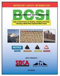
A good reference related to truss repairs for new truss construction is the Building Component Safety Information (BCSI) booklet jointly produced by SBCA and TPI. Section B5 of the BCSI booklet, which is also available as a stand-alone summary sheet, covers Truss Damage, Jobsite Modifications & Installation Errors. This field-guide document describes the steps to take when a truss at the jobsite is damaged, altered or improperly installed, common repair techniques, and the information to provide to the truss manufacturer when a truss is damaged, which will assist in the repair process.
The next easiest truss type to repair is recent construction, where the trusses were constructed recently enough that: a) the truss plates are easy to identify, and b) the truss design drawings may even still be available. In these cases, design professionals other than the original truss Designer may be contacted to repair the trusses. For some types of repairs, the design professional can work off the truss design drawing to design the repair. Other times it might be necessary to model and analyze the truss using structural design software; alternatively, a truss manufacturer can be contacted to model the truss in their truss design software for a fee.
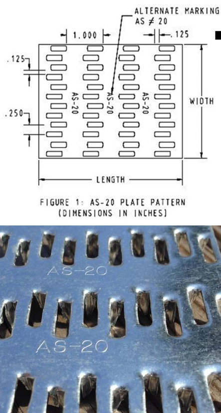
Often, the design professional wants to know the design values for the truss plates that were used to construct the truss. If there are truss design drawings available, they will indicate which truss plates were used in the design, and then the truss plate manufacturer can be contacted for more information. It is also easy to search for the truss plate code reports online (for instance, check icc-es.org). If no truss design drawing is available, there is still a way to identify the truss plates. Currently, there are only five major truss plate manufacturers in the United States, and they are listed on the Truss Plate Institute website. That makes identification of the truss plates used in recently constructed trusses easier because all of the current manufacturers’ plates will have markings that are described in their code reports. (Note that there are also a couple of truss manufacturers in the U.S. that manufacture their own truss plates.)
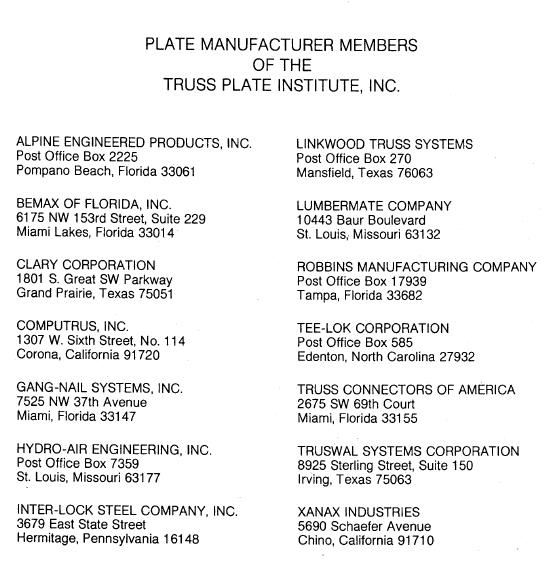
Finally, the most challenging type of trusses for truss repairs are those found in older buildings. Design professionals involved in these types of repair often aren’t sure where to start. Truss design drawings are often not available, and the act of trying to identify the truss plate manufacturer is challenging at best, unsuccessful at worst. As a point of reference, there were 14 truss plate manufacturers that were TPI members in 1987 (see image below), and only one of those companies is still in the current list of five companies. Therefore, the truss plates found in a truss built around 1987 will be difficult to identify. One option is to contact TPI and see if they can point you in the right direction.
Simple vs. Complex Repairs
Another way to break down truss repairs is to divide them into easy and challenging repairs. People often ask for “standard” truss repair details. Unfortunately, standard details only address the simplest types of repair; and those usually aren’t the types of repair that are asked about. Details simply cannot cover the wide range of truss configurations and every type of repair situation.
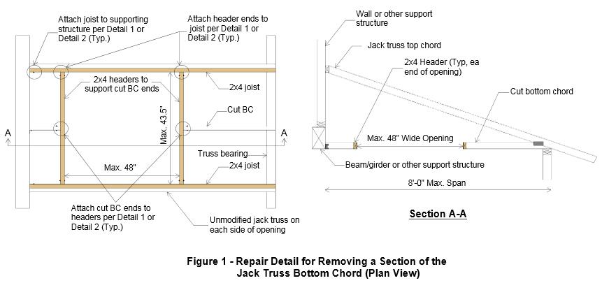
With the exception of simple repairs, most truss repairs rely heavily on the judgment and experience of the design professional doing the repair. And because there are not entire textbooks devoted to truss repair (that I am aware of, anyway), Designers must pull from a variety of resources, both to learn more about truss repair and to design the repair. For repairs using plywood or OSB gussets, the APA Panel Design Specification is a must-have reference. Some people prefer to use dimension lumber scabs for their repairs, whenever possible, simply because they are more familiar with dimension lumber (and the NDS) than they are with Plywood/OSB or the APA Panel Design Specification.
Next, the fasteners for the repair must be selected and the allowable loads determined. For nail design values, I am a big fan of the American Wood Council’s Connection Calculator, which provides allowable nail shear values for just about any combination of main and side members that you can think of, including OSB and plywood side members – particularly handy for truss repairs. For more complex repairs, and especially repairs involving higher forces, an excellent fastener choice is a structural wood screw such as our Strong-Drive® SDS or SDW screws. When I worked in the R&D department at Simpson Strong-Tie, a frequently asked question was whether we had double-shear values for our SDS screws. The questions always seemed to come from Designers who wanted them for truss repairs. Fortunately, we do have double-shear values for our SDS screws.. You can find them on page 319 of our Fastening catalog.

The Strong-Drive SDW screw was developed after the SDS screw, and while there are currently no double-shear values for the SDW, it is still another good option for repairs.
Fire-Damaged Trusses and Truss Collapses
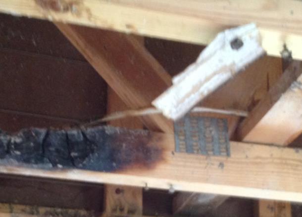
These situations are in a category by themselves because they go beyond even the most complex repairs involving a major modification to the truss. The biggest difference is that the latter case involves mostly known facts and perhaps some conservative assumptions, whereas damage due to fire or collapse includes many unknowns. Most of the truss Designers I have spoken to about truss damage due to fire or truss collapse often recommend replacement of the trusses rather than repair because it is usually too difficult to quantify the damage to the lumber and/or joints. In fires, there can be “hidden” damage due to the sustained high temperatures, while the truss appears to have no visible damage. Likewise, in a truss collapse, not only may there be too many breaks in the trusses involved in the collapse, but there may also be trusses that suffered severe stresses during the collapse and have damage that is not visible. To attempt a repair in either of these cases often requires an inspection at the jobsite, and the result may still end up being replacement of some or all of the trusses. Therefore, the cost of a full-blown inspection should be weighed against the cost of replacing the trusses.
The Structural Building Components Association website has a page with information pertaining to fire issues. It includes a couple of documents related to fire damage that are worth checking out.
Beyond the Blog: Where to Get More Truss Repair Information
The best bet for getting practical design information related to truss repairs is to keep an eye out for short courses, workshops or seminars. ASCE has hosted a Truss Repair Seminar (Evaluating Damage and Repairing Metal Plate Connected Wood Trusses) in the past and may very well offer something like it again. Virginia Tech recently hosted a short course on Advanced Design Topics in Wood Construction Engineering, which included a section on Wood Truss Repair Design Techniques.
What other references or resources for truss repair do you use? Are there any upcoming truss repair courses that you know of? Please let us know in the comments below!
Code Reports: Uniform Application of Code Intent in a Diverse Environment
Woodworks invited me to do a presentation on Testing and Evaluation of Products for Wood-framed Construction, and I found you can’t really talk about testing without talking about the test standards and criteria used in product evaluations. Usually the goal in testing to these standards is to show compliance with the intent of the building code and have the product listed in a code report.
Why not just follow the code?
Innovative architectural and structural building products not addressed by the building code are in every building. Revisions to the building code are considered on a three-year cycle and some standards are on a five-year cycle. Sometimes it may take several cycles to address a new building product.


